© 2017, IRJET | Impact Factor value: 5.181 | ISO 9001:2008 Certified Journal | Page 2379
ANALYSIS AND GAIN ENHANCEMENT OF DIFFERENT SHAPES OF SHAPES
OF MICROSTRIP PATCH ANTENNA
Dr.S.Sathiya Priya, M.E,Ph.D
1, A.Supriya
2, B.Meena Shivani
31Professor, ECE Department, Panimalar Institute of Technology, Tamil Nadu, India. 2Final Year UG Student, ECE Department, Panimalar Institute of Technology, Tamil Nadu, India. 3Final Year UG Student, ECE Department, Panimalar Institute of Technology, Tamil Nadu, India. -- -- -- -- -- -- -- -- -- -- -- -- -- -- -- -- -- -- -- -- -- -- -- --***- -- -- -- -- -- -- -- -- -- -- -- -- -- -- -- -- -- -- --- -- -- -- -- -- ABSTRACT - Microstrip patch antenna with microstrip
feeding gives the better gain. In this paper, the gain obtained for eight different shapes(square patch, circular patch, circular loop, square loop, cross dipole, square aperture, jeruslem cross, gridded square frequency selective surface) of microstrip patch antenna is analyzed carefully with microstrip feeding. Then designing is done using Advanced Design System(ADS) software by including Electromagnetic Band Gap(EBG) to microstrip feeding. The result was that the obtained gain is higher for microstrip patch antenna with microstrip feeding and EBG when compared to using microstrip feeding alone.
Keywords: Microstrip patch antenna, Electromagnetic band gap, Gain, return loss, ADS software, resonant frequency.
INTRODUCTION:
MICROSTRIP ANTENNA: A Microstrip or Patch antenna consists of a radiating patch on one side of a dielectric substrate. That dialectic substrate has a ground plane on the other side [3-4].
In basic principles of operation in Microstip or Patch antenna, that patch performs approximately as a resonant cavity (short circuit walls on top and bottom, open-circuit walls on the sides).In a cavity, only certain modes are allowed to occur at different resonant frequencies. If the antenna is excited at a resonant frequency, a strong field is set up inside the cavity and a strong current on the(bottom) surface of the patch. This produces significant radiation (a good antenna).
A Microstrip or Patch antenna is a low-profile antenna that has various advantages over other antennas –it is a light weight, inexpensive and easy to integrate with accompanying electronics [9]. Since Microstrip antenna are often integrated with other Microstrip circuitry, a compromise must be reached between good antenna performance and circuit design. The radiating element are photo etched along with the feed lines on the dielectric substrate. The radiating patch may be square, rectangle, dipole, circular, elliptical, triangle or any other configuration [4]. While the antenna can be 3D in structure (eg. wrapped around a cylinder), it is flat and that is why patch antennas are sometimes referred to as Planar antennas.
© 2017, IRJET | Impact Factor value: 5.181 | ISO 9001:2008 Certified Journal | Page 2380 The various shapes of Microstrip antennas are
rectangular, circular, triangular, dipole and elliptical with rectangular and circular shapes the most commonly used[10]. The different shapes are following below in the fig 2.
Fig2: Different shapes of microstrip patch antenna FEEDING METHODS:
A feed line is used to excite to radiate by direct contact. There are many different methods of feeding and four most popular methods:
Microstrip line feed Aperture coupling Proximity coupling Coaxial probe.
GAIN ENHANCEMENT TECHNIQUES:
By using this Gain Enhancement Technique of EBG, the gain of the microstrip antenna have been increased. Without EBG the gain of the microstrip antenna will be very low while compared with EBG antenna gain. Among these applied EBG microstrip antenna, square aperture microstrip antenna has the highest antenna gain.
DESIGN ANALYSIS:
A. Design calculation for rectangular microstrip antenna:
Calculation for width of the patch(W): W=
√ √
Effective dielectric constant calculation ( :
+ (1+12
Effective length calculation ( :
=
√
Length extension calculation ( :
=0.412h
Actual length of patch calculation(L): L= -2
Ground plane dimension calculation (
= 6h+L
© 2017, IRJET | Impact Factor value: 5.181 | ISO 9001:2008 Certified Journal | Page 2381 Where,
=Effective dielectric constant =Dielectric constant of substrate h=Height of dielectric substrate W=Width of the patch.
B. Design specification
The three importance parameters for the design of a different shapes of Microstrip Patch Antenna [8] are:
Frequency of Operation
The resonant frequency of the antenna must be selected appropriately. The resonant frequency selected for my design is 2.4GHz.
Dielectric constant of the substrate ( ) The dielectric material used for my design is FR4. It has a dielectric constant of 4.4. Height of dielectric substrate(h)
Because of using FR4, so height of dielectric substrate is 1.6mm.
C. Designing of Antennas:
Designing of microstrip antennas with square patch, circular Patch, circular Loop, square Loop, cross dipole, square aperture, Jerusalem cross, gridded square frequency selective surface is done with ADS software.
(a) (b)
(c) (d)
(e) (f)
(g)
(h)
© 2017, IRJET | Impact Factor value: 5.181 | ISO 9001:2008 Certified Journal | Page 2382
D. Simulation Techniques:
The advantages of antennas microstrip exceed their limits. Several applications take advantage of their performances because of their moderate cost and their reduced dimensions, among them we find the military systems such as missiles, planes and satellites, as well as commercial sectors[1,2,6], also in RFID technology[5]. The main difficulty of the patch antenna is its narrow band. This common antenna undergoes several changes in its configuration. This change concerns either the feed, or the radiant element, as well as the substrate.
[image:4.612.322.557.122.273.2]In this present work, we are going to simulate the various configurations by using the simulation software the ADS-Momentum software. The purpose to show the performances and the characteristics of every configuration of various shapes of microstrip patch antenna.
Fig 4: Return Loss Vs Frequency with Square patch
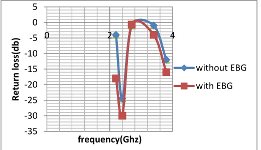
[image:4.612.40.559.312.739.2]Fig 5: Return Loss Vs Frequency with Circular patch
Fig 6: Return Loss Vs Frequency with Square loop
Fig 7: Return Loss Vs Frequency with Circular loop
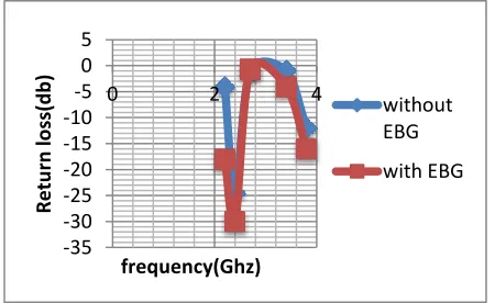
Fig 8: Return Loss Vs Frequency with Square aperture -35 -30 -25 -20 -15 -10 -5 0 5
0 2 4
R e tu rn lo ss(d b ) frequency(Ghz) without EBG with EBG -35 -30 -25 -20 -15 -10 -5 0 5
0 2 4
R e tu rn lo ss(d b ) frequency(Ghz) without EBG with EBG -30 -25 -20 -15 -10 -5 0 5
0 2 4
R e tu rn lo ss(d b ) frequency(Ghz) without EBG with EBG -30 -25 -20 -15 -10 -5 0 5
0 2 4 6
R e tu rn lo ss(d b ) frequency(Ghz) without EBG with EBG -35 -30 -25 -20 -15 -10 -5 0 5
0 2 4
[image:4.612.324.553.314.459.2] [image:4.612.34.259.387.525.2]© 2017, IRJET | Impact Factor value: 5.181 | ISO 9001:2008 Certified Journal | Page 2383 Fig 9: Return Loss Vs Frequency with Cross dipole
Fig 10: Return Loss Vs Frequency with Gridded square frequency selective surface
Fig 11: Return Loss Vs Frequency with Jerusalem cross
RESULTS:
The below given results shows the comparison of the gain between with EBG and without EBG
Table 1: comparison of various performance parameters of different shapes of microstrip patch antenna
Without EBG With EBG
Ante nna Shap es freq uen cy Retu rn loss
gain freq uenc y
Retur n loss Gain
Squar e Patch
2.4 -15 -0.5 2.32 -28 2.60
Circul ar Patch
2.4 -10 1.88 2.33 -21 3.502
Circul ar Loop
2.42 -12 -4.9 2.3 -14 -0.99
Squar e Loop
2.4 -25 5.4 2.5 -28 -1.34
cross dipol e
2.4 -22 -1.2 2.55 -13.5 1.55
squar e apert ure
2.4 -24 0.9 2.4 -17 3.38
jerus alem cross
2.41 -24 -8.2 2.43 -30 -6.41
Gridd ed squar e frequ ency select ive surfa ce
2.42 -10 -4.1 2.2 -16 -3.99
CONCLUSION:
From the simulation analysis of the square patch, circular Patch, circular Loop, square Loop, cross dipole, square aperture, Jerusalem cross , gridded square frequency selective surface microstrip antenna it is observed that at 2.4GHz of operating frequency the square aperture and circular patch gave the best result with obtained higher gain by using Electromagnetic Band Gap(EBG).
-35 -30 -25 -20 -15 -10 -5 0 5
0 2 4
R e tu rn lo ss(d b ) frequency(Ghz) without EBG with EBG -35 -30 -25 -20 -15 -10 -5 0 5
0 2 4
R e tu rn lo ss(d b ) frequency(Ghz) without EBG with EBG -35 -30 -25 -20 -15 -10 -5 0 5
0 2 4
[image:5.612.37.297.277.418.2] [image:5.612.35.295.463.613.2]© 2017, IRJET | Impact Factor value: 5.181 | ISO 9001:2008 Certified Journal | Page 2384 REFERENCES
[1] D. Malbantoglu, and A. Yanik, ‘‘A Multi-Band Rectangular Patch Antenna for Wireless Communication,’’ 2004.
[2] S. K. Behera, ‘‘Design of Linearly Polarized Rectangular Microstrip Patch Antenna using IE3D/PSO , 2009.
[3] A.B.MUTIARA, R.REFIANTI,
RACHMANSYAH.,“Design of microstrip antenna for wireless communication at 2.4 ghz”,2011.
[4] B. J. Kwaha, O. N Inyang & P. Amalu., “The circular microstrip patch antenna – design and implementation”,2011.
[5] J. EL Aoufi, N. Alaoui, M. Essaaidi and M. Benayad, ‘‘Design of a Low Cost Planar Antenna for 2.45 GHz
RFID Applications AIMAC ultra high frequencies laboratory,’’ 2011.
[6] ZaakriSafa, Zenkouar Lahbib, BRI Seddik., “Simulation of a Rectangular Patch Antenna”.,2012. [7] Sanjeev Sharma, Bharat Bhushan, Shailender Gupta and PreetKaur., “ Performance Comparison of Micro-strip Antennas with Different Shape of the Patch”2013
[8] AlakMajumder., “Rectangular Microstrip Patch Antenna Using Coaxial Probe Feeding Technique to Operate in S-Band”.2013.