ii
SIMULATION OF AC-DC CONVERTER FOR DC MOTOR
APPLICATION USING FUZZY LOGIC CONTROL
KHALED ABUBAKER HASSAN SULIMAN
This project report presented in partial fulfillment of the requirements for the award of the Degree of Master of Electrical Engineering
Faculty of Electrical and Electronic Engineering Universiti Tun Hussein Onn Malaysia
ABSTRACT
The AC to DC variable converter becomes an important drive configuration for DC motor applications across a wide range of powers and speeds. Consequently, this converter requires a controller with a high degree of dynamic response. Generally,
vii
ABSTRAK
TABLE OF CONTENTS
TITLE ii
DECLARATION iii
DEDICATION iv
ACKNOWLEDGEMENT v
ABSTRACT vi
TABLE OF CONTENTS viii
LIST OF TABLE x
LIST OF FIGURE xi
LIST OF SYMBOLS AND ABBREVIATIONS xiii
LIST OF APPENDIX xiv
CHAPTER 1 INTRODUCTION
1.1 Project background 1
1.2 Problem statements 2
1.3 Project objectives 3
1.4 Scope of project 4
1.5 Project report layout 4
CHAPTER 2 LITERATURE REVIEW
2.1 Introduction 5
2.2 Rectifier converter 7
ix
2.2.3 Phase angle delay control 13
2.3 Turning on the ACR methods 15
2.4 Turning on the SCR by gate triggering 15
2.5 Dc Motor 15
2.5.1 Separately Excited Machines 16
2.5.2 Self excited machines 17
2.6 Control technique 19
2.6.1 PID Controller 20
2.6.2 Fuzzy logic control 22
2.6.2.1 Rule base 25
2.6.2.2 Advantages of fuzzy logic controller 26 CHAPTER 3 METHODOLOGY
3.1 Project background 27
3.2 Project flow chart 28
3.3 Project block diagram 29
3.4 Ac-dc converter parameter 29
3.5 PID Controller Design for AC-DC Converters 31 3.7 Fuzzy logic controller and its operational methodology 32
3.7.1 Fuzzification 34
3.7.2 Rule base 36
3.7.3 Inference mechanism 36
3.7.4 Defuzzification 37
3.8 Operational the fuzzy logic control for ac-dc converters 37 3.9 Speed control of separately exited dc motor 40 CHAPTER4 RESULT AND ANALYSIS
4.1 introduction 42
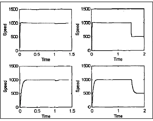
4.2 Step up analysis 42
4.3 Step down analysis 44
4.4 Transient response 47
CHAPTER5 CONCLUSION AND RECOMMENDATION
5.2 Recommendations 51
REFERENCES 52
APPENDIXS 54
LIST OF TABLE
2.1 Example of rule base 25
3.1 The value of all parameters can be determined as below Parameters and values for AC-DC converter feeds DC motor.
30
3.2 3×3 Rules base for error and change of error 36
4.1 The reading on peak overshoot and settling time for step up case (0-1200)rpm
44
4.2 The reading on peak overshoot and settling time for step down case (1200-700)rpm
46
4.3 The reading on peak overshoot and settling time for step up case (700-1100)rpm
xi
LIST OF FIGURE
2.1 Simulation result 6
2.2 Single phase half-wave rectifier 8
2.3 Voltage waveform 8
2.4 The bridge rectifier 9
2.5 The centre-tapped transformer rectifier 10
2.6 Basic half-wave controlled rectifier 11
2.7 Voltage waveform 11
2.8 Basic full-wave controlled bridge rectifier 12
2.9 Voltage wave forms 13
2.10 Circuit modes 14
2.11 Possible Output Voltage waveform For SCR Bridge 14
2.12 Separately excited DC Motor 16
2.13 Shunt dc motor 17
2.14 Series dc motor 18
2.15 Current control loop employing controlled rectifier 20 2.16 Proportional-Integral-Derivative (PID) Controllers 21
2.17 Fuzzy logic control diagram 22
2.18 a) Triangular b) trapezoid membership function 23 2.19 Monotonically increasing linear b) monotonically decreasing
linear membership function
23
2.20 Monotonically increasing sigmoidal b) monotonically decreasing sigmoidal membership function
23
2.21 (a) π, (b) Gaussian membership function 24
2.22 Sugeno Fuzzy Logic Control (FLC) Concept 25
3.1 project flow chart 28
3.2 The block diagram. 29
Simulink
3.4 Simulink Model of the PID Controller for the AC-DC Converters
32
3.5 Block diagram of fuzzy control system 33
3.6 Membership functions of the inputs e[k] 35
3.7 Membership functions of the inputs e[k-1]. 35
3.8 Membership functions of the output δd[k] 35
3.9 Simulink model of the fuzzy logic controller for the ac-dc converters
38
3.10 Flowcharts of fuzzy logic controller for the ac-dc converters 39
3.11 Separately excited DC Motor 40
3.12 Variation of speed with applied voltage 41
4.1 Start up voltage response 43
4.2 Start up speed response comparison between conventional PID and fuzzy controller
43
4.3 Start up armature current response comparison between conventional PID and fuzzy controller
44
4.4 Step down voltage response when the speed reference is varied from 1200-700 rpm
45
4.5 Step down speed response comparison between conventional PID and fuzzy controller when the speed reference is varied from 1200-700 rpm
45
4.6 Step down armature current response comparison between conventional PID and fuzzy controller when the speed reference is varied from 1200-700 rpm.
46
4.7 Step up speed response comparison between conventional PID and fuzzy controller when the speed reference is varied from 700 rpm to 1100 rpm
47
4.8 Step up speed response when the speed reference is varied from700 rpm to 1100rpm
48
4.9 Step up current response comparison between conventional PID and FLC controller for700rpm to1100 rpm
xiii
LIST OF SYMBOLS AND ABBREVIATIONS
- firing angle
ω - Angular speed
Ia - Armature current
IF - Field current
RA - Armature resistance
LA - Armature Inductance
Ke - Electric motor constant
µe - degree of membership function of error
e - error
Δe - of membership function of delta of error
che - Change of error
FLC - Fuzzy logic controller
MF - Membership function
P - Positive
Z - Zero
PS - Positive small
PM - Positive medium
PB - Positive big
N - Negative
LIST OF APPENDICES
APPENDIX TITLE PAGE
CHAPTER 1
INTRODUCTION
1.1 Project Background
The ac to dc converter is an integral part of any power supply unit used in the all electronic equipments. And can be used as an interface between utility and most of the power electronic equipments. These electronic equipments form a major part of load on the utility. Generally, to convert line frequency ac to dc, a line frequency diode bridge rectifier is used. And sometimes a large filter capacitor is used To reduce the ripple in the dc output voltage [1].
And the AC-DC converters serve as rectifiers. They convert ac to dc in a number of industrial, domestic, agricultural, and other applications. Rectifiers are used as stand-alone units feeding signal and multiple dc motor and as input stages of ac drives because of their virtually unlimited output power and fine controllability. Their response is usually adequate to handle electromechanical transient occurring in drives.
function of the mains voltage. To turn on the thyristor , an injection of current pulse into its gate is required [14].
1.2 Problem Statements
Traditionally DC motors were controlled using PID method. However this method generates high overshoot and long settling time.
In order to improve performance of the DC motor drive system a FLC will be proposed. By this reason, the problem statement of this project is how to develop FLC model to apply in DC motor drive. Hence the performance of the speed controller can be improved.
1.3 Project Objectives
The major objectives of this proposal are:
i) To model a regulated AC-DC converter fed DC motor without controller (open loop) and simulate using MATLAB Simulink.
ii) To simulate Proportional-Integral-Derivative (PID) Controllers to control the regulated AC-DC converter to drive dc motor.
iii) To design model fuzzy logic controller (FLC) to control the regulated AC-DC converter to drive dc motor.
1.4 SCOPE OF PROJECT
3
regulated AC-DC converter and the step response of the DC motor speed based on reading on overshoot ratio, rise time, peak time and settling time.
1.5 Project report layout
This project report is organized as follows;
Chapter 1 briefs the overall background of the study. A quick glimpse of study touched in first sub-topic. The heart of study such as problem statement, project objective, project scope and project report layout is present well through this chapter.
Chapter 2 covers the literature review of previous case study of types of AC-DC converters and based on fuzzy logic controller background to control DC motor and development. Besides, also Proportional-Integral-Derivative (PID) Controllers, general information about AC-DC Converter and theoretical revision on fuzzy logic control system also described in this chapter.
Chapter 3 presents the methodology used to design open loop AC-DC Converter feeds DC motor and also closed loop with fuzzy logic controller and Proportional-Integral-Derivative (PID) controllers to drive DC motor. All the components that have been used in designing of fuzzy logic controller are described well in this chapter.
Chapter 4 reports and discuss on the results obtained based on the problem statements as mentioned in the first chapter. The simulation results from PID controller and the proposed of fuzzy logic controller will be analyzed.
CHAPTER 2
LITERATURE REVIEW
2.1 Introduction
The literature review about this project has been made from various sources like journals, books, articles and others. From the literature review, the input that has been collected is useful for better understanding of this project.
S. baskar P.Subbaraj N.M. prakash kumar
Fuzzy Logic and Neural Network concepts are applied to DC drive system. A systematic approach to construct, membership functions of FLC using Shrinking Span Membership Functions (SSMFs), is adopted here [3]. This paper proposes a SSMFs Fuzzy Logic Controller for Current and Speed control loops of DC Drive systems. The digital simulation study of model system is carried out with proposed PI controllers using MATLAB-SIMULINk software.
6
Figure 2.1: Simulation result
Jong-Bae Lee, Tae-Bin Im, Ha-Kyong Sung , Young-Ouk Kim
In this paper, focuses on a low cost speed control system using a fuzzy logic controller for a Brushless DC Motor was explained by [4]. In a digital controller of brushless DC Motor, the control accuracy is of a high level, and it has a fast response time. they used a hall IC signal for the permanent magnet rotor position and for the speed feedback signals, and also for a microcontroller of 8-bit type (80CL580); also designe the fuzzy logic controller and implemented the speed control system of brushless DC Motor. To acquire an accurate fuzzy logic control algorithm, a simulation with the MATLAB program has been made, while the performance of the system, done with an experiment for a unit step response, was also verified.
Mohamed. A. Enany
2.2 Rectifier converter
Rectifier circuits have been the most common power electronics circuits used to convert AC to DC. The AC-DC converter produces a DC output from an AC input while the average power transferred from an AC source to a DC load. This converter usually also called as a rectifier. The word rectification is used not because these circuits produce DC but rather because the current flows in one direction. Generally, there are two types of AC-DC converters which are uncontrolled and controlled. The input of these converters can be single phase or multi-phase (3 phase).
2.2.1 Uncontrolled Single Phase Rectifier
This type of rectifier consists of half-wave rectification and full-wave rectification. Uncontrolled rectifiers make use of diodes. Diodes are two-terminal semiconductor devices that allow flow of current in only one direction. The two terminals of a diode are known as the anode and the cathode. The designs are cheap and popular in the industrial applications. In some of these rectifiers, the AC source from the electric utility is directly rectified without using of an expensive and bulky transformer. In some applications, the DC voltage from the rectifier is connected to a DC bus for distribution to several different circuit systems, subsystems and other converters as loads [2]. In other applications, the rectifiers also supply power to inductive-resistive (motors) and capacitive-resistive (power supplies) loads.
i) Single Phase Half-Wave Rectifiers
8
[image:17.612.201.454.360.470.2]uncontrolled in that the on and off conditions are determined by voltages and currents in the circuit. By using diode, the DC level of the output and the power transferred to the load are fixed when the source and load parameters are established. It produces an output waveform that is half of the incoming AC voltage waveform Figure 2.3. The positive pulse output waveform occurs because of the forward-biased condition of the diode. A diode experiences a forward-biased condition when its anode is at a higher potential than its cathode. Reverse bias occurs when its anode is lower than its cathode. During the positive portion of the input waveform, the diode becomes forward biased, which allows current to pass through the diode from anode to cathode, such that it flows through the load to produce a positive output pulse waveform. Over the negative portion of the input waveform, the diode is reverse-biased ideally so no current flows. Thus, the output waveform is zero or nearly zero during this portion of the input waveform.
Figure 2.2: Single phase half-wave rectifier.
[image:17.612.205.453.529.682.2]ii) Single Phase Full-Wave Rectifiers
The objective of a full-wave rectifier is to produce a voltage or current that is purely dc or has some specified dc component. While the purpose of the fullwave rectifier is basically the same as that of the half-wave rectifier, full-wave rectifiers have some fundamental advantages. The average current in the ac source is zero in the full-wave rectifier, thus avoiding problems associated with nonzero average source currents, particularly in transformers. The output of the full-wave rectifier has inherently less ripple than the half-wave rectifier. [2]
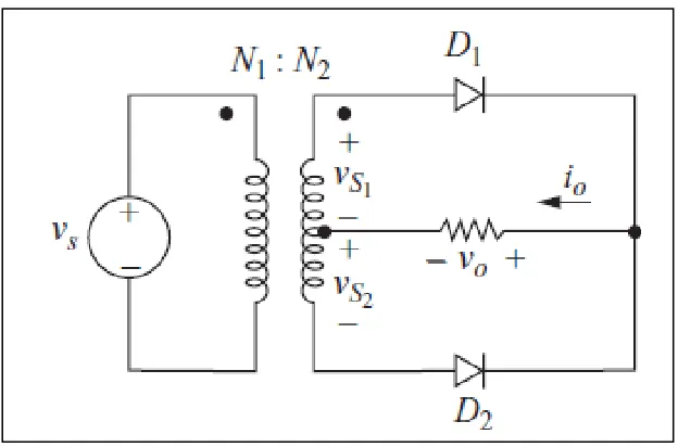
[image:18.612.171.486.372.549.2]There are two types of full-wave rectifiers that are the bridge rectifier and the center-tapped rectifier as shown in Figure 2.4 and Figure 2.5.
10
Figure 2.5: The centre-tapped transformer rectifier
The lower peak diode voltage in the bridge rectifier which consists of four diodes arranged makes it more suitable for high-voltage applications. Thus, the center-tapped transformer rectifier in addition to including electrical isolation has only one diode voltage drop between the source and load making it desirable for low-voltage and high current applications.
2.2.2 Controlled Single Phase Rectifier
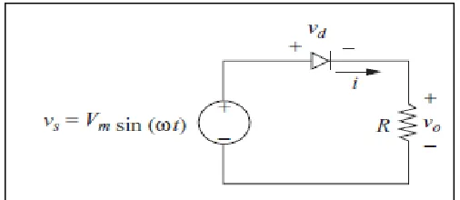
i) Single Phase Half-Wave controlled Rectifiers
[image:20.612.172.488.304.437.2]Unlike the diode, the silicon controlled rectifier (SCR) will not to begin to conduct as soon as the source becomes positive. Gate trigger current is the minimum current required to switch silicon controlled rectifiers from the off-state to the on-state at the specified off-state voltage and temperature. Once the SCR is conducting, the gate current can be removed and the SCR remains on until the current goes to zero. Figure 2.6 shows a basic controlled half-wave rectifier.
Figure 2.6: Basic half-wave controlled rectifier
[image:20.612.170.485.490.673.2]12
ii) Single Phase Full-Wave controlled Rectifiers
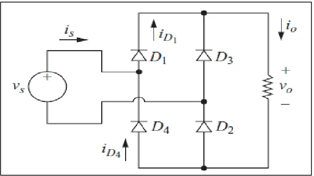
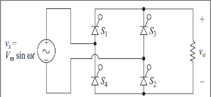
Popular AC-DC converters use full-bridge topologies. Full-bridge converters are designed for delivering constant but controllable DC current or DC voltage to the load. Similar to the diode bridge rectifier topology, a versatile method of controlling the output of a full-wave rectifier is to substitute controlled switches such as SCRs for the diode. Because of their unique ability to be controlled, the output voltage and hence the power can be controlled to desire levels. The triggering of the thyristor has to be synchronized with the input sinusoidal voltage in an AC to DC rectifier circuit.
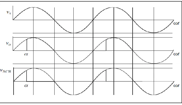
[image:21.612.142.513.444.614.2]The delay angle α is the angle interval between the forward biasing of the SCR and the gate signal application. Otherwise, if the delay angle is zero, the rectifiers behave exactly like uncontrolled rectifiers with diodes. Figure 2.8 shows a basic controlled full wave rectifier.
Figure 2.9: Voltage wave forms.
2.2.3 Phase Angle Delay Control
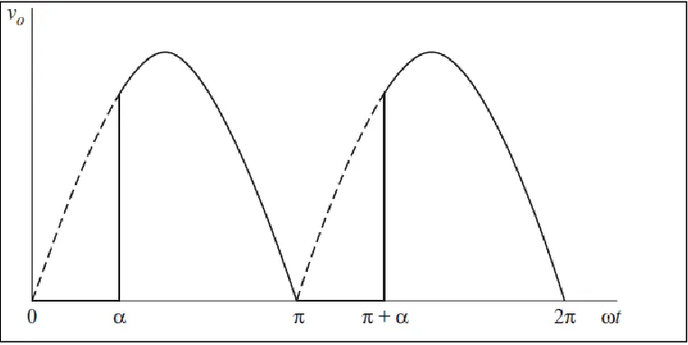
Converter operation in steady-state is best described over a period that begins from the phase α to 2п+ α. This operation involves two circuit modes during a single period of the source waveform depending upon the state of the switches as shown in Figure 2.8. Mode 1 starts when the SCRs T1 and T3 are turned on at an angle α by control pulses applied at their gate terminals. During mode 1, SCRs T1 and T3 are in forward-biased mode and SCRs T2 and T4 are in reverse blocking mode. The current Io flows through the path shown in Figure 2.11. After angle п, the input source voltage become negative but the SCRs T1 and T3 still conducting. Note that the current sink is the model of a high value inductor, voltage across it can change instantaneously but current cannot. Hence, the output voltage, Vo become negative and follows the input voltage, Vs waveform. The input source is supplying power to the load during α to п which is referred also as the rectifier operation.
14
reverse blocking mode. This converter operation in this mode is identical to that mode 1 during the angle from п+α to 2п+α.
There several possible output voltages are shown in Figure 2.11 given duty ratio of 50%. The phase delay angle allows control over the DC output just as duty ratio control permits adjustment of the output in DC-DC converter [8]. Since DC output is of interest and because the output current comes along with a DC source, the average voltage Vo needs to be determined. Its value will be:
[image:23.612.167.489.530.709.2](2.1)
Figure 2.11: Possible output voltage waveform for scr bridge.
2.3 Turning on the ACR methods
Normally can be turn on The SCR by apply pulse to its gate. It can also be turned on by another three alternative methods that include exceeding the forward break over voltage , by excessive heat that allows leakage current , or by exceeding the dv/dt level (allowable voltage change per time change) across the junction. The three alternative methods of turning on an SCR generally cause conditions which should be controlled to prevent the SCR from being turned on when this is not wanted.
2.4 Turning on the SCR by gate triggering
When a positive pulse is applied to the gate of the SCR, it must be large enough to provide sufficient current to the first junction. If the current level of the pulse is sufficient, the first junction will go into conduction and the current flow through it will cause the second junction of the transistor to go into conduction. the current through the second junction will be sufficient to latch up the SCR by supplying an alternative source for the gate current. This means that the current to the gate can be removed and the SCR will remain in conduction. The SCR will commutate when the power supply it is connected to returns to the zero voltage level at 180º or when AC voltage is in reverse polarity (180º to 360º). If the pulse too small that applied to the gate or not enough in duration, the SCR will not turn on [12].
16
DC Machines can be classified according to the electrical connections of the armature winding and the field windings. The different ways in which these windings are connected lead to machines operating with different characteristics. The field winding
can be either self-excited or separately excited, that is, the terminals of the winding can be connected across the input voltage terminals or fed from a separate voltage source (as in the previous section). Further, in self-excited motors, the field winding can be connected either in series or in parallel with the armature winding. These different types of connections give rise to very different types of machines, as we will study in this section.
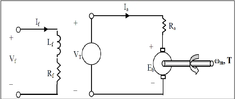
2.5.1 Separately Excited Machines
The armature and field winding are electrically separate from each other.
[image:25.612.126.529.472.641.2] The field winding is excited by a separate DC source.
The voltage and power equations for this machine are same as those derived in the previous section. The total input power = Vf If + VT Ia
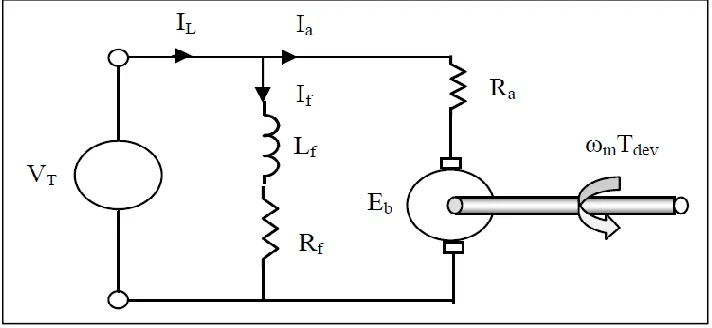
2.5.2 Self Excited Machines
In these machines, instead of a separate voltage source, the field winding is connected across the main voltage terminals.
i) Shunt machine:
The armature and field winding are connected in parallel.
[image:26.612.150.506.438.602.2] The armature voltage and field voltage are the same.
Figure 2.13: Shunt DC motor
In this type of motor, Total current drawn from the supply is:
18
Total input power = VT*IL
ii) Series DC machine
The field winding and armature winding are connected in series.
The field winding carries the same current as the armature winding.
[image:27.612.147.511.390.536.2]A series wound motor is also called a universal motor. It is universal in the sense that it will run equally well using either an ac or a dc voltage source. Reversing the polarity of both the stator and the rotor cancel out. Thus the motor will always rotate the same direction irregardless of the voltage polarity.
Figure 2.14: Series DC motor.
iii) Compound DC Machine
and the shunt field winding is connected in parallel. Two types of arrangements are possible in compound motors:
Cumulative compounding - If the magnetic fluxes produced by both series and shunt field windings are in the same direction (i.e., additive), the machine is called cumulative compound.
Differential compounding - If the two fluxes are in opposition, the machine is differential compound. In both these types, the connection can be either short shunt or long shunt [15].
2.6 Control technique
As part of the feedback control system in electrical drives, it is desirable that the relation between the control signal and the average output voltage is linear especially when a linear controller (such as a PI controller) is employed. As an example Figure 2.15 shows a closed loop current control system for a DC motor drive employing a single phase controlled rectifier. In DC drives (or in other type of electrical drives), it is normally necessary to control the motor current since it is, in most of the cases, proportional to the developed motor torque. This is especially true for a DC motor. The reference current (or reference torque) is compared with actual current and the error is fed to the current controller (e.g. PI controller) to generate the control signal Vc.
20
Figure 2.15: Current control loop employing controlled rectifier
2.6.1 PID Controller
PID stands for proportional, integral, derivative are one of the most popular feedback controller widely use in processing industry. It is easy to understand the algorithm to produce excellent control performance.
Figure 2.16: Proportional-Integral-Derivative (PID) controllers
In designing PID controller there are several steps to be applied in order to obtain desired output response. It is not necessary to implement all three controllers if not needed, if P or PI controller gives a good enough response then there is no need to implement the derivative controller.
Controllers respond to the error between a selected set point and the offset or error signal that is the difference between the measurement value and the set point. Optimum values can be computed based upon the natural frequency of a system. Too 15much feedback (positive feedback cause stability problems) causes increasing oscillation. With proportional (gain) only control the output increases or decreases to a new value that is proportional to the error. Higher gain makes the output change larger corresponding to the error. Integral can be added to the proportional action to ramp the output at a particular rate thus bring the error back toward zero. Derivative can be added as a momentary spike of corrective action that tails off. Derivative can be a bad thing with a noisy signal [6].
Typical steps for designing a PID controller are
i) Determine what characteristics of the system need to be improved. ii) Use KP to decrease the rise time.
22
2.6.2 Fuzzy Logic Control
Fuzzy control is an artificial intelligence technique that is widely used in control systems as shown in Figure 2.17. It provides a convenient method for constructing nonlinear controllers from heuristic information.
Fuzzy controller have achieved some polarity due to the convenient way in which desired nonlinearities may be introduced, especially when no model of the controller process in available but operator experience may be used as a guide to formulating rules. Fuzzy control rule is a fuzzy conditional statement in which the antecedent is a condition in its application domain. In a fuzzy logic controller (FLC), the dynamic behaviour of a fuzzy system is characterized by a set of linguistic description rules based on expert knowledge. The expert knowledge is usually of the form.
IF (a set of conditions are satisfied) THEN (a set of consequences can be inferred).
[image:31.612.215.461.442.590.2]Since the antecedents and the consequents of these IF-THEN rules are associated with fuzzy concepts (linguistic terms), they are often called fuzzy conditional statements.
Figure 2.17: Fuzzy logic control diagram
Membership function of FLC is explained as below:
µA :X [0, 1]
[image:32.612.189.469.113.251.2]a) b)
Figure 2.18: a) Triangular membership function b) Trapezoid membership function
[image:32.612.189.468.295.418.2]a) b)
Figure 2.19: a) Monotonically increasing linear membership function b) monotonically decreasing linear membership function.
a) b)
[image:32.612.185.467.489.617.2]24
[image:33.612.172.485.69.221.2]a) b)
Figure 2.21: a) π membership function, b) Gaussian membership function
A typical rule in a Sugeno fuzzy model has the form
If Input 1 = x and Input 2 = y, then Output is z = ax + by + c
For a zero-order Sugeno model, the output level z is a constant (a=b =0).
The output level zi of each rule is weighted by the firing strength wi of the rule. For example, for an AND rule with Input 1 = x and Input 2 = y, the firing strength is
F x F y
Andmethod
wi 1 , 2 (2.1)
Where F1,2 (.) are the membership functions for Inputs 1 and 2.
The final output of the system is the weighted average of all rule outputs, computed as:
N i i N i i i w z w t FinalOutpu 1 1 (2.2)Where N is the number of rules.
REFERENCES
[1] A. K. Jha,& B. G. Fernandes and A. Kishore. (2006). A Single Phase Single Stage AC/DC Converter with High Input Power Factor and Tight Output Voltage
Regulation. Indian Institute of Technology. India. pp:322-329.
[2] Daniel.W. Hart. (2011). Power Electronics, New York: McGraw-Hill.
[3] Jantzen. J (1998 ). Design Of Fuzzy Controllers .Technical University of Denmark: Tech. report.
[4] Lee, J.B; Im, T. B; Sung , H. K; Kim. Y. O. (1999). A low cost speed control system of brushless dc motor using fuzzy logic, Proceedings Information Decision
and Control. pp:433-437.
[5] K. B. Mohanty.(2004). Fuzzy remote controller for converter DC motor drives, Paritantra, Vol. 9. pp: 1-7.
[6] M.J. Willis,(1999) . Proportional-Integral-Derivative Control, University of Newcastle.
[7] Enany ,M. A..(2010). Effects of Single Phase AC/DC Converter Drive on the Torque-Speed Characteristic of DC Motor, International Middle East Power Systems
Conference, Egypt, pp: 782-285.
[8] Robbins , M. U. (2003) . power electronic converters application and design, John Wileys and Sons Inc.
[9] Rehman, H. (2004). Fuzzy logic enhanced robust torque controlled induction motor drive system. IEE Proceedings of control theory and Applications, vol. 151.issue 6.
53
[10] S.Bkar ,& P.Subbaraj and N.M.Prakash kumar, (1998). SSMFs fuzzy logic control and neural network based alpha compensation of phase controlled rectifier fed dc drives,
Power Electronic Drives and Energy Systems for Industrial Growth . pp: 403-408. [11] S. Yuvarajan, & Khoei. A and Kh. Hadidi.(1998) . Fuzzy logic DC motor controller
with improved performance, Industry application conference, Vol. 3, pp: 1652-1656.
[12] Sen, T. & Bhattacharjee, P. K. (2011). Design and Implementation of Firing Circuit for Single-Phase Converter, International Journal of Computer and Electrical
Engineering. Vol. 3, No. 3. pp: 368-374.
[13] Wijaya,T. A. H. (2002). Remote fuzzy logic control system For a DC motor speed control, Journal Teknik Elektro Vol. 2, No. 1.pp: 8-12.
[14] Vodovozov,V & Vinnikov. D (2008) . Electronic systems of motor drive. Estonia: Tallinn university of technology.
[15] S. K Patel, D. S.Efficient (2013). Efficient Harmonics Reduction Based Three Phase H Bridge Speed Controller for DC Motor Speed Control using Hysteresis Controlled
Synchronized Pulse Generator. International Journal of Advanced Research in