6
Reactive Power Compensation Technique By Using STATCOM
Device
Miss.Anuja S.nalkande1, Prof.K.A.Dongre 2, Prof.P.R.Jawale3
Department of Electrical Engineering1,2,3, Students of PLITMS Buldana1, , Assistant Prof. PRMCOE Badnera,2, Assistant Prof. PLITMS,Buldana,3 Email: [email protected]1 ,[email protected]2
Abstract: This paper presents a study on STATCOM (Static synchronous compensator) for reactive power compensation. The STATCOM can be used to improve power quality, power factor, system voltage profile, reactive power compensation FACTS devices can be connected to a transmission line in various ways, such as in series, shunt, or a combination of series and shunt. Shunt FACTS devices are used for controlling transmission voltages, power flow, reducing reactive losses, and damping of power system oscillations for high power transfer levels. A static synchronous compensator (STATCOM) is a regulating device used on alternating current electricity transmission networks. It is based on a power electronics voltage-source converter and can act as either a source or sink of reactive AC power to an electricity network. Usually a STATCOM is installed to support electricity networks that have a poor power factor and often poor voltage regulation. The major attributes of STATCOM are quick response time, less space requirement, optimum voltage platform, higher operational flexibility and excellent dynamic characteristics under various operating conditions. This thesis explains conventional way of compensation and compensation using STATCOM. Operating principle, circuit configuration, switching technologies and implementation of STATCOM at various places are defined in this paper.
Keywords - STATCOM, Reactive Power Compensation.
1. INTRODUCTION
Power Generation and Transmission is a complex process, requiring the working of many components of the power system in tandem to maximize the output. One of the main components to form a major part is the reactive power in the system. It is required to maintain the voltage to deliver the active power through the lines. Loads like motor loads and other loads require reactive power for their operation. To improve the performance of ac power systems, we need to manage this reactive power in an efficient way and this is known as reactive power compensation. There are two aspects to the problem of reactive power compensation: load compensation and voltage support. Load compensation consists of improvement in power factor, balancing of real power drawn from the supply, better voltage regulation, etc. of large fluctuating loads. Voltage support consists of reduction of voltage fluctuation at a given terminal of thetransmission line. Two types of compensation can be used: series and shunt compensation. These modify the parameters of the system to give enhanced VAR compensation. In recent years, static VAR compensators like the STATCOM have been developed. These quite satisfactorily do the job of absorbing or generating reactive power with a faster time response and come under Flexible AC Transmission Systems (FACTS). This allows an increase in transfer of apparent power through a transmission line, and much better stability by the adjustment of parameters that govern the power system i.e. current, voltage, phase angle, frequency and impedance.
Micro grid is a Small Scale Power Supply Network to provide Power for a Small Community. It is used for local
Power Generation for local loads. It uses highly Flexible and efficient Small Power Generating sources. It is connected to both
the local generating units and the utility grid thus preventing power outages. Excess power can be sold to the utility grid. Size of the Micro grid may range from housing estate to municipal regions.
Micro grid is a localized grouping of electricity sources and loads that normally operates connected to and synchronous with the traditional centralized electrical grid(macro grid), but can disconnect and function autonomously as physical and/or economic conditions dictate. By this way, it paves a way to effectively integrate various sources of distributed generation (DG), especially Renewable Energy Sources (RES). It also provides a good solution for supplying power in case of an emergency by having the ability to change between islanded mode and grid-connected mode. On the other hand, control and protection are big challenges in this type of network configuration, which is generally treated as a hierarchical control.
2. REACTIVE POWER
7
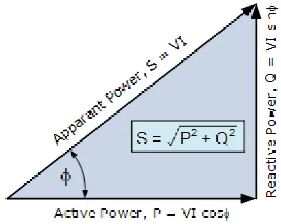
energy is stored temporarily in inductive and capacitive elements, which results in the periodic reversal of the direction of flow of energy between the source and the load. The average power after the completion of one whole cycle of the AC waveform is the real power, and this is the usable energy of the system and is used to do work, whereas the portion of power flow which is temporarilystored in the form of magnetic or electric fields and flows back and forth in the transmission line due to inductive and capacitive network elements is known as reactive power. This is the unused power which the system has to incur in order to transmit power.
Fig -1: Power Triangle
Inductors (reactors) are said to store or absorb reactive power, because they store energy in the form of a magnetic field. Therefore, when a voltage is initially applied across a coil, a magnetic field builds up, and the current reaches the full value after a certain period of time. Capacitors are said to generate reactive power, because they store energy in the form of an electric field. Therefore when current passes through the capacitor, a charge is built up to produce the full voltage difference over a certain period of time. Thus in an AC network the voltage across the capacitor is always charging. Since, the capacitor tends to oppose this change; it causes the voltage to lag behind current in phase.
2.1 Need Of Reactive Power
Voltage control in an electrical power system is important for proper operation for electrical power equipment to prevent damage such as overheating of generators and motors, to reduce transmission losses and to maintain the ability of the system to withstand and prevent voltage collapse. In general terms, decreasing reactive power causing voltage to fall while increasing it causing voltage to rise.
A voltage collapse occurs when the system try to serve much more load than the voltage can support. It is required to generate
energy in a more efficient, reliable and cost effective way. Effective way of delivering electrical energy utilizes technologies like FACTS (Flexible AC transmission system), SVC (Static voltage compensation), etc. to maintain voltage stability, high power factor and less transmission losses. Reactive power plays crucial role in the power system network. AC power supply system’s produce and consume two types of powers; active and reactive power. Real power or active power is the true power given to any load. It accomplishes useful work like lighting lamps, rotating motors, etc. On the other hand reactive power is the imaginary power or apparent power, which does not do any useful work but simply moves back and forth in the power system lines. It is a byproduct of AC systems and produced from inductive and capacitive loads. It exists when there is phase displacement between voltage and current. It is measured in units of volt-ampere reactive (VAR).
Need Of Compensation
The main reason for reactive power compensation in a system is:
The voltage regulation
Increased system stability
Better utilization of machines connected to the system
Reducing losses associated with the system
To prevent voltage collapse as well as voltage sag.
Reactive power generated by the ac power source is stored in a capacitor or a reactor during a quarter of a cycle and in the next quarter of the cycle it is sent back to the power source. Therefore the reactive power oscillates between the ac source and the capacitor or reactor at a frequency equals to two times the rated value (50 or 60 Hz). So to avoid the circulation between the load and source it needs to be compensated. Also to regulate the power factor of the system and maintain the voltage stability we need to compensate reactive power.
Type of Compensation
There are five types of compensations used which are explained below:
Shunt Compensation
8
Therefore we can see that, a current source or a voltage source can be used for both leading and lagging shunt compensation, the main advantages being the reactive power generated is
Independent of the voltage at the point of connection.
Fig -3.1: Transmission line with shunt compensation
2.1 Series Compensation
In a transmission system, the maximum active power transferable over a certain power line is inversely proportional to the series reactance of the line. Thus, by compensating the series reactance to a certain degree, using a series capacitor, an electrically shorter line is realized and higher active power transfer is achieved. Since the series capacitor is self-regulated, i.e. its output is directly (without control) proportional to the line current itself, it will also partly balance the voltage drop caused by the transfer reactance. Consequently the voltage stability of the transmission system is increased..
Fig -3.2: Transmission line with series compensation
3.3 Synchronous Condensers
Power factor correction is becoming a greater concern for industrial and manufacturing plants all around the world. Power Systems & Controls Series SC is the answer to correcting power factor problems and avoiding costly demand
charges. PS&C’s Synchronous Condenser can easily
correct power factor correction issues as it delivers the required reactive power (KVAR) dynamically by being connected to the utility as the continuous reference source for correction. The condenser will adjust the excitation level automatically to maintain the power factor at the desired power factor/KVAR. The synchronous condenser is critical for any facility’s overall power quality as it reduces voltage transients, creates a smoother sine waveform, and reduces the problems associated with harmonic distortion.
3.4 Static VAR compensators
The main advantage for using a topology with TSC branch (es) is to reduce the losses (by reducing the filter size). Mechanically switched banks can be included both on HV and LV side of SVC transformer to increase the total reactive power support outside the dynamic range. ABB SVC control system can be utilized for controlling new or existing external shunt banks. Static VAR compensator has no rotating parts and is employed for surge impedance compensation and compensation by sectionalizing a long transmission line.
Advantages:
Static VAR compensation is not done at line voltage;
a bank of transformers step the transmission voltage (for e.g. 230 kV) down to much lower level (for e.g. 9.5kv). This reduces size and number of components.
They are more reliable
Faster in operation
Smoother control and more flexibility can be
provided with the help of thyristor.
Fig -3.2: Static VAR compensators
3.5 Static Compensator
9
3. STATICCOMPENSATOR:STATCOM
One of the many devices under the FACTS family, a STATCOM is a regulating device which can be used to regulate the flow of reactive power in the system independent of other system parameters. STATCOM has no long term energy support on the dc side and it cannot exchange real power with the ac system. The static synchronous compensator is used in power system network for improving voltage of a particular bus and compensates reactive power. It is connected to a bus near to source to improve the voltage profile and reactive power compensation.
STATCOM or Static Synchronous Compensator is a shunt device, which uses force-commutated power electronics (i.e. GTO, IGBT) to control power flow and improve transient stability on electrical power networks. It is also a member of the so-called Flexible AC Transmission System (FACTS) devices. The term Static Synchronous Compensator is derived from its capabilities and operating principle, which are similar to those of rotating synchronous compensators (i.e. generators), but with relatively faster operation.. STATCOMs are typically applied in long distance transmission systems, power substations and heavy industries where voltage stability is the primary concern.
Fig -4.1: STATCOM
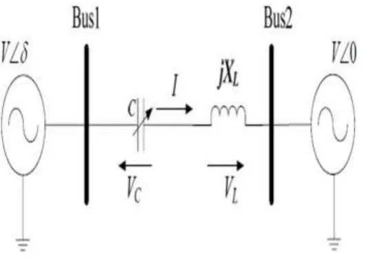
From the d.c. side capacitor, a three phase voltage is generate by the inverter. This is synchronized with the a.c supply. The link inductor links this voltage to the a.c supply side. This is the basic principle of operation of STATCOM. For two AC sources which have the same frequency and are connected through a series inductance, the active power flows from the leading source to the lagging source and the reactive power flows from the higher voltage magnitude source to the lower voltage magnitude source. The phase angle difference between the sources determines the active power flow and the voltage magnitude difference between the sources determines the reactive power flow. Thus, a STATCOM can be used to regulate the reactive power flow by changing the magnitude of the VSC voltage with respect to source bus voltage.
Fig -4.2: Transmission Line Network
The 6 bus system shown above describes a transmission line network. The load data, voltage magnitude, generation schedule, and the reactive power limits for the buses are tabulated in the appendix. Bus 1, with a voltage specified as, is taken as the slack bus, and accounts for all the losses associated with the transmission line as well as the generators. The base MVA is taken 54 as 100 MVA. All the resistances, reactance’s, susceptances and other parameters are calculated on the basis of this MVA. First we analyze the system without the implementation of a STATCOM and see the results of the fault at different buses and removing different lines. Then we compare the graphs of the different buses with their respective faults, and find out the point where it would be best suited to implement a STATCOM. Thereafter we analyze the system with a STATCOM and check out the improvement if any. The transient stability due to the sudden fault at any point is analyzed.
Case 1: Using Hadi Sadat power system analysis toolbox, we analyze the 6 bus system and for fault at bus 6 with (5,6) being the lines removed, we get
10
Case 2: Similarly, we analyze for fault at bus 1 by removing lines (1,4) for the same simulation time and fault clearance time.
Case 3: Fault at bus 4, lines removed are (4, 6)
Case 4: Fault at 6, lines removed are (1, 6)
Case 5: Fault at 5, lines removed are (1, 5)
Therefore we find out that fault at bus 5 causes the maximum excursion of rotor angle of Generator 2 and 3 with respect to Generator 1. The angle of mismatch varies much in this case and it deviates much compared to the previous cases. Thus it would be an appropriate point for the implementation of STATCOM. Hence we put the STATCOM in shunt with the bus 5, and the value of STATCOM reactive power is assumed to be 30 MVAr. Thus the bus 5 and STATCOM together have a total reactive power of 60 MVAr.
11
Next we find from the graphs that the bus system without and with STATCOM and see the difference in rotor angle characteristics. Improved rotor angles can be seen from both the graphs and the implementation of STATCOM has made the transient characteristics much better.
The above graph shows the difference between the behaviors of the system with faults at all the connected buses without and with the STATCOM. We can see that the waveform of the rotor angle of generator 3 with respect to generator 1 shows much better characteristics with the STATCOM and the harmonics are removed due to its action.
4. TECHNICALFEAUTURES
Provides fast smooth dynamic compensation from inductive to capacitive in reactive power. Also eradicates reactive power delivery to the power grid. It meets the maximum request to compensate power factor, keeps power factor close to 1.0 at any time.
Low power loss, better economical operation.
Has powerful ability to support voltage and ability to withstand short-time overload. Provide better support for improving low voltage ride through (LVRT) characteristic for wind turbine. Decrease negative influence which caused by repetitive switching operation to the wind turbine
.
Faster response time and better effect for restraining flicker.
Produce no harmonic and filtering partial load harmonic without amplifying harmonic and no harmonic resonance. It has better safety and stability due to it is not sensitive to the system parameters.
Less space for installation, also provides flexible installation, equipment can be installed indoor/outdoor.
6.CONCLUSION
The study of the basic principles of the STATCOM is carried out as well as the basics of reactive power compensation using a STATCOM. A power flow model of the STATCOM is attempted and it is seen that the modified load flow equations help the system in better performance. The bus system shows improved plots and the thus we can conclude that the addition of a STATCOM controls the output of a bus in a robust manner.
REFERENCES
[1] C. L. Wadhwa, Electrical Power Systems, New Age International Publishers, 2009
[2] Hadi Sadat, Power System Analysis, WCB McGraw Hill, 1999.
[3]Narain Hingorani & L. Gyugi,Understanding FACTS, Concepts and Technology of Flexible AC Transmission Systems, IEEE Press, 2000.
[4] Vireshkumar G. Mathad, Basangouda F. Ronad, Suresh H. Jangamshetti “Review on Comparison of FACTs Controllers for Power System Stability Enhancement” International Journal of Scientific and Research Publications, ISSN 2250-3153, Volume 3, Issue 3, March 2013.