Design and Analysis of Gating System for
Casting Using Simulation Software in
Foundry Industry
Swapnil L. Kolhe1, Prof. S. N. Aloni2, S. K. Chouksey 3
M.Tech (CAD/CAM) IV th Sem Student, Department of Mechanical Engineering, DMIETR, Salod(H), Wardha India 1
Associate Professor, Department of Mechanical Engineering, DMIETR, Salod(H), Wardha India 2
Plant Head, (Jaiswal NECO Industries Ltd.), Hingna, Nagpur, India 3
ABSTRACT
:
The presence of defects is of major concern in the production of castings. Some defects are merely an aesthetic problem while others can be detrimental for the performance of the component.In India most of the foundries are following traditional approach ,based on trial-and-error method for casting development which in turns causes high rejection rate as well as time required for development. It is needless to mention that the Indian Foundry Industry has been identified as one of the major thrust area where the needs of technology transfer and absorption is considered as priority..
KEYWORDS: Casting defects, casting simulation, rejection rate, autocast etc.
I. INTRODUCTION
Although the benefits of casting simulation are well known, its penetration in indian industry continues to be poor. The main bottlenecks are high cost of simulation software, coupled with the unavailability of qualified manpower, and technical support from the vendors. The accuracy of results (such as solidification time and location of shrinkage defects) is influenced by metallurgical models and availability of temperature-dependent material property database. The methoding or rigging feeder and gating design) has to be decided by the user, followed by solid modelling, which requires foundry experience and cad skills. The simulation of intricate castings may involve more time and cost than shop-floor trials, and any error in program inputs implies further delay and expenses. For wider penetration in the industry, casting simulation programs need to be easy-to-use (implying shorter training programmes), reliable (matching of predicted results with actual observations), economical (simulation cost per casting lower than shop floor trials), and well-supported by the vendors (assistance in difficult projects). Casting is a process which carries risk of failure occurrence during all the process of accomplishment of the finished product. Hence necessary action should be taken while manufacturing of cast product so that defect free parts are obtained. Mostly casting defects are concerned with process parameters. Hence one has to control the process parameter to achieve zero defect parts. For controlling process parameter one must have knowledge about effect of process parameter on casting and their influence on defect.
II. LITERATURE REVIEW
ISSN(Online) : 2319-8753 ISSN (Print) : 2347-6710
I
nternational
J
ournal of
I
nnovative
R
esearch in
S
cience,
E
ngineering and
T
echnology
(An ISO 3297: 2007 Certified Organization)
Vol. 5, Issue 7, July 2016
[2] DR. B. RAVI, “Steel Casting Simulation: Live !”, The bottlenecks and non-value added time in casting development can be minimized by adopting CAD, intelligent methoding and simulation technologies .The simple and logical user interface greatly improved the learning curve for engineers, to just a few hours. As a result, even small foundries with little or no previous exposure to CAD/CAM software are able to effectively use the program to improve their casting quality, yield and productivity.
[3] RAJESH RAJKOLHE, J. G. KHAN, “Defects, Causes and Their Remedies in Casting Process: A Review”, In this paper an attempt has been made to list different types of casting defects and their root causes of occurrence. This paper also aims to provide correct guideline to quality control department to find casting defects and will help them to analyze defects which are not desired.
[4] DR. B. RAVI, “Casting Design Optimization driven by Simulation” This papers gives the clear ideas on implementation of casting simulation software with better results. It involves critical decisions regarding part orientation in mold, parting line, cores, cavity layout, feeders, and gating system.
[5] VIVEK S.GONDKAR, K .H. INAMDAR, “Optimization of Casting Process Parameters through Simulation”, This paper focused on best practices, based on studies of industrial cases of casting defect prediction and feeding system optimization, are presented. Current research directions include integration of basic and advanced simulation techniques, useful for large foundries; and cloud-based simulation, useful for SME foundries.
[6] P. PRABHAKARA RAO , G. CHAKRAVERTHI, A.C.S. KUMAR, B. BALAKRISHNA, “Application of Casting Simulation for Sand Casting of a Crusher Plate ”, This paper discusses a newly developed simulation tool and its application to a crusher component that was prototyped via sand casting route.
[7] BINU BOSE V, K N ANILKUMAR, “Reducing rejection rate of castings using Simulation Model”, Rejection rate is one of the major issues in Indian foundry. Foundries try to reduce rejection by experimenting with process parameters or modifying method and tooling design which reduces the quality of castings and increase cost of production. By replacing the existing trial and error method with computer simulation foundries can reduce the rejection rate from 8.5 to 3.5 %. The paper titled “Reducing rejection rate of castings using Simulation Model” is aimed at reducing rejection rate of castings in an Indian foundry.
III. CASE STUDY FROM INDUSTRY
At the time of investigation in NECO Jaiswal Foundry Industry, Hingna MIDC, Nagpur, I had selected one in- line producing component named Socket cap 420 KN. Socket cap 420 KN is a cap of electrical insulator which is used in high tension line such as railway line. Main customer of this component is BHEL, Production of this component has been started in March 2008 and due to large demand it is in process up till now. Requirement of this component is about 70000-80000 per month. It may vary as per the demand of BHEL. After investigation I came on conclusion that rejection rate of this component through Manual or Traditional casting process is 7% and with the help of Autocast (Casting Simulation software to design gating system with lesser defects) rejection rate comes down to 2.5%. Selling price of socket cap 420 KN is 62Rs./Kg. Through investigation, collected some information regarding socket cap 420 KN
Fig. 2:- Cope of Gating system of Socket cap 420 KN Fig.3:- Drag of Gating system of Socket cap 420 KN
Fig. 4:-6*6 methoding of Socket cap 420 KN after solidification
At the time of investigation in industry, I came to know that rejection rate by traditional casting is more because of defects in casting such as shrinkage porosity and blowholes. These defects are observed inside the component and proven to be the major reason of enhancement in rejection rate. So I had suggested them to go with the Autocast-X software to design gating system eliminating defects and then proceed production through manual process.
IV. SIMULATION OF SOCKET CAP 420 KN
IV.I. CASTING SIMULATION PROGRAMS
The casting simulation programs are used for analysing: i. Mould filling
ii. Casting solidification
iii. Internal stresses and distortion
iv. Microstructure and mechanical properties
The simulation programs are based on Finite Element Analysis of 3D models of castings and involve sophisticated functions for user interface, computation and display.
ISSN(Online) : 2319-8753 ISSN (Print) : 2347-6710
I
nternational
J
ournal of
I
nnovative
R
esearch in
S
cience,
E
ngineering and
T
echnology
(An ISO 3297: 2007 Certified Organization)
Vol. 5, Issue 7, July 2016
profile, velocity vectors or residual stresses. This enables predicting the probable location of defects. The results are reliable if the input data is complete and accurate.
The casting design software developed at IITB named AutoCAST is getting popular because of the key features of it such as
i. Part volume, weight, surface area
ii. Part dimensions, as well as its height in cope and drag iii. Wall thickness: minimum, average
iv. Significant modulus around a hot spot v. Casting orientation in the mold vi. Suitable position of the parting line vii. Suitable location of feeder and gates
First simulation of old feeding and gating system of socket cap 420KN component is carried out. Due to that, hot spots are detected. Hence we got shrinkage porosity defect caused by old gating system. Fig.6 shows areas of shrinkage porosity in socket cap 420KN component while simulation of old gating system is carried out.
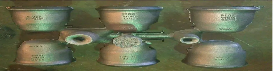
Fig.5:- Parts with shrinkage porosity defect
Fig.6:- After attaching Sleeves
As soon as introduced exothermic sleeves in gating system, shrinkage porosity defect gets eliminated and we can get defects free casting of socket cap 420 KN component.
IV. II. REPORT of Socket cap 420 KN
Layout Name 3 Date and Time 14 Feb 16, 05:58 PM
Cast Metal Ductile Iron - DI Ferrite Casting Process Sand Casting
Density 6900 kg/m³ Liquidus 1161 ºC
ISSN(Online) : 2319-8753 ISSN (Print) : 2347-6710
I
nternational
J
ournal of
I
nnovative
R
esearch in
S
cience,
E
ngineering and
T
echnology
(An ISO 3297: 2007 Certified Organization)
Vol. 5, Issue 7, July 2016
Part
Dimensions 360 mm X 339.69 mm X 157.33 mm Part Surface Area 5193.49 cm²
Min. Thickness 1.8 mm Max. Thickness 14.09 mm
Part Weight 20.17 kg Part Volume 2840.46 cm³
Mold
Mold Material Green Sand Density 1550 kg/m³
Dimensions 700 mm X 600 mm X 360 mm Parting Orientation Horizontal
Number of Cavities x Draw Distance N/A
Min. Cavity-Wall Gap 170 mm Metal / Sand (weight) 9.86 %
Min. Cavity-Cavity Gap N/A Metal / Sand (Volume) 2.15 %
Feeders
Total Feeding Weight 2.46 kg Feeding Yield 89.11 %
Feeder 1
Orientation Side Shape SphericalBottom
Weight 2.46 kg Volume 347.17 cm³
Diameter Top 50 mm Diameter Bottom 60 mm
Height 100 mm Number of Necks 4
Neck 1
Shape Cylindrical Length 31.1 mm
Diameter at Part 20 mm Diameter at Feeder 40 mm
Neck 2
Shape Cylindrical Length 28.74 mm
Diameter at Part 20 mm Diameter at Feeder 40 mm
Neck 3
Shape Cylindrical Length 35.48 mm
Diameter at Part 20 mm Diameter at Feeder 40 mm
Neck 4
Shape Cylindrical Length 31.26 mm
Diameter at Part 20 mm Diameter at Feeder 40 mm
Costing
Tooling Cost 108 Rs Energy Cost 96 Rs
Cast Metal Cost 979 Rs Labor Cost 264 Rs
Indirect Material Cost 246 Rs Total Process Cost 359 Rs
V. RESULTS
The following advantages we gained by using AutoCAST software for the design of methoding for casting. i. The time required is very less as compared to the conventional method of design of methoding.
ii. Number of options were made available to suitably select the same.
iii. The cost was much lower as compared to the conventional trial and error method.
iv. Visualization of mold filling phenomenon makes the process easy to understand to the user. v. Hot spots were easily located where probable chance of occurrence of defect was more. vi. The key parameters of the process were identified easily.
vii. The rejection due to the defects arising out of methoding design was reduced to some extent.
The results also includes-- Improved casting quality Reduction in rejection Reduced cost of rejection Reduced lead time Increased efficiency Increased yield
Along with the above advantages following points are important which add to the merit.
i. Product designers can evaluate castability and improve part designs before releasing for manufacture, leading to overall quality and cost improvement.
ii. Foundry engineers can optimize methoding and process parameters to achieve high quality and yield without expensive shop floor trials.
VI.CONCLUSION
Computer simulation modeling is a well-established technology. Initial applications demonstrated the validity and utility of modeling, but further progress was hampered by the primitive state of technology and the expense of building and running the models. Although vast improvements in technology over the past 10 years have greatly reduced the cost of simulation, there are still costs associated with data collection, model building, and validation. To us, these costs seem small in relation to the benefits that can be gained by routinely applying computer simulation modeling to improve metal casting process. AutoCast-X is one of the powerful simulation software on which simulation of Socket Cap 420 KN component have done.Due to simulation on AutoCAST-X software, traditional gating system of Socket Cap 420 KN component has changed into new gating system. Cost of new gating system is less as compared to traditional gating system. Change in feeder location causes minimization of hot spots. Due to simulation of Socket Cap 420 KN component, shrinkage porosity defect gets eliminated because it is method related defect. Rejection rate of casting product has major impact on profit of the company. By traditional casting process rejection rate was about 7% and with the help of casting simulation process it is about 2.5%.. Visualization of mold filling phenomenon makes the process easy to understand to the user.
REFERENCES
[1] [DR. B. RAVI, “Casting Simulation and Optimization: Benefits, Bottlenecks, and Best Practices”, Technical Paper for Indian Foundry Journal, January 2008 , page no.1
[2] DR. B. RAVI, “Steel Casting Simulation: Live !”, Technical Paper for Presentation at STEEL CAST TECH, IIF Vadodara, 24-25 August 2007,page no.1
ISSN(Online) : 2319-8753 ISSN (Print) : 2347-6710
I
nternational
J
ournal of
I
nnovative
R
esearch in
S
cience,
E
ngineering and
T
echnology
(An ISO 3297: 2007 Certified Organization)
Vol. 5, Issue 7, July 2016
[4] V.V.MANE, AMIT SATA AND M. Y. KHIRE, New Approach to Casting Defects Classification and Analysis Supported by Simulation [5] BINU BOSE V, K N ANILKUMAR, “Reducing rejection rate of castings using Simulation Model”, International Journal of Innovative Research in Science, Engineering and Technology Volume 2, Special Issue 1, December 2013
[6] RAJESH RAJKOLHE, J. G. KHAN, “Defects, Causes and Their Remedies in Casting Process: A Review”, International Journal of Research in Advent Technology, Vol.2, No.3, March 2014
[7] P. PRABHAKARA RAO , G. CHAKRAVERTHI, A.C.S. KUMAR, B. BALAKRISHNA, “Application of Casting Simulation for Sand Casting of a Crusher Plate, International Journal of Thermal Technologies, Vol.1, No.1 (Dec. 2011)
[8] D. Joshi and B.Ravi, “Classification and Simulation based Design of 3D Junctions in Casting” Technical Paper submitted to Transactions of the AFS, Oct 1996, pp.8-10.
[9] H.C.Pandit and S.M.Ingale, “Casting Optimization Aided By Simulation”, International Conference on Sunrise Technologies,13th – 15th Jan 2011, pp.4-7.
[10] B.Ravi, R.C.Creese and D.Ramesh, “Design for Casting – A New Paradigm for Preventing Potential Problems”, Transactions of the American Foundry Society, 107, 1999, pp.3-4.
[11]. “Review of Casting Defect Analysis to Initiate the Improvement Process”A.P.More, Dr.R.N.Baxi, Dr.S.B.Jaju Mechanical Engineering Department, G.H.Raisoni College of Engineering, Nagpur. 440016 (India)