Microstructure Evolution of Dual-Directional-Extruded Mg Alloy AZ31:
An Experimental and Simulation Study
Liwei Lu
1;2, Tianmo Liu
1;2;*, Yong Chen
1;2, Liguang Wang
3;*and Zhongchang Wang
41
College of Materials Science and Engineering, Chongqing University, Chongqing 400044, P. R. China
2National Engineering Research Center for Magnesium Alloys, Chongqing University, Chongqing 400044, P. R. China
3School of Science, Jiangnan University, Wuxi 214122, P. R. China
4WPI Research Center, Advanced Institute for Materials Research, Tohoku University, Sendai 980-8577, Japan
Combining the finite-element analytic technique with the microscopic observation, we have investigated microstructures and stress-strain distributions of the Mg alloys AZ31 processed by a new extrusion method, dual-directional extrusion. We have found that grains in the extruded alloys are refined significantly, which is attributed to the deformation-induced grain subdivision and dynamic recrystallization. Such well refined grains play a critical role in the enhancement of the long-standing poor mechanical properties of the relevant engineering Mg alloys AZ31.
[doi:10.2320/matertrans.M2010198]
(Received June 7, 2010; Accepted August 23, 2010; Published October 6, 2010)
Keywords: magnesium alloys, dual-directional extrusion, microstructure
1. Introduction
Owing to their low density, magnesium alloys are promising for replacing steel and other high-weight materials in a variety of engineering applications.1–4)One of the most critical issues currently limiting their widespread uses is the restrained ductility and strength, which are intrinsically due to their well-known hexagonal-close-packed structure and low stacking fault energy. To improve these poor mechanical properties, a large number of methods have been attempted, within which the equal-channel angular extrusion (ECAE) technique has been demonstrated to be effective.5–8) The philosophy behind this approach is that the ECAE enables a generation of ultrafine grains in bulk materials without significant residual porosity and volume change. However, this approach generally requires multi-passes till grains are refined, thereby causing a complexity in the industrial proc-essing of Mg alloys.9–11)In this work, we propose a new dual-directional extrusion (DDE) technique, which can impose even severer deformation so as to reduce the number of pass needed in the processing. We investigate, by experiment, how this DDE technique can have an impact on micro-structure evolution and deformation behavior of an Mg alloy AZ31, and provide a qualitative explanation by simulation.
2. Experimental and Numerical Details
The material used is a commercial Mg alloy AZ31 with a composition (in mass%) of 3% Al, 1% Zn, 0.3% Mn, and Mg (balance), which was supplied in form of cast ingots. The ingots were first machined into cylindrical samples with a cross-sectional dimension of 45mm46mm, and then homogenized as starting materials for the DDE processing. Samples were deformed under a velocity of 1 mm/s at 573, 623, and 673 K, respectively, which were continuously monitored and controlled to within 5K. For each set of
deformations at each temperature, the die was first heated up to a desired temperature in advance over a period of 1 h, and then maintained at that temperature for about 10 min to ensure temperature stabilization. In addition, for each separate deformation, the sample was sprayed fully with a lubricant used for die casting, and subsequently inserted into the entrance channel after the die arrived at the required temperature. The already preheated sample that has a temperature of 30 K lower than that of the die was held in the die for 10 min to retain the identical temperature as that of the die, and then extruded once at an extrusion ratio of 10.125 to produce rods with diameters of 10 mm.
The microstructures were observed using the optical microscopy (OM) and transmission electron microscopy (TEM). Misorientation angle of microstructure of the samples deformed at different stages was investigated using electron back scatter diffraction (EBSD) mounted on a TESCAN-W scanning electron microscope (SEM). The optical micrograph was obtained following the standard metallographic procedure. Specimens for the OM observa-tion were prepared by polishing the surface of the sample and etching it in a solution of 5 mL acetic acid, 5 g picric acid, 10 mL water, and 100 mL ethanol. The mean grain sizes were determined via a linear intercept method, which technically draws five lines across the entire metallographic figure and subsequently calculates the number of grains intersected with the lines. As for the TEM observation, specimens were first cut from the corner sections of the pressed billets along the normal of pressing direction, then mechanically polished to thin disks, and finally thinned at 223 K with a twin-jet polisher at 12 mA and 110 V in a solution of 5.3 g LiCl, 11.16 g Mg perchlorate, 500 mL methanol, and 100 mL 2-butoxyethanol. The TEM images were obtained using a FETEM-200 electron microscope (Zeiss LIBRA) operated at an accelerating voltage of 200 kV. The specimen for EBSD was prepared by mechanically grinding and polishing the sample to 1mmin a diluted OPS solution (10%), followed by electropolishing in an AC2 solution using a voltage of 15 V for 20 s at 243 K. Thereafter, the sample was cleaned with *Corresponding author, E-mail: [email protected]; wangliguang@
methanol and acetone, and loaded instantly to the chamber of SEM. The EBSD measurements were performed under 20 kV with a working distance of 20 mm and a tilt angle of 70.
The DDE die was designed in a separable fashion, thereby allowing one to remove the partially pressed billets out of the die. The DDE technique was devised upon taking full advantage of the ECAE and conventional extrusion methods. On one hand, the DDE die consists of an upper and a lower part, each of which has a transverse and longitudinal channel that are perpendicular to each other (Fig. 1(a)). This config-uration could, in principle, induce an intense shearing deformation at the corner of the die, like what was seen in the ECAE process. On the other hand, the longitudinal channel (entrance channel) has a diameter of 45 mm, much larger than the two transverse ones (10 mm in diameter), which could introduce a desirable extrusion ratio at the forming stage, as in the case of forward extrusion. In addition, the samples are extruded simultaneously by upper and lower plungers under an identical velocity, which could cause no dead zone and thus achieve a relatively homogenous microstructure. Moreover, compared to the ECAE technique, this DDE process could, in theory, not only induce much more effective strain but also refine the microstructure of alloys more efficiently under the same amount of strain because both the extrusion stress and angle in the DDE can facilitate breaking of inside grains. The finite-element simulation was first carried out on the samples (with a diameter of 45 mm and a length of 46 mm) processed at 573 K under a speed of 1 mm/s. The friction coefficient was set to 0.3, and the stress and strain were assumed to be elastic-plastic for the billet and rigid for both the die and plunger.12,13) The billet was divided into a mesh with
350007378 nodes and 6902 surface polygons, as shown in Fig. 1(b). With these conditions, the distribution of strain and stress was simulated extensively as the billet was pressed through the angular shearing and forming regions with an extrusion ratio of 10.125.
3. Results and Discussion
3.1 Deformation behavior
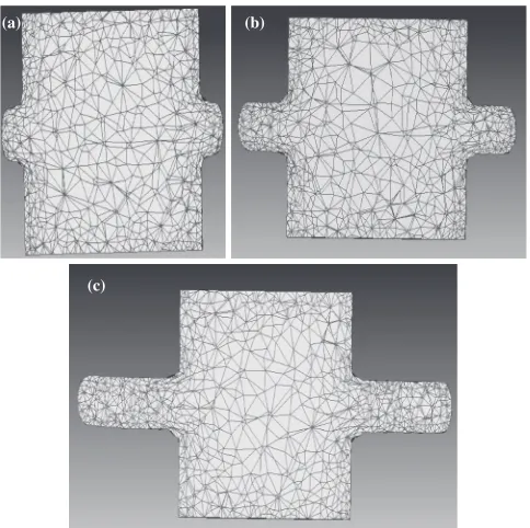
Figure 2 shows the simulated meshes of the deformed billet at different stages. From Fig. 2(a), one can see that there is no dead zone at the initial stage, which can be attributed to the incomplete deformation, as suggested from previous finite-element analysis.14,15)As shown in Figs. 2(b) and 2(c), there remains no dead zone when the meshes are deformed further. The difference is that the meshes are distorted slightly in the upsetting region but largely in the shearing region, as the shapes of the triangle meshes are
(b)
(a)
Upper Die
Billet
Shearing Region Upsetting Region
Lower Die
Forming Region
Plunger
Fig. 1 (a) Schematic plot of dual-directional extrusion (DDE) processing illustrating the configuration of the die and extrusion way, (b) Mesh frame used in the finite-element calculation.
(a) (b)
(c)
[image:2.595.93.503.69.293.2] [image:2.595.306.548.346.587.2]changed severely due to the shearing stress. In addition, the arcs of the meshes at the shearing stage turn wide, suggesting that textures of the inside grains are almost parallel to the shear plane at the die corner. Further, this implies non-uniformity presents in microstructures of the billet. Evident-ly, many tiny yet homogeneous triangles are present in the forming region, which agree with the deformation experi-ments showing that the grains are refined largely during the deformation. Moreover, we also note that the meshes for the billets in direct contact to the die walls suffer somewhat severer deformation than those at the center of die, in consistence with the possible large deformation force there.
3.2 Distribution of effective strain and stress
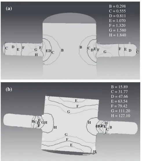
The distributions of strain and stress for the deformed billet are shown in Fig. 3, where one can see that they vary noticeably with the deformation regions. As seen in Fig. 3(a), the effective strain increases rapidly as the sample slides along the channel due to the drastic shearing, and exhibits a value of 1.58 in the forming region. The strain reaches its maximum (1.84) at the edge of product but returns to its original state after the bearing land. This indicates that strain in the shearing region is larger than that in other regions and can hence provide more energy, which is important for triggering the grain subdivision and dynamic recrystalliza-tion there. In passing, it is noteworthy that unlike the report that a strain as high as 34 can be obtained by the ECAE with at least three passes,16) the maximum effective strain (1.84) induced by our one-pass DDE seems to be smaller. Nevertheless, we have noticed that our maximum effective strain is still considerably larger than that of 0.865 in the sample deformed once by the ECAE.17)Further increase of
our effective strain remains in progress. Figure 3(b) shows the distribution of effective stress from upsetting to forming region. Like what was seen in the strain case, the stress also increases from the upsetting to shearing region, and ulti-mately has a maximum value of 127.1 MPa in the shearing region. However, when the billet flows across the forming region, the stress relaxes rapidly and finally reduces to a minimum (15.89 MPa), which is ascribed to a co-effect of the absence of shearing and the presence of extrusion-ratio deformation.
3.3 Microstructure
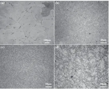
The optical micrographs for the alloys before and after the DDE processing are shown in Fig. 4. From this figure, the average grain size for the as-casted sample is estimated to be about 300mm, while those for the samples extruded at 573, 623, and 673 K to be 3, 7, and 12mm, respectively. It should be noted that the grain size as small as 3mm can also be obtained in the solid recycled specimen and virgin extruded specimen.18)However, there appears significant difference in processing conditions between ours and those in the above reference, for example, extrusion ratio of44 : 1, processing temperature of 503 K, and original grain size of 52mmin the report. In comparison, our extrusion ratio (10.125) is much smaller, temperature (573 K) is higher, and our original grain size (300mm) is much larger. Evidently, this demonstrates that the DDE is effective in refining grains of Mg-based alloys, and that the extrusion temperature is important in tuning the microstructures of the AZ31 alloys. Apart from these two methods, the ECAE can also refine the grains significantly, but, in general, requires multi passes, for example, to 3.7mmafter three passes and 3.0mmafter five passes.19,20)Moreover, we note that our average grain size of 3mmdeformed at 573 K is much smaller than those of 8.1 and 10.5mmextruded once by the ECAE at 593 K and 493 K,19,21) respectively, and even much less than that of 17mmafter two-pass ECAE at 473 K.22) This improved grain refinement is mainly attributed to the fact that in addition to having the vertical corner in the ECAE method, the DDE technique also introduces the flexible extrusion ratio processing, which can technically result in even severer plastic deformation. From Figs. 4(b) and 4(c), one can see that the grains are almost equiaxed and homogeneously distributed after the DDE, a manifestation of the occurrence of dynamic recrystallization. The recrystallization may account for the larger grains in Mg alloys in comparison with the pure Al and Al-based alloys.22–24)
To further shed light on the mechanism of grain refine-ment, we performed TEM observations on the microstructure evolution during the DDE. From Fig. 5, we note again that the dynamic recrystallization takes place during the extru-sion, and that the shearing and forming can affect the microstructure significantly. As marked in Fig. 5(a), a large number of heterogeneously distributed dislocations appear, in particular, inside the coarse grains in the upsetting stage. Clearly, the tangled dislocations pile up at the grain boundaries (Fig. 5(b)), and arrange themselves to form cell structures and walls (Fig. 5(c)), which can be attributed to the severe plastic strain imposed by the intersection of die channels. This is in agreement with the simulated large stress B = 0.298
C = 0.555 (a)
D = 0.811 E = 1.070 F = 1.320 G = 1.580 H = 1.840
C D E F G
H F
ED C B B CD E F G F E D C
(b) B = 15.89C = 31.77
D = 47.66 E = 63.54 F = 79.42 G = 111.20 H = 127.10 G E F H G CD B F E H HGFED H E F G H F HGFE CB
[image:3.595.47.292.478.757.2]and strain induced in the shearing region. Further, these dislocation walls are arranged so as to form new grains, that is, they ultimately evolve into boundaries of the new grains (marked by arrows in Fig. 5(d)). In addition, a number of dislocations are also observed in the sub-grain interiors, which are subsequently evolved into sub-grains and thus in-crease the grain-boundary energy drastically.25)Such grains with nonequilibrium boundaries could store sufficient energy to induce dynamic recrystallization during deformation.
From Fig. 5, one can also notice that grains are further refined and the low angle grain boundaries (LAGBs) become more pronounced during the DDE, which confirm again the presence of grain subdivision and dynamic recrystallization. The presence of LAGBs can also be seen in Fig. 6(a) showing that a large fraction of boundaries has a small misorientation angle in the upsetting-shearing region. To reveal the structure of the sample at the final stage, we present in Fig. 5(e) a TEM image for the sample in the forming region. From this figure, very few dislocations can be observed in the recrystallized grain interiors, demonstrating that the dynamic recrystallization takes place sufficiently. A careful analysis of the image as well as the EBSD data reveals that most of the grain boundaries turn out to be either the high-angle grain boundaries (HAGB) (see also Fig. 6(b)) or the well defined sub-grain boundaries. However, the grain size is reduced to 13mm, which is a direct consequence of the recrystallization and generation of HAGB after the rearrangement of dislocations.26)
Further investigation on the distribution of misorientation angle (Fig. 6) shows that the average misorientation
fre-quency below 15 becomes dominant in the upsetting-shearing region, which implies the appearance of grain subdivision and transformation of tangled dislocations into sub-structures. Further deformation with a ratio of 10.125 reduces the number of LAGBs noticeably due to the increase of strain, although it remains larger than that at the upsetting stage. On the other hand, the deformation can increase the number of HAGBs, as a large fraction of boundary has a misorientation angle of 30 (Fig. 6(b)). It is worth mention-ing that the formation of LAGB at the initial stage of deformation and its late transformation into HAGB during the deformation are not exclusive in our DDE processed Mg alloys but a typical consequence of continuous dynamic recrystallization in the wrought Mg alloys.27,28)Nevertheless, this structural optimization may affect or improve the poor mechanical properties of Mg alloy AZ31 significantly.
4. Conclusion
We propose a new dual-directional extrusion technique and apply it to the important engineering Mg alloy AZ31, aimed at investigating the evolution of its microstructure and mechanical property with different deformation stages. We find that a homogeneously fine microstructure with mean grain size of 3mmcan be obtained by deforming the sample once at 573 K using the DDE technique, which is attributable to the strain-localization-induced dynamic re-crystallization. In addition, the shearing deformation and extrusion-ratio deformation are found to be crucial to trigger the dynamic recrystallization during the DDE processing.
(a)
(b)
(d)
(c)
100µµm 20µm
50µm 50µm
[image:4.595.114.483.71.373.2]Using several microscopic techniques, we find that the high density of tangled dislocations pile up at grain boundaries, arrange themselves so as to form cell structures and walls, and eventually evolve into low and high angle grain boundaries.
Acknowledgments
This work is supported in part by the National 973 Major Project of China, ‘‘The Key Fundamental Problem of Processing and Preparation for High Performance Magne-sium Alloy’’, under Grant No. 2007CB613700, and by a Grant-in-Aid for Young Scientists (B) (Grant No. 22760500) and the IKETANI Science and Technology Foundation (Grant No. 0221047-A).
2 4 6
(a) Upsetting-Shearing Region
4 6
Fr
equency (%) (b) Forming Region
0
0 80
0 2
Misorientation Angle, Degree/° 60 40
20
Fig. 6 Misorientation distribution of the AZ31 alloys in (a) between the upsetting and shearing region and (b) the forming region during the DDE at 573 K. The angle is measured from 3.
(b)
400nm
(a)
400nm
(c)
Cell Structures
200nm
b
(d)
a
400nm
(e)
B
New Grains
400nm
A
[image:5.595.110.486.72.540.2] [image:5.595.65.277.615.748.2]REFERENCES
1) T. J. Luo, Y. S. Yang, W. H. Tong, Q. Q. Duan and X. G. Dong: Mater. Design31(2010) 1617–1621.
2) S. Muhammad and W. Lothar: Mater. Sci. Eng. A506(2009) 141–147. 3) T. Murai, S. Matsuoka, S. Miyamoto and O. Yoshinari: J. Mater. Proc.
Tech.141(2003) 207–212.
4) Y. Prasad and K. P. Rao: Mater. Design30(2009) 3723–3730. 5) X. M. Feng and T. T. Ai: Trans. Nonferrous Met. Soc. China19(2009)
293–298.
6) T. Mohri, M. Mabuchi, M. Nakamura, T. Asahina, H. Iwasaki, T. Aizawa and K. Higashi: Mater. Sci. Eng. A290(2000) 139–144. 7) W. J. Kim, C. W. An, Y. S. Kim and S. I. Hong: Scr. Mater.47(2002)
39–44.
8) S. H. Hsiang and J. L. Kuo: J. Mater. Proc. Tech.140(2003) 6–12. 9) K. Xia, J. T. Wang, X. Wu and M. Gurvan: Mater. Sci. Eng. A410–411
(2005) 324–327.
10) M. Janecˇek, M. Popv, M. G. Krieger, R. J. Hellmig and Y. Estrin: Mater. Sci. Eng. A462(2007) 116–120.
11) S. Il-Heon, L. Jeong-Ho and I. Yong-Taek: J. Mater. Proc. Tech.171
(2006) 480–487.
12) Y. Yi-Lang and L. Shyong: J. Mater. Proc. Tech.140(2003) 583–587. 13) P. B. Pragnell, C. Harris and S. M. Roberts: Scr. Mater.37(1997)
983–989.
14) G. Palumbo, D. Sorgente and L. Tricarico: Mater. Design31(2010)
1308–1316.
15) A. V. Nagasekhar and Y. Tick-Hon: Comput. Mater. Sci.30(2004) 489–495.
16) Y. Iwahashi, Z. Horita, M. Nemoto and T. G. Langdon: Acta Mater.46
(1998) 3317–3331.
17) S. W. Chung, H. Somekawa, T. Kinoshita, W. J. Kim and K. Higashi: Scr. Mater.50(2004) 1079–1083.
18) Y. Chino, R. Kishihara, K. Shimojima, H. Hosokawa, Y. Yamada, C. Wen, H. Iwasaki and M. Mabuchi: Mater. Trans.43(2002) 2437–2442. 19) C. W. Su, L. Lu and M. O. Lai: Mater. Sci. Tech.23(2007) 290–296. 20) S. H. Kang, Y. S. Lee and J. H. Lee: J. Mater. Proc. Tech.201(2008)
436–440.
21) H. K. Kim and W. J. Kim: Mater. Sci. Eng. A385(2004) 300–308. 22) A. Yamashita, Z. Horita and T. G. Langdon: Mater. Sci. Eng. A300
(2001) 142–147.
23) J. M. Garcı´a, S. Swaminathan, C. M. Cepeda-Jime´nez, T. R. McNelley, O. A. Ruano and F. Carren˜o: J. Alloy. Compd.478(2009) 139–143. 24) Z. Horita, T. Fujinami, M. Nemoto and T. G. Langdon: Metall. Mater.
Trans. A31(2000) 691–702.
25) L. Jin, L. D. Liang, M. D. Li, Z. X. Qing, C. H. Bin and D. W. Jiang: Mater. Sci. Eng. A423(2006) 247–252.
26) T. M. Liu, J. Z. Liu, L. W. Lu, Y. Liu and Z. C. Wang: Mater. Trans.50
(2009) 765–770.
27) J. C. Tan and M. J. Tan: Mater. Sci. Eng. A339(2003) 124–132. 28) H. Watanabe, H. Tsutsui, T. Mukai, K. Ishikawa, Y. Okanda, M. Kohzu