VOIC
E MAIL ADMIN
IS
TRA
T
OR F
E
A
T
URE
S
T
O RE CO RD A B R O A DC AS T MESSAG E — C all th e vo ice mai l extensi on num ber . — P ress, then enter the system ad
mi nistrator m ailbo x nu mb er and pass-word. — P ress , then pres s . — R
ecord your message.
— W hen yo u h ave co mpl eted you r message, han g u p OR pr ess fo r mo re opt ion s.
T
O PE RFOR M MAILBOX MAI N T E NA NC E:
— C all th e vo ice mai l extensi on num ber . — P ress, then enter the system ad
mi nistrator m ailbo x nu mb er and pass-word. — P ress , then pres s . — D ial the m ai lbo x, ex tensio n ID , or gro up l ist num ber to be programm ed. Program th e p ersonal o pti ons, foll owi ng the prom pts, as usual.
T
O IM P O R T A FA X DO CU ME NT:
— U sing a fax machine, call the voice ma il extens ion. — P ress and th en enter th e sy st em adm ini strat or m ailb ox num ber an d pass-word. — P ress , then pres s . — Enter the fax
document number . If th e do cument nu mber d oes n ot alr eady exist, press i f the num ber is correct OR press
and re-renter the
number . If th e docu m ent num ber al re ad y exi st s, Pre ss to replace the document OR press to enter another number . If the docum ent i s bein g sent , u pda ted, or d eleted,
that number cannot be
used ri ght no w . Ent er a ne w num ber or hang up . If yo u di d no t ent er a valid number , enter a new number . — W hen p rom pted , press ST AR T on yo ur fax m achi ne. — W hen th e fax transm issi on is co mpl ete, press to co ntin ue i m po rt ing do c-um ents, o r press to exit.
Q
UI
CK
R
EFERENCE
G
UIDE
T
O
S
YSTEM
AND
V
OICE
M
AIL
A
DMINISTRATOR
F
EATURES
These are the
basic
instructions f
or the most frequ
ently used system adminis
tor an d vo ice mail admin istrator features . For detailed info rm ation on these tu res, r efer to th e Administrator ’s Guide .
SY
STE
M
ADMINIS
TRA
T
OR FEA
T
URE
S
T
O PLA C E TH E SYS TEM IN NI GH T OR DA Y MODE:
— W hile on-hoo k, en ter.
T
O PLA C E A SIN G LE NO DE IN DA Y OR NIG H T MODE:
— W hile on-hoo k, enter(Enabl e Net w ork N ight Mode) enter
(
Enable Netwo rk Day Mode).Then enter the desired
no de num ber .
T
O SET SY STE M OR NE TWO R K DA TE AN D TIME:
— W hile on-hook , enter( Syst em D ate/T im e) OR enter
(
Netw ork Dat e/T im e). — U se the dial pad but ton s to ent er the m onth , day , and year . (For press 010 300 fo r Jan uary 3 , 2000 .) OR pres s to skip ahe ad without chan ging th e date. — U se the dialp ad b utt ons t o en ter thetime in hours and mi
nu tes. (For pl e, en ter 0900 fo r 9 :00 .) OR press twi ce to ex it with out chang ti me. — If th e syst em is set f
or 12-hour display format,
press for AM or pre for PM.
T
O SYN CH RO N IZE NE T W ORK TIME:
Wh ile on-hoo k, en ter.
T
O RE SPO ND TO AN AL A R M MESSAG E:
— W hena minor alarm indication appear
s, wr it e d ow n th e alarm information. — W hile o n-h
ook, clear the
al arm by en tering
(
Clear Sys Alarm) OR en teri ng(
Clear Network Alarm). — L ook up t he alarm i n th e Adm ini strat or ’s Gui de and t ake th e appropriate action. 9 1 # 9 2 9 4 # 3 # 3 # 9 8 6 0 9 8 6 1 9 8 6 2 9 8 0 0 1 0 # # 1 9 8 1 1 9 8 5 0 9 8 5 1 Pa rt No. ©I nt er-T el, Inc. Jun e 2003 pr int ed in UST
O PR OGRA M S YST EM SP EED-DIA L NU MBE R S
:
— W hi le on-hook , ent er. — E
nter the spee
d-dial lo cat ion cod e (000 -99 9). — T o chang e or pr ogra m the name: En ter the desi red n ame for the speed -dial number: In n um eric mo de, the
dialpad buttons are used
to en ter n umb ers 0-9, t he bu tton is used fo r entering a hyphen, a nd the bu tton is used fo r entering a colon. In alphan umeric mode, di alpad b uttons are used to enter the d esired let ters, nu mb ers, and p unct uat ion . Th e num ber of tim es a bu tto n is p ressed d eter-min es whic h ch ara ct er is en tere d. Whe n ad join ing c har ac ter s a re loc at ed un
der the sam
e b utt on , p ress to ad
vance to the next character
. R efer to th e fo ll owin g chart to p rog ram in for m atio n i n alph anu m er ic mod e. ( N ot e that le tters correspo nd to th e le tters print ed on the di alpad bu tto ns.) T o erase the curr en t
name and leave
it blank: Pres s repeatedly until the name is
erased. Then press
. T o leave th e na me th e sa m e: Pr ess . — E nter th e nu m ber (u p to 48 di git s) to be stored. —P re ss .
*The character available depe
nd s on the soft ware versi on. NUMBER O F TIMES BUTT ON IS PRESSED BU TT ON 1 2 3 4 5 6 7 8 9 10 11 ENGLISH C HARAC TERS KA TA K ANA CH ARAC TERS 1 -& ( ) 1 A I U E O a 2 AB C ' 2 KA KI KU KE KO i 3 DEF ! 3 SA SHI SU SE SO u 4 GH I * 4 TA CHI TSU TE TO e 5 JK L # or / * 5 NA NI NU NE NO o 6 MN O Ñ o r # * 6 HA HI FU HE HO ts u 7 PQ R S 7 MA MI MU ME MO ya 8 TU V ? 8 YA YU YO . , yu 9 WX Y Z 9 RA RI RU RE RO yo 0 @: . , 0 WA WO N pa ba long 9 8 0 1 # FWD MU TE # # #
Issue 8.0, June 2003
©Inter-Tel, Inc. June 2003 printed in US
ADMINISTRATOR’S GUIDE
This Inter-Tel® Axxess® Administrator’s Guide is released by INTER-TEL, INC. as a guide for system
and voice mail administrators. It provides information necessary to properly administer the system. The contents of this guide, which reflect current INTER-TEL standards, are subject to revision or change without notice. Some features or applications mentioned may require a future release and are not avail-able in the initial release. Future product features and applications are subject to availability and cost. Some features or applications may require additional hardware and/or specific software. Software pack-ages released after the publication of this guide will be documented in addenda to the guide or succeed-ing issues of the guide.
For additional information, please contact you local INTER-TEL service representative.
For sales, service, or technical support,
contact your local authorized Inter-Tel dealer.
If you have any questions or comments regarding this manual or
other technical documentation, contact
Inter-Tel’s Technical Publications Department at:
[email protected]
All products and services mentioned in this publication are the trademarks, service marks, registered marks, or registered service marks of their respective owners.
Inter-Tel® is a registered trademark of Inter-Tel, Incorporated.
Axxess®, Executone®, and Inside Track® are registered trademarks of Inter-Tel, Incorporated.
IBM® and OS/2® Warp are registered trademarks of International Business Machines Corporation.
MS-DOS® and Microsoft® Windows® are registered trademarks of Microsoft Corporation.
Page v
CONTENTS
PAGE
FCC Regulations . . . viii
Safety Regulations. . . xi
Introduction
1
Introduction . . . 2
Telephone System. . . 2
Voice Processor . . . 4
Administrator Procedures
7
Introduction . . . 8
System Administrator Features . . . 8
Programming and Using DSS/BLF Buttons . . . 37
Voice Mail Administrator Features . . . 40
System Hardware
65
Introduction . . . 66
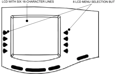
Station Instruments . . . 67
Optional System Equipment . . . 92
System Features
95
Introduction . . . 100
Access to the Features . . . 100
Attendant Stations . . . 113
Hunt Groups. . . 115
Trunk Features . . . 132
Inter-Tel Phone Features . . . 147
Multilingual Capability . . . 155
Intercom Calls . . . 159
Inter-Station Messages . . . 165
Off-Hook Voice Announce (OHVA) . . . 170
Outside Calls . . . 172
Placing Calls On Hold . . . 181
Page vi
CONTENTS
PAGE
Call Waiting . . . 184
Call Transfer . . . 186
Call Screening . . . 189
Reverse Transfer . . . 190
Conference Calls . . . 191
Record-A-Call . . . 196
Agent Help . . . 198
System Forwarding . . . 201
Call Forwarding . . . 208
Speed Dialing . . . 213
Intercom, Speed-Dial, and Feature Code Directory . . . 221
House Phone . . . 224
Redialing . . . 226
Redirect Call . . . 228
Paging . . . 229
Remove from Paging . . . 230
Do-Not-Disturb . . . 230
Do-Not-Disturb Override . . . 234
Remote Feature Programming . . . 235
Default Station . . . 239
Hookflash . . . 240
Reminder Messages . . . 241
Record Keeping and Maintenance Features . . . 243
Voice Processing Features
251
Introduction . . . 253
Automated Attendant . . . 254
Call Routing Announcement . . . 258
Fax-On-Demand . . . 261
Directories . . . 263
Record-A-Call . . . 266
Scheduled Time-Based Application Routing (STAR) . . . 267
SMDR Information Storage and Retrieval . . . 268
Page vii
CONTENTS
PAGE
Using Voice Mail . . . 276
Unified Messaging . . . 288
Automatic Fax Detection . . . 292
Index
293
Default Feature Codes
305
Page viii
FCC Regulations
Important
1. This equipment complies with Part 68 of FCC rules. On the side of the equipment cabi-net is a label that contains, among other information, the FCC registration number and ringer equivalence number (REN) for this equipment. Customers connecting this equip-ment to the telephone network shall, before such connection is made, give notice to the telephone company of the particular line(s) to which such connection is to be made, and shall provide the telephone company with the following information:
— Complies with Part 68 of FCC rules
— FCC registration number: BE2USA-64572-MF-E (for MF-rated systems), BE2USA- 64573-KF-E (for KF-rated systems), or BE2USA-24359-PF-E (for PBX systems)
— USOC numbers of required interface jacks (see chart on next page) — Service order code (SOC), as applicable (see chart on next page) — Facility interface code (FIC) (see chart on next page)
— Ringer equivalence number (REN), as applicable (see chart on next page)
NOTE: The REN is used to determine the quantity of devices which may be con-nected to the telephone line. Excessive RENs on the telephone line may result in the devices not ringing in response to an incoming call. In most, but not all areas, the sum of the RENs should not exceed five (5.0). To be certain of the number of devices that may be connected to the line, as determined by the total RENs, contact the telephone company to determine the maximum REN for the calling area.
The telephone company should also be given notice upon final disconnection of this equipment from the particular line(s).
It is also the responsibility of the customer to provide the telephone company with reg-istration numbers of any other devices which are configured for connection to the tele-phone network.
2. This equipment cannot be used on public coin service provided by the telephone com-pany. Connection to party line service is subject to state tariffs. (Contact the state public utility commission, public service commission, or corporation commission for informa-tion.)
3. If this equipment causes harm to the telephone network, the telephone company will notify the customer in advance that service may be temporarily discontinued. But if advance notice is not practical, the telephone company will notify the customer as soon as possible. Also, the customer will be advised of the right to file a complaint with the FCC, if necessary.
4. The telephone company may make changes in its facilities, equipment, operations, or procedures which may affect the operation of this equipment. If so, the customer shall be given advance notice so that any necessary modifications can be made in order to maintain uninterrupted service.
Page ix 5. If trouble is experienced with this equipment, contact a local authorized factory service representative for repairs and/or warranty information. The customer, users, and unau-thorized technicians should not repair, make adjustments to, or attempt to service this equipment in any way.
6. In the event of trouble with the telephone line(s), this equipment must be disconnected from the telephone line(s). If trouble ceases, the equipment must be repaired by an authorized factory service representative. If the trouble continues to occur with the equipment disconnected, the telephone company should be notified that they have a problem. If this is the case, repairs or adjustments made by the telephone company will be made at their expense.
7. Allowing this equipment to be operated in such a manner as to not provide proper answer supervision signaling is in violation of Part 68 of FCC rules. This equipment returns answer supervision signals to the public telephone network when: answered by the called station, answered by the attendant, routed to a recorded announcement that can be administered by the equipment user, and routed to a dial prompt. This equipment also returns answer supervision on all DID calls forwarded back to the public telephone network. Permissible exceptions are: a call is unanswered, busy tone is received, and reorder tone is received.
8. This equipment is capable of providing users access to interstate providers of operator services through the use of equal access codes. Failure to provide equal access capabili-ties is a violation of the Telephone Operator Consumer Services Improvement Act of 1990 and Part 68 of the FCC Rules.
TYPE OF PORT INTERFACE
FACILITY INTERFACE CODE (FIC)
RINGER EQUIV ALENCE NO. (REN)
SERVICE ORDER CODE (SOC) USOC JACK CONNECTOR 2-Wire Loop 02LS2 0.6B
–
RJ21X 2-Wire Loop/Ground 02LS2/02GS2 3.6B/4.4B–
RJ21X 2-Wire Ground 02GS2 0.6B–
RJ21X OPX Class C* 0L13C–
9.0F RJ11C, RJ21X2-Wire DID** 02RV2-T 0.0B AS.2 RJ11C, RJ21X
D4 Superframe/AMI 04DU9-BN
–
6.0Y RJ48CD4 Superframe with
B8ZS 04DU9-DN
–
6.0Y RJ48CExtended
Superframe (ESF) 04DU9-1KN
–
6.0Y RJ48CESF with B8ZS 04DU9-1SN
–
6.0Y RJ48CPrimary Rate ISDN 04DU9-1SN
–
6.0Y RJ48C* Also interfaces with Class A and B.
** When using T1 facilities to provide DID service, do not use the DID facility interface code (FIC); instead, pro-vide the telephone company with DID answer supervision code “AS.2” and the FIC for the requested T1 service.
Page x
Notice
This equipment generates and uses radio frequency energy and if not installed and used prop-erly, that is, in strict accordance with the manufacturer’s instructions, may cause interference to radio and television reception. It has been type tested and found to comply with the limits for a Class A computing device in accordance with the specifications in Subpart J of Part 15 of FCC Rule. Operation of this equipment in a residential area may cause unacceptable interference to radio and TV reception requiring the operator to take whatever steps are necessary to correct the interference. However, there is no guarantee that interference will not occur in a particular installation. If this equipment does cause interference to radio or television reception, which can be determined by turning the equipment off and on, the user is encouraged to try to correct the interference by one or more of the following measures:
•
Reorient the receiving antenna•
Relocate the equipment cabinet with respect to the receiver•
Check that the equipment cabinet and receiver are not on the same circuit; the equip-ment cabinet must be powered from an isolated, dedicated AC outletIf necessary, the user should consult the dealer or an experienced radio/television technician for additional suggestions. The user may find the following booklet prepared by the FCC help-ful: “How to Identify and Resolve Radio-TV Interference Problems”
This booklet is available from the U.S. Government Printing Office, Washington, D.C. 20402, Stock No. 004-000-00398-5.
If RFI problems persist, contact Inter-Tel Customer Support.
The Axxess® system is now product safety certified by Canadian Standards Association (CSA)
for use in both the United States and Canada.
CAUTION
THE TELEPHONE INSTRUMENTS SPECIFICALLY DESIGNED FOR THIS SYSTEM HAVE HEARING-AID COMPATIBLE HANDSETS THAT ARE IN COMPLIANCE WITH SECTION 68.316 OF THE FCC RULES.
THE IP SLA COMPLIES WITH UL1950/CSA950 AND EN 60950 STANDARDS AND COMPLIES WITH EN 55022 AND PART 15 OF FCC RULES.
Page xi
Safety Regulations
Important Safety Instructions
The following safety information is reprinted from UL 1459. When using your telephone equipment, basic safety precautions should always be followed to reduce the risk of fire, elec-tric shock, and injury to persons, including the following:
1. Read and understand all instructions.
2. Follow all warnings and instructions marked on the product.
3. Unplug this product from the wall outlet before cleaning. Do not use liquid cleaners or aerosol cleaners. Use a damp cloth for cleaning.
4. Do not use this product near water (for example, in a wet basement).
5. Do not place this product on an unstable cart, stand, or table. The product may fall, causing serious damage to the product.
6. Slots and openings in the cabinet and the back or bottom are provided for ventilation, to protect it from overheating; these openings must not be blocked or covered. This prod-uct should never be placed near or over a radiator or heat register. This prodprod-uct should not be placed in a built-in installation unless proper ventilation is provided.
7. This product should be operated only from the type of power source indicated in the manual. If you are not sure of the type of power source to your building, consult your dealer or local power company.
8. This product is equipped with a three-wire grounding type plug, a plug having a third (grounding) pin. This plug will only fit into a grounding type power outlet. This is a safety feature. If you are unable to insert the plug into the outlet, contact your electri-cian to replace your obsolete outlet. Do not defeat the safety purpose of the grounding type plug.
9. Do not allow anything to rest on the power cord. Do not locate this product where the cord will be abused by persons walking on it.
10. Do not use an extension cord with this product’s AC power cord. The AC outlet for this product should not be used for any other electrical equipment.
11. Never push objects of any kind into this product through cabinet slots as they may touch dangerous voltage points or short out parts that could result in a risk of fire or electric shock. Never spill liquid of any kind on the product.
CAUTION
The “NRTL/C” indicator adjacent to the CSA mark on the product label signifies that the Axxess® system has been evaluated to the applicable ANSI/UL and CSA Standards for use
in both the United States and Canada. NRTL (Nationally Recognized Testing Laboratory) is a designation granted by the U.S. Occupational Health and Safety Administration (OSHA) to laboratories which have been accredited to certify products to U.S. Standards. Before installation, also check the local electrical codes for important information concern-ing the installation of telephone and electronic equipment.
Page xii
12. To reduce the risk of electric shock, do not disassemble this product, but take it to a qualified serviceman when some service or repair work is required. Opening or remov-ing covers may expose you to dangerous voltages or other risks. Incorrect reassembly can cause electric shock when the product is subsequently used.
13. Unplug this product from the wall outlet and refer servicing to qualified service person-nel under the following conditions:
a. When the power supply cord or plug is damaged or frayed. b. If liquid has been spilled into the product.
c. If the product has been exposed to rain or water.
d. If the product does not operate normally by following the operating instructions. Adjust only those controls that are covered by the operating instructions because improper adjustment of other controls may result in damage and will often require extensive work by a qualified technician to restore the product to normal operation. e. If the product has been dropped or the cabinet has been damaged.
f. If the product exhibits a distinct change in performance.
14. Avoid using a telephone (other than a cordless type) during an electrical storm. There may be a remote risk of electric shock from lightning.
15. Do not use the telephone to report a gas leak in the vicinity of the leak.
Save These Instructions
CAUTIONThis exclamation point within a triangle (which, for example, is silk-screened on the front of the system cabinet) is intended to alert the user to the presence of important operating and maintenance (servicing) instructions in the litera-ture accompanying the product. Be sure to read and follow all of the instruc-tions included in this manual.
Page 1
Introduction
CONTENTS
PAGE
Introduction . . . 2
Telephone System. . . 2
Networking . . . 2
System Administrator Duties . . . 3
Voice Processor . . . 4
Voice Mail Networks . . . 5
Page 2 Introduction
INTRODUCTION
This Administrator’s Guide provides all of the information an administrator should need to know about the system hardware and features, and it gives detailed instructions on their use. Refer to the user guide provided with each phone for simplified instructions on using telephone and voice mail system features.
TELEPHONE SYSTEM
The Inter-Tel® Axxess® Telephone system is a state-of-the-art, digital, voice/data, hybrid tele-phone system. As a hybrid system, it incorporates many of the user-friendly features of key systems with many of the expanded features and flexibility of private branch exchange (PBX) systems.
The system is designed to meet the needs of growing businesses. In fact, the system’s unique digital signal processing (DSP) structure allows it to be easily adapted and expanded as busi-ness communication needs change, especially with the Caller ID, Automatic Number Identifi-cation (ANI), Dialed Number IdentifiIdentifi-cation Service (DNIS), and Integrated Services Digital Network (ISDN) features. The modular design makes the system easy to install and service. And, the programmable features provide an abundance of user-friendly applications to meet each customer’s needs. Highlights of the system’s design include:
•
Advanced microprocessor technology.•
Modular, easily replaceable hardware with add-on capabilities for optional features.•
Flexible programming to customize many system and station features.NETWORKING
With system software versions 5.0 and later, you can connect two or more phone systems to form a network that provides a seamless interface between the systems. To the user, the net-work appears as though it is one integrated system. With few exceptions, the user can perform all of the functions across the network that he can within a single phone system.
In this manual, all references to a “network” mean two or more connected systems. Each sys-tem in a network is called a “node.”
The maximum capacities for networking are listed in the following table.
* The maximum number of stations and trunks that can be installed is limited by the number of voice channels and/or system memory resources available.
FEATURE/DEVICES CAPACITY
System Nodes per network 63
Local devices per node 1792*
Off-node devices per node 8000
Page 3
System Administrator Duties
SYSTEM ADMINISTRATOR DUTIES
As a system administrator, you can provide the following services:
•
Place the local phone system or other systems in the network in night or day mode•
Set the date and time of the local system•
Set the network date and time and re-synchronize clocks in the network.•
Make database changes (see page 11 for a list of programming areas)•
Program system speed-dial numbers on the local system•
Receive and clear displayed system and network alarms•
Use diagnostic mode features to:— Freeze and unfreeze database history on the local system or other systems in the network
— Print error logs
— Seize specific devices for troubleshooting purposes Administrator features are described in detail beginning on page 8.
Any Inter-Tel phone can be designated as an administrator station through Database Program-ming. All designated administrator stations should be equipped with display phones to show system alarms and make programming easier.
Page 4 Voice Processor
VOICE PROCESSOR
The system Voice Processor can be used for any of the following applications:
•
Voice Mail: This application handles all calls that are directed to voice mail (other than through the Message Notification/Retrieval application) by subscribers and non-sub-scribers. Callers will hear the main company greeting, followed by a menu of available options. Stations can forward or transfer calls directly to their mailbox.•
Message Notification/Retrieval: The Message Notification/Retrieval application pro-vides voice mail message notification and quick mailbox access.•
Directory Services: Directory services provide callers with a list of mailboxes and extension IDs.•
Automated Attendant: The automated attendant is a programmable feature that can be used to provide automated call answering service. Calls can transfer, forward, or directly ring in to an automated attendant. When an automated attendant answers a call, it plays a recording that gives dialing instructions. After hearing the recording (or at any time while it is playing), the caller may then dial an extension or mailbox number.•
Automated Attendant Recall Destination: If a call, that is transferred by the auto-mated attendant, is not answered before the Transfer Voice Processor timer expires, the call recalls the Automated Attendant Recall Destination. The Recall Destination announces that the station is unavailable and allows the caller to leave a message (if the station has an associated mailbox) or dial another extension.•
Call Routing Announcement: Call Routing Announcements can be used two ways: — A Call Routing Announcement application can be used in place of a playbackdevice. The playback device function is especially useful for programming hunt group announcement and overflow stations. When called, the Call Routing Announcement application will play a recording and then hang up.
— The Call Routing Announcement application can use Digit Translation which allows the caller to press a single digit for access to a mailbox, a fax-on-demand function, or a station or hunt group that has an associated mailbox or extension ID. Digit translation can be programmed for each digit 0-9, #, and *, plus a Timeout that is used when the caller does not enter a digit. Each digit can lead to a “digit translation node” that has its own digit translation values. This layered Call Rout-ing Announcement digit translation creates a “tree” of programmable digit transla-tion nodes.
Page 5
Voice Mail Networks
•
Record-A-Call: This feature allows a station user to record an ongoing call in a voice mailbox message. When a station user enters the Record-A-Call feature code, the sys-tem places a call to the station’s assigned Record-A-Call application. When the applica-tion answers, the system sets up a conference call with the staapplica-tion’s Record-A-Call mailbox. If programmed, the mailbox plays a greeting to indicate that the recording is in progress.•
STAR: The Scheduled Time-Based Application Routing (STAR) enhances the pro-grammability of the voice mail application greetings. With STAR, applications can be programmed to play alternative greetings for holidays and weekends. A STAR applica-tion is a table of up to 20 entries, that serves as a “routing table” which tells the Voice Processor which application will be used, based on day and time information in the table. (The applications are programmed to play the greetings, not the STAR applica-tion. The STAR routes the call to the right applicaapplica-tion.)•
Station Message Detail Recording (SMDR) Information Storage: SMDR informa-tion can be stored on the Voice Processor’s hard disk and then processed using call record sorting software, such as Inter-Tel’s Inside Track®.VOICE MAIL NETWORKS
A Voice Processor can be installed on any or all nodes in the system network. These Voice Pro-cessors can also be networked together to allow a caller to leave a message on the local Voice Processor for a mailbox located on another Voice Processor in the network.
The maximum capacities of the network are listed in the following table.
a This is the maximum number of nodes supported by the software. System traffic may limit
the actual number of nodes that can be supported without affecting system performance.
b This is the maximum number of mailboxes supported by the NT-based software.
FEATURE/DEVICES CAPACITY
Voice Processors per network 100a
Local or Off-Node Mailboxes and/or Extension IDs per
Voice Processor node 10,000
b
System Audio Interface Ports per node 40
Applications per node 150
Group Lists per node Members per group list
1000 1500 Remote Message Notification Numbers per mailbox 18
Audiotex Recordings per node 500
Message Notification/Retrieval Applications per node 1
System Passwords per node 4
Page 6 Voice Mail Administrator Duties
VOICE MAIL ADMINISTRATOR DUTIES
As the voice mail administrator, you can use special features that are not provided to other voice mail users. The system administrator mailbox has all standard subscriber features plus the ability to do the following:
•
Record a broadcast message•
Perform mailbox and group list maintenance•
Create and select custom audiotex recordings (voice mail company greetings, auto attendant recordings, call routing announcements, and hunt group overflow and announcement station recordings)•
Import fax documents•
Customize voice mail promptsPage 7
Administrator Procedures
CONTENTS
PAGE
Introduction . . . 8
System Administrator Features . . . 8
Placing the System in Night Mode. . . 9
Placing Nodes in Day or Night Mode . . . 9
Setting System Date and Time . . . 9
Setting Network Date and Time . . . 10
Synchronize Network Time . . . 11
Database Programming . . . 11
Station Programming Using an Administrator’s Station. . . 13
System Programming Using an Administrator’s Station . . . 17
Trunk Programming Using an Administrator’s Station . . . 23
System and Network Alarm Reporting . . . 32
System Alarms . . . 32
Network Alarms . . . 32
Freezing/Unfreezing the System History . . . 34
Freezing/Unfreezing the Network History . . . 34
Seizing a Device . . . 35
Enabling/Disabling The Call Processing Card Modem . . . 36
Assigning the CPC Modem to a DSS/BLF Button . . . 37
Programming and Using DSS/BLF Buttons . . . 37
Voice Mail Administrator Features . . . 40
Broadcast Messages . . . 40
Mailbox/Group List Maintenance . . . 41
Importing Fax Documents . . . 42
Custom Audiotex Recordings. . . 43
Customized Voice Mail Prompts . . . 45
Page 8 Introduction
INTRODUCTION
During database programming, any Inter-Tel phone can be designated as a system administra-tor and/or a voice mail administraadministra-tor. All administraadministra-tor stations should be equipped with dis-play phones to show system alarms and to make programming easier.
This section gives you all of the instructions for using the Administrator Features of the system and voice mail.
•
System Administrator Features begin below.•
Voice Mail Administrator Features begin on page 40.A quick reference card is located in the front of this book for your convenience.
Refer to the System Features and Voice Processing Features chapters for detailed descriptions of the system and Voice Processor and for general user procedures.
NOTE: The telephone system provides a choice between American English, British English, Spanish and Japanese prompts and displays. As an administrator, you must know which lan-guage is considered Primary and which is Secondary for the system.
SYSTEM ADMINISTRATOR FEATURES
Any display Inter-Tel phone (attendant or non-attendant) can be assigned as a telephone system administrator. System administrator stations provide the following services:
•
Place the local node or other nodes in the network in night or day mode•
Set the date and time of the local node•
Set the network date and time and re-synchronize clocks in the network•
Make database changes (see page 11 for a list of programming areas)•
Enable, disable, and reset local and off-node Call Processing Card modems•
Program system speed-dial numbers on the local node•
Receive and clear displayed system and network alarms•
Use diagnostic mode features:— Freeze and unfreeze the database history for the local node or any node in the net-work using programmed freeze zones
— Print error logs
— Seize specific devices for troubleshooting purposes
Any Inter-Tel phone station can be programmed to be an administrator station by the database programmer or by another administrator station.
NOTE: Single-line sets can not be used as an administrator station.
If a non-administrator station user attempts to use the administrator features, the user will hear reorder tones, and the display will show CANNOT ACCESS RESERVED FEATURE.
Page 9
Placing the System in Night Mode
PLACING THE SYSTEM IN NIGHT MODE
An administrator station can place the local node in day or night mode. The day/night mode determines which lists the system will use for trunk access, toll restriction, etc.
Night mode also affects the night transfer relays on the Options Card (OPC). The relays are activated when the system is placed in night mode. See SPECIFICATIONS in the Installation Manual for details.
TOTURNNIGHTMODEONOROFF:
While on hook, enter the Night Ring On/Off feature code (9860). You hear a single confirmation tone.The display shows NIGHT MODE IS ON (or OFF). Then, if night mode was turned on, the display shows THE SYSTEM IS IN NIGHT MODE until day mode is turned on.
PLACING NODES IN DAY OR NIGHT MODE
An administrator station can place one or more nodes in day or night mode. The day/night mode determines which lists the system will use for trunk access, toll restriction, etc.
The network determines the day/night mode status of a call based on the day/night mode status of the node where the trunk resides.
TOTURNNIGHTMODEON:
1. While on hook, enter the Enable Network Night feature code (9861). 2. You are prompted to enter a node number. Enter the desired node number.
3. You hear a single confirmation tone.The display shows NIGHT MODE IS ON. Then the display shows NODE X IS IN NIGHT MODE until day mode is turned on.
TOTURNDAYMODEON:
1. While on hook, enter the Enable Network Day feature code (9862). 2. You are prompted to enter a node number. Enter the desired node number. 3. You hear a single confirmation tone.The display shows DAY MODE IS ON.
SETTING SYSTEM DATE AND TIME
Occasionally, the system time or date needs to be reset (for example, when the system is defaulted or for daylight-saving time). Any administrator can change the date and time that appears on all display phones and in the SMDR reports. The day of the week is automatically calculated and set by the system when the date is entered.
TOSETTHESYSTEMDATEANDTIME:
NOTE: If you make a mistake, press to backspace or press or CANCEL to leave it unchanged and start over.
1. While on hook, enter the Set Date/Time feature code (9800). Your display shows DATE
(current date).
If you do not need to change the date, press or ACCEPT to skip to the TIME XX:XX prompt.
2. Use the dialpad buttons to enter the month, day, and year. For example, press 020301 for February 3, 2001. When finished, the display shows TIME (current time). If you entered the date incorrectly, the display shows INVALID DATE, and you are prompted to enter a new date.
MUTE
Page 10 Placing the System in Night Mode NOTE: If using a station programmed for Japanese, enter the date as year, month, date. For example, 010203 for February 3, 2001.
If you do not need to change the time, press or ACCEPT twice to exit. The display shows SYSTEM DATE AND TIME UPDATED.
3. Use the dialpad buttons to enter the time in hours and minutes. (For example, enter 0900 for 9:00.) If you entered the time incorrectly, the display shows INVALID TIME and you are prompted to enter a new time.
4. If the system is set for 12-hour display format, the display shows SELECT AM OR PM (AM=1 PM=2). Press (or the AM menu button) for AM or press (or the PM
menu button) for PM. The display shows SYSTEM DATE AND TIME UPDATED. If you press any button other than 1 or 2, the display shows INVALID TIME and you are prompted to enter a new time.
NOTE: If using a station programmed for Japanese, the prompts will be reversed and you will set the AM/PM before the hour and minutes.
SETTING NETWORK DATE AND TIME
Occasionally, the network time or date needs to be reset (for example, when the system is defaulted or for daylight-saving time). Any administrator can change the date and time that appears on all display phones and in the SMDR reports in the network. The day of the week is automatically calculated and set by the system when the date is entered.
TOSETTHENETWORKDATEANDTIME:
NOTE: If you make a mistake, press to backspace or press or CANCEL to leave it unchanged and start over.
1. While on hook, enter the Set Network Date and Time feature code (9810). Your display shows DATE (current date).
If you do not need to change the date, press or ACCEPT to skip to the TIME XX:XX prompt.
2. Use the dialpad buttons to enter the month, day, and year. For example, press 020301 for February 3, 2001. When finished, the display shows TIME (current time).
NOTE: If using a station programmed for Japanese, enter the date as year, month, date. For example, 010203 for February 3, 2001.
If you entered the date incorrectly, the display shows INVALID DATE, and you are prompted to enter a new date.
If you do not need to change the time, press or ACCEPT twice to exit. The display shows SYSTEM DATE AND TIME UPDATED.
3. Use the dialpad buttons to enter the time in hours and minutes. (For example, enter 0900 for 9:00.)
NOTE: If using a station programmed for Japanese, the prompts will be reversed and you will set the AM/PM before the hour and minutes.
If you entered the time incorrectly, the display shows INVALID TIME, and you are prompted to enter a new time.
#
1 2
MUTE
#
Page 11
Placing the System in Night Mode
4. If the node is set for 12-hour display format, the display shows SELECT AM OR PM (AM=1 PM=2). Press (or the AM menu button) for AM or press (or the PM
menu button) for PM. The display shows SYSTEM DATE AND TIME UPDATED. If you press any button other than 1 or 2, the display shows INVALID TIME, and you are prompted to enter a new time.
SYNCHRONIZE NETWORK TIME
Administrators can synchronize the minutes past the hour across the network without changing the hour. This is useful when the nodes are in different time zones.
NOTE: If a node's time is off by more than 30 minutes, synchronizing the minutes may cause the hour to change. Also, network time is automatically synchronized every day at 12:30 AM (00:30), using the time setting on the node with the lowest number.
An administrator can synchronize the clocks in all nodes in the network using the following procedure.
TOSYNCHRONIZENETWORKTIME:
While on hook, enter the Synchronize Network Time feature code (9811). You hear a confirmation tone, and the display shows NETWORK TIME SYNCHRONIZED.
DATABASE PROGRAMMING
Any administrator station can perform database programming using an Inter-Tel phone. How-ever, it requires a display phone, and an Executive Display, Professional Display or Model 8560 Phone is strongly recommended.
NOTE: If using an analog phone, the administrator will need to use the PREVIOUS/NEXT or UP/DOWN buttons in place of the Volume button in the instructions in this section.
The database areas that can be programmed by an administrator station include the following:
Station Programming:
•
Create or delete Administrator stations•
Create or delete Attendant stations•
Create or delete House Phones•
Assign stations to Attendants•
Program usernames•
Program station toll restrictionSystem Option Programming:
•
Program Do-Not-Disturb (DND) messages•
Program up to ten passwords for the Database Programming feature•
Program station extensions•
Swap extensionsTrunk Programming:
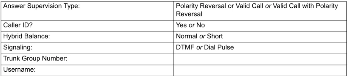
•
Individual trunk answer supervision type, caller information, hybrid balance, signaling type (DTMF or pulse), and trunk group assignment•
Trunk group answer access, ring-in, toll restrictions, and trunk listsPage 12 Placing the System in Night Mode
Entry to the Database Programming feature at the administrator station can be protected using a password. A password would prevent unauthorized users from altering the system database.
NOTE: Passwords are very important to system security. Without sufficient password protec-tion, the telephone system database is vulnerable to unauthorized access.
Depending on the database changes made by the administrator, the system may require a reset after programming. If so, the system will prompt the administrator for a reset and ask if it should be done immediately or delayed. Delaying the reset would prevent interruption in ser-vice. However, if a reset is required it should be done as soon as possible to permit proper sys-tem operation.
NOTE: A system reset will drop all calls in progress. Entering Alphanumeric Information:
When entering alphanumeric information, such as a username, reminder message, or Do-Not-Disturb message, press or USE ALPHA MODE/USE NUMERIC MODE menu but-ton to switch back and forth between alphanumeric and numeric mode.
•
In numeric mode, the dialpad buttons are used to enter numbers 0-9, the pound ( ) button is used for entering a hyphen (-), and the asterisk ( ) button is used for entering a colon (:). For example, 1 00 would enter “1:00” in numeric mode.•
In alphanumeric mode, dialpad buttons are used to enter the desired letters, numbers, and punctuation. The number of times a button is pressed determines which character is entered. For example, 533266 would enter “JEAN” in English. When adjoining charac-ters are located under the same button, press to advance to the next character. For example, 66 6667776 would enter “NORM.” Refer to the chart below to program information in alphanumeric mode. (Note that letters correspond to the letters printed on the dialpad buttons.) The Japanese characters will be available only if the Multilingual Support premium feature is included in your software license, Japanese is programmed as a Primary or Secondary Language, and the administrator’s station is set for Japanese.*The character available depends on the software version.
**The Japanese characters are only available if the Multilingual feature is enabled and Japanese is installed as the secondary language.
MSG
#
FWD FWD
NUMBER OF TIMES BUTTON IS PRESSED
BUTTON 1 2 3 4 5 6 7 8 9 10 11
ENGLISH/SPANISH CHARACTERS KATAKANA CHARACTERS**
1 - & ( ) 1 A I U E O a 2 A B C ’ 2 KA KI KU KE KO i 3 D E F ! 3 SA SHI SU SE SO u 4 G H I * 4 TA CHI TSU TE TO e 5 J K L # or /* 5 NA NI NU NE NO o 6 M N O Ñ or #* 6 HA HI FU HE HO tsu 7 P Q R S 7 MA MI MU ME MO ya 8 T U V ? 8 YA YU YO . , yu 9 W X Y Z 9 RA RI RU RE RO yo 0 @ : . , 0 WA WO N pa ba long
Page 13
Placing the System in Night Mode
Station Programming Using an Administrator’s Station
You can use your administrator station to program the following station information:
•
Create or delete Administrator stations: You can program any other Inter-Tel phone to be an additional administrator station, or you can delete administrators. (You cannot program this for your own station or a single-line station.)•
Create or delete Attendant stations: You can program any station to be an Attendant station, or you can delete Attendants.•
Create or delete House Phones: You can program any station to be a House Phone, or you can delete House Phones.•
Assign stations to Attendants: You can change the assigned Attendant for each sta-tion.•
Program usernames: You can program or change the username for any station.•
Program station toll restrictions: You can program toll restriction classes of service for the stations. Station toll restrictions are described in detail on page 137.The Station Database Programming process is summarized in the flowchart shown on page 16. See page 59 for a Program Planning Sheet.
NOTE: If necessary, you can press the asterisk ( ) or Speaker button to cancel programming and discard any unsaved changes, at any time during the following procedure.
TOPROGRAMSTATIONS:
1. While on hook, enter the Program Database feature code (9932).
2. If a password is required, the display shows ENTER PASSWORD. Use the dialpad to enter your 1-8 digit password and press . (If you enter an incorrect password or do not press , the display shows INVALID PASSWORD.)
If a password is not required, skip this step.
3. The display shows ENTER DATABASE OPTION. (Display phones also show the options: STATION, SYSTEM, and TRUNK.)Press or the STATION menu button. 4. The display shows ENTER STATION EXTENSION. Enter the extension number of the
station to be programmed using one of the following methods. (If you enter an invalid extension number, you hear reorder tones and must try again.)
Enter a complete number:Enter the extension number using your dialpad. When the circuit information is displayed, press again to continue.
Enter a partial number: Enter a partial extension number, then press , the high end of the Volume button, or the ACCEPT menu button. The display shows the exten-sion number, username and circuit number of the station that most closely matches the partial extension number. Press or ACCEPT to program the displayed station, or scroll to another station as described below.
Scroll through the numbers:To scroll through the extension number list, press the high end of the Volume button or NEXT to scroll forward, or press the low end of the Volume button or PREVIOUS to scroll backward. When the desired extension number is displayed, press or ACCEPT to continue.
# # 1 # # # #
Page 14 Placing the System in Night Mode
5. The display shows ENTER STATION OPTION. Select one of the following:
a. Station Flags: This option allows you to set the Administrator Station, Attendant, and House Phone flags. To select it, press or the STATION FLAGS menu but-ton. There are three flags that can be programmed: Administrator, Attendant, and House Phone. (However, you cannot program the Administrator flag for your own station or for a single-line station.) To program the flags, do the following:
1. To scroll to the desired flag: Press the high end of the Volume button or
NEXT to scroll forward, or press the low end of the Volume button or
PRE-VIOUS to scroll backward.
2. To enable or disable a displayed flag: Press or the ON menu button to enable the flag. Or, press or the OFF menu button to disable the flag. 3. To save your programming when all flags are set correctly: Press or
ACCEPT to save the new flag settings. The display shows DATABASE
UPDATED and then returns to the ENTER STATION OPTION prompt. 4. To exit without saving your changes: Press or CANCEL to exit. The
dis-play shows NO UPDATE PERFORMED and then returns to the ENTER STATION OPTION prompt.
b. Station Information:This option allows you to select an attendant for the station or program the station’s username. To select it, press or the STATION INFO
menu button. The display shows ENTER STATION INFO OPTION. Select one of the following:
1. Attendant: To assign an attendant to serve this station, press or the
ATTENDANT menu button. The display shows ENTER ATTENDANT
EXTENSION. Enter the desired extension number. When the circuit informa-tion is displayed, press again to return to the ENTER STATION INFO OPTION prompt. The display shows DATABASE UPDATED. (Or, to cancel your entry, press or CANCEL. The display shows NO UPDATE PER-FORMED.)
2. Username: To change the username of the station, press or the USER-NAME menu button. The display shows ENTER USERNAME. Enter the new name as described on page 12. (Or, to cancel your entry, press or CAN-CEL. The display shows NO UPDATE PERFORMED.)
1 1 2 # 2 1 # 2
Page 15
Placing the System in Night Mode
c. Toll Restriction: This option allows you to set the station class of service for day and/or night modes. To select it, press or the TOLL RESTRICTION menu but-ton. Then do the following:
1. The display shows TOLL RESTRICTION OPTION. Press or the COS DAY menu button to program day mode toll restriction. Or, press or the
COS NIGHT menu button to program night mode toll restriction.
2. The display shows SET DAY (or NIGHT) COS XX. If this is not the COS you wish to program, scroll to the correct COS by pressing the high end of the Volume button or NEXT to scroll forward, or press the low end of the Volume button or PREVIOUS to scroll backward. The default COS numbers are as follows. See page 137.
COS 01 – ARS Only COS 02 – Deny Area/Office COS 03 – Deny Operator COS 04 – Deny Toll Access COS 05 – Deny International COS 06 – Deny Equal Access COS 07 – Deny Local Calls COS 08 – Denied Numbers COS 09 – Allowed Numbers
3. When the correct COS is displayed, press or the ON menu button to enable the toll restriction. Or, press or the OFF menu button to disable it. 4. If desired, repeat steps c2 and c3 to program additional COS toll restrictions. 5. Press or ACCEPT to save the COS programming. The display shows
DATABASE UPDATED and then returns to the TOLL RESTRICTION OPTION prompt.
6. Press again to exit to the ENTER STATION OPTION prompt.
6. When the display shows ENTER STATION OPTION, press again to exit to the ENTER STATION EXTENSION prompt. You can then program another station by repeating these steps or press or ACCEPT once more to exit to the ENTER DATA-BASE OPTION prompt.
7. When finished with all programming, press while the ENTER DATABASE OPTION prompt is displayed. This ends the programming session.
8. If a system reset is required, the display shows ENTER SYS RESET OPTION. Do one of the following:
— Delayed Reset: Press or the DELAYED menu button to delay the reset. The display shows DELAYED RESET SCHEDULED. The system will be reset at the pre-programmed time.
— Immediate Reset: Press or the IMMEDIATE menu button to reset the system now.
NOTE: A system reset will drop all calls in progress. 3 1 2 1 2 # # # # # 1 2
Page 16 Station Database Programming Flowchart
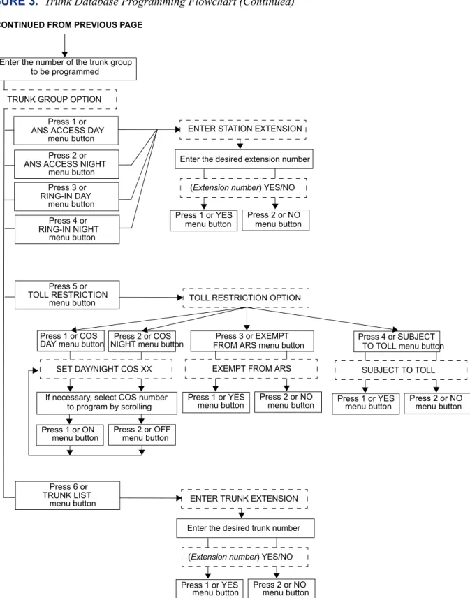
FIGURE 1.
Station Database Programming Flowchart
Enter Program Database feature code 9932
Press 1 or STATION menu button
ENTER DATABASE OPTION
ENTER STATION EXTENSION
Enter desired station extension number, then #
ENTER STATION OPTION
Press 2 or STATION INFO menu button
STATION INFO OPTION
Press 3 or TOLL RESTRICTION menu button
TOLL RESTRICTION OPTION Press 1 or STATION FLAGS
menu button
Select flag to program
Press 1 or ATTENDANT menu button Press 2 or USERNAME menu button Enter new username extension Enter Attendant’s Press 1 or ON menu button to enable Press 2 or OFF menu button
to disable
Press 1 or COS DAY menu button
for day mode
Press 2 or COS NIGHT menu button
for night mode
SET DAY/NIGHT COS XX
If necessary, select COS number
Press 1 or ON menu button to enable COS
If desired, select another COS number to program by scrolling
Press 2 or OFF menu button
to disable COS
to program by scrolling
YOUR INPUT PHONE DISPLAYS
AT ANY LEVEL:
Press * or the Speaker button to cancel any unsaved changes and back up to exit pro-gramming.
Press # or ACCEPT to save changes and back up one display level.
INFORMATION IN THIS CHART IS SHOWN AS FOLLOWS:
Page 17
Station Database Programming Flowchart
System Programming Using an Administrator’s Station
You can use your administrator station to program the following system-wide information:
•
Define Do-Not-Disturb messages: The messages for the Do-Not-Disturb feature can be reprogrammed through an administrator’s station. (See page 230 for information concerning their use.) Administrators can delete or change messages 01-20 to any value (up to 16 characters). When the system has a programmed Primary and Secondary Lan-guage, the system has default Do-Not-Disturb messages in both languages. (Available languages are American English, British English, Spanish, and Japanese.) The current language of the programming phone determines which list is programmed. (See page 155 for a description of the Change Language feature.) The Secondary Language translation has the same meaning as the Primary Language message. The default mes-sages are:When two languages are enabled and DND messages are changed, the programmer should attempt to keep the meanings for the messages in both lists the same. That is, if the Primary Language message 02 is changed to “PAGE ME,” a similar message should be programmed for the Secondary Language message 02.
•
Select an administrator Database Programming password: Entry to the Database Programming feature at the administrator stations can be protected using a password. A password would prevent unauthorized users from altering the system database.•
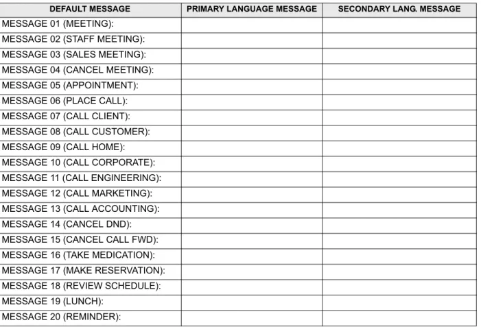
Define reminder messages: System reminder messages can be changed using an administrator’s station. (See page 241 for information about using reminder messages.) The messages can have up to 16 characters each. When Primary and Secondary Lan-guages are enabled, the system has default reminder messages in both lanLan-guages. The current language of the programming phone determines which list is programmed. (See page 155 for a description of the Change Language feature.) Each Secondary Language translation has the same meaning as the Primary Language message. The default mes-sages are:01 DO-NOT-DISTURB 11 OUT OF TOWN 'TIL 02 LEAVE A MESSAGE 12 OUT OF OFFICE 03 IN MEETING UNTIL 13 OUT UNTIL 04 IN MEETING 14 WITH A CLIENT 05 ON VACATION 'TIL 15 WITH A GUEST 06 ON VACATION 16 UNAVAILABLE 07 CALL ME AT 17 IN CONFERENCE 08 AT THE DOCTOR 18 AWAY FROM DESK 09 ON A TRIP 19 GONE HOME 10 ON BREAK 20 OUT TO LUNCH
01 MEETING 11 CALL ENGINEERING 02 STAFF MEETING 12 CALL MARKETING 03 SALES MEETING 13 CALL ACCOUNTING 04 CANCEL MEETING 14 CANCEL DND 05 APPOINTMENT 15 CANCEL CALL FWD 06 PLACE CALL 16 TAKE MEDICATION 07 CALL CLIENT 17 MAKE RESERVATION 08 CALL CUSTOMER 18 REVIEW SCHEDULE 09 CALL HOME 19 LUNCH
Page 18 Station Database Programming Flowchart
When two languages are enabled and reminder messages are changed, the programmer should attempt to keep the meanings for the messages in both lists the same. That is, if the Primary Language message 02 is changed to “GO TO AIRPORT,” a similar mes-sage should be programmed for the Secondary Language mesmes-sage 02.
•
Program new extension numbers for stations: The extension number for any station can be changed by an administrator. The new extension number cannot conflict with an existing number.•
Swap extensions: An extension number can be relocated (swapped) to another station. To swap extensions, the two affected stations must meet the following criteria:— Both devices must reside on the same node as the administrator performing the swap.
— Both devices must be the same type (i.e., both digital phones or both single-line sets).
— Neither device can be the administrator phone performing the swap.
The System-Wide Database Programming process is summarized in the flowchart shown on page 22. See page 59 for a Program Planning Sheet.
If necessary, you can press or the Speaker button to cancel programming and discard any unsaved changes, at any time during the following procedure.
TOPROGRAMTHESYSTEMDATABASE:
NOTE: If you wish to change the Japanese DND or reminder message sets, make sure your station is set in Japanese mode. See page 155 for an explanation of the Change Language fea-ture.
1. While on hook, enter the Program Database feature code (9932).
2. If a password is required, the display shows ENTER PASSWORD. Use the dialpad to enter your 1-8 digit password and press . (If you enter an incorrect password, the dis-play shows INVALID PASSWORD.)
If a password is not required, skip this step.
3. The display shows ENTER DATABASE OPTION. (Display phones show the options: STATION, SYSTEM, and TRUNK.)Press or the SYSTEM menu button.
4. The display shows ENTER SYSTEM OPTION. Select one of the following:
a. Do-Not-Disturb Messages: This option allows you to program the DND messages used by the stations. To select it, press or the DND MESSAGES menu button. Then do the following:
1. The display shows SELECT DND MESSAGE #. Enter a message number or scroll to the desired message. (To scroll to the correct message, press the Vol-ume button or the SCROLL plus NEXT and PREVIOUS menu buttons.) 2. When the display shows the desired DND message, enter the new message as
described on page 12.
3. Press or ACCEPT to save the new message. The display shows DATA-BASE UPDATED and then returns to the SELECT DND MESSAGE prompt. (Or, to cancel your entry, press or CANCEL. The display shows NO UPDATE PERFORMED.)
#
2
1
Page 19
Station Database Programming Flowchart
4. To program another message, scroll to the desired message and repeat these steps.
5. Press again to exit to the ENTER SYSTEM OPTION prompt.
b. Password: This option allows you to set a password that limits access to the admin-istrator programming feature. To select it, press or the PASSWORD menu but-ton. Then do the following:
1. The display shows CHANGE PASSWORD TO. Enter a password of up to eight digits, then press . (Or, to erase the password and leave it blank, just press .)
2. The display shows VERIFY PASSWORD. Enter the password exactly as you did in the step above, followed by . The display returns to the ENTER SYSTEM OPTION prompt. (If you hear reorder tones and see an error mes-sage, the passwords did not match and you must start over at the CHANGE PASSWORD prompt.)
c. Reminder Messages: This option allows you to program the reminder messages used by the stations. To select it, press or the REMINDER MSGS menu but-ton. Then do the following:
1. The display shows SELECT REMINDER MSG #. Enter a message number or scroll to the desired message. (To scroll to the correct message, press the Vol-ume button or the SCROLL plus NEXT and PREVIOUS menu buttons.) 2. When the display shows the desired message, enter the new message as
described on page 12.
3. Press or ACCEPT to save the new message. The display shows DATA-BASE UPDATED and then returns to the SELECT REMINDER MSG prompt. (Or, to cancel your entry, press or CANCEL. The display shows NO UPDATE PERFORMED.)
4. To program another message, scroll to the desired message and repeat these steps.
5. Press again to exit to the ENTER SYSTEM OPTION prompt.
d. Station Extensions: This option allows you to assign new extension numbers to sta-tions. To select it, press or the STN EXTENSION menu button.
If programming a station:
1. Press
or
CHANGE EXT. The display shows ENTER STATION EXTEN-SION. Enter the extension number of the station to be programmed using one of the following methods. (If you enter an invalid extension number, you hear reorder tones and must try again.)Enter a complete number:Enter the extension number using your dialpad. When a valid number is entered, the circuit information is displayed. Press again to continue.
Enter a partial number:Enter a partial extension number, then press , the high end of the Volume button, or the ACCEPT menu button. The display shows the extension number, username and circuit number of the station that most closely matches the partial extension number. Press or ACCEPT to program the displayed station, or scroll to another station as described below.
# 2 # # # 3 # # 4 1 # # #
Page 20 Station Database Programming Flowchart
Scroll through the numbers:To scroll through the extension number list, press the high end of the Volume button or the NEXT menu button to scroll forward, or press the low end of the Volume button or the PREVIOUS menu button to scroll backward. When the desired extension number is displayed, press or ACCEPT to continue.
2. The display shows CHANGE X (number) TO EXTENSION. Enter the new extension number for the station. If you enter an invalid number, you hear reorder tones and must try again. If you entered an extension number that is already assigned, the display shows CONFLICTING EXTENSION and you hear reorder tones. When the display returns to ENTER STATION EXTEN-SION, you must start over and select a new extension number.
3. Press or ACCEPT to exit to the ENTER STATION EXTENSION prompt. The display shows UPDATING DATABASE for four seconds and then DATABASE UPDATED. (Or, to cancel your entry, press or CANCEL. The display shows NO UPDATE PERFORMED.)
NOTE: Although the system begins to update the database when you press or ACCEPT, it may take longer than the four-second display to change the extension in the system – especially in a large or busy system.
4. Press or ACCEPT again to exit to the ENTER SYSTEM OPTION prompt. (If an extension number is displayed, press to exit, instead of
or ACCEPT.)
If swapping stations:
1. Press or SWAP EXTS. The display shows ENTER STATION EXTEN-SION. Enter the first extension number to be swapped using one of the fol-lowing methods. (If you enter an invalid extension number, you hear reorder tones and must try again.)
Enter a complete number: Enter the extension number using your dialpad. When a valid number is entered, the circuit information is displayed. Press
or ACCEPT to continue.
Enter a partial number: Enter a partial extension number, then press the button, the high end of the Volume button, or the ACCEPT menu button. The display shows the extension number, user name and circuit number of the sta-tion that most closely matches the partial extension number. Press or
ACCEPT to continue, or scroll to another station as described below.
Scroll through the numbers: To scroll through the extension number list, press the high end of the Volume button or the NEXT menu button to scroll forward, or press the low end of the Volume button or the PREVIOUS menu button to scroll backward. When the desired extension number is displayed, press or ACCEPT to continue.
NOTE: If the feature times out while entering an extension number, the displays shows INCOMPLETE EXTENSION.
2. The display shows SWAP (extension) WITH EXTENSION. Enter the second extension number to be swapped using the same methods previously described. The display shows DATABASE UPDATED.
# # # # # 2 # # # #