Obstacle Avoidance Strategy using Fuzzy Logic
Steering Control of Amphibious Autonomous Vehicle
Khaled Sailan
1,Prof. Dr.-Ing. Klaus-Dieter Kuhnert
2Simon Hardt
3 real time System Institute, Siegen UniversityHölderlinstr. 3, D-57076 Siegen, Germany 1 [email protected]
Abstract
—
A fizzy controller is used to control an obstacle avoidance of Amphibious Autonomous Vehicle. In this classical problem, the aim is to guide an Amphibious Autonomous Vehicle along its path to avoid any static environments containing some static obstacles in front of it. Obstacle avoidance in real-time is a mandatory feature for Amphibious Autonomous Vehicle in a unknown environment.Theadvantages of the fuzzy logic system are that multiple types of input such as that from Laser Scanner Sensor as well as stored map information can be used to guide the.
with the information from the Laser Scanner Sensor like distance and angle ,the Vehicle avoids the obstacle by adjusting the speed of the right and left side through adjusting the hydraulic pump swash plate angle according to the fuzzy logic controller.
A simulation results shows the swash plate angle for left and right side in a different angle and distance situationsKeywords
—
Fuzzy logic , amphibious autonomous vehicle, Robot operating system, laser scanner.I. INTRODUCTION
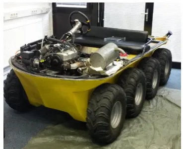
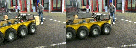
When the Amphibious Autonomous Vehicle shown in figure 1 is moving in unknown and changing environment, the task of the Fuzzy logic system is to guide the robot without colliding with obstacles in the surrounding. For obstacle avoidance is the basic requirement of Autonomous Vehicle navigation, it is a key issue in Amphibious Autonomous Vehicle to design a fast and efficient obstacle avoidance navigation algorithm with the presence of obstacles, which needs to coordinate lots of sensors and actuators to work together. In general, the robot needs to acquire surrounding information via sensors onboard such as laser range finder that can be used to detect obstacles. In the past decades, researchers have exploited many obstacle avoidance navigation algorithms utilizing these sensors. Generally speaking, these methods can be divided into the following categories: model-based method , fuzzy logic method and reactive method based on neural network [1]. Of all the methods, the obstacle avoidance method based on fuzzy logic reacts quickly and is robust to sensor measuring errors, for the robot’s reaction is got from qualitative reasoning of different categories in the fuzzy logic method, so the algorithm proposed in this paper is on the foundation of fuzzy logic principle. Fuzzy logic intelligent obstacle avoidance strategy is addressed in this paper to solve obstacle avoidance problem for Amphibious Autonomous Vehicle tracking a target in unknown environment. Fuzzy obstacle avoidance controller of the strategy is based on fuzzy reactive
control principle to dominate robot’s obstacle avoidance action, and run-to-goal fuzzy controller utilizes fuzzy control to dominate robot’s approaching target action. When the robot is approaching the target with the presence of obstacles, run-to-goal fuzzy controller and fuzzy obstacle avoidance controller compete with each other, therefore, intelligent coordinator is designed to coordinate the two actions mentioned above to generate robot’s ultimate control command. Simulations and experiments validate the effectively and feasibility of the fuzzy intelligent obstacle avoidance control strategy presented in this paper. Many works used fuzzy logic system to mobile robot navigation and representing behaviours [2][3][4].The speed control of the Robot achieved by controlling the hydraulic pump swash plate through controlling the DC Motor position that actuate the pump swash plate for each side where each side has hydraulic pump and hydraulic Motor driven by gasoline engine[5,6].
Figure 1 amphibious autonomous vehicle (DORIS)
II. FUZZY LOGIC
1…Ai 2 are the input fuzzy sets, Bi is the output fuzzy set and y is the output variable. The response of each fuzzy rule is weighted according to the degree of membership of its input conditions. The inference engine provides a set of control actions according to fuzzified inputs. Since the control actions are in fuzzy sense. Hence, a deffuzification method is required to transform fuzzy control actions into a crisp value of the fuzzy logic controller. In fuzzy logic behavior based navigation systems the problem is decomposed into simpler tasks (independent behaviors) . Each behavior is composed of a set of fuzzy logic rule statements aimed at achieving a well defined set of objectives.[8].
Figure 2 The structure of Fuzzy Logic Controller
III. FUZZY LOGIC CONTROLLER DESIGN
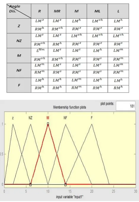
FLC is proposed to move the amphibious autonomous vehicle to its target smoothly. The inputs of FLC are the angle between the robot and the target (error angle), and the distance from the robot to the target. The outputs of FLC are the angular position of the hydraulic pump swash pale which control the hydraulic motor speed . FLC is implemented with seven membership functions for each input as illustrated in figures 3 and 4 this member function is for left Motor and right Motor should be the same [9].
The linguistic variables used for the angle between the robot and the target (angle) are: L: Left, ML: Middle left , M: Middle, MR: Middle right and R: Right. The linguistic variables used for input distance are: Z: Zero, NZ: Near Zero, M: Medium, F: Far and VF: Very Far.
Angle = {R, MR,M, ML, L}
. . . .
Rule 24: IF (angle is ML) AND (distance is F) THEN (Motor_1 is h) and (Motor_2 is h)
Rule 25: IF (angle is L) AND (distance is F) THEN (Motor_1 is h) and (Motor_2 is h)
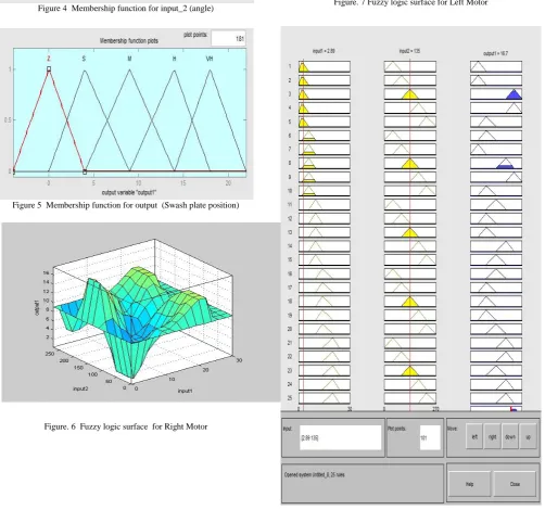
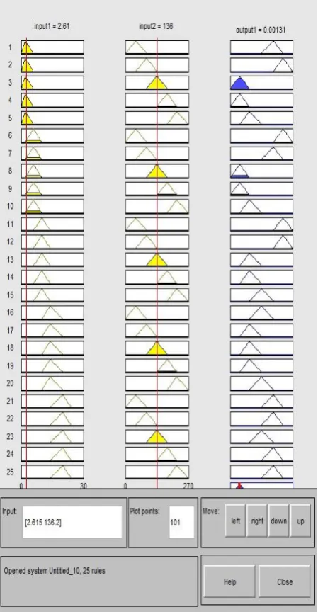
The all fuzzy logic Rules for the left and right Motor illustrates in figure 8 and 9.The relationship between the two inputs and the output shows in figure 6and 7.
TABLE I
Figure 4 Membership function for input_2 (angle)
Figure 5 Membership function for output (Swash plate position)
Figure. 6 Fuzzy logic surface for Right Motor
Figure. 7 Fuzzy logic surface for Left Motor
Figure. 9 Fuzzy logic Rule for Right Motor
IV. STRATEGY OF OBSTACLE DETECTION
It is important to define what an obstacle is before we discuss how an obstacle may be detected. We define an obstacle as something that will cause dangerous or undesirable behavior if hit by the host vehicle (the vehicle on which the obstacle detection system is mounted). Three general classes of obstacles are:
1. people,
2. other vehicles and 3. other roadway obstacles.
The third class of obstacles can include anything from a rock lying in the middle of a mine haul road to the amphibious autonomous vehicle laser scanner at the side of a haul-road. An object should only be considered an obstacle as shown in
Figure. 10 Obstacle detection strategy
V. LASER SCANNER
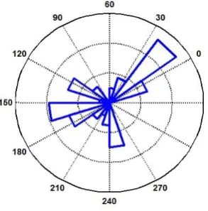
In a Hokuyo UTM-30LX Laser Scanner as in figure 12 Processing section we get the raw data from the laser scanner as shown in figure . Then we cluster the data given by the laser scanner by clustering algorithm. On that basis we get the distance and angle of the obstacles.The laser scanner gives us a field of view showing the complete 270° sweep made by the laser beam as shown in figure 11. The laser beam starts from the right and goes to the left. So at every angle, depending on the resolution set, we can get the distance and position of the objects along the robot’s path. With these values we know exactly at what angle is an obstacle present and what its size is. The fuzzy logic can then decide the path the robot must follow, the angle it must
turn to avoid the obstacle.
Line Track Laser
Scanner
1 2
4 3
e
Figure. 11 Laser scanner pattern
Figure. 12 Hokuyo laser scanner
VI. EXPERIMENTS AND RESULTS
The performance of the fuzzy controller has been tested in real time, under different working conditions. before that the system simulated using Matlab Tools as shown in 13.The simulation results from Matlab/simulink shows the hydraulic pump swash plate angle for hydraulic pump_1(right side) and hydraulic pump_2 (left side) for a different inputs .Figure 14 shows the swash plate angles when the obstacle is in the right side and the distance is near zero the hydraulic pump_2 will close and hydraulic pump_1 will open cause the vehicle to skid away from the obstacle to the left side .Figure 15 shows the swash plate angles for middle left side and the distance is in middle ,the hydraulic pump_1 is in the small angle (small speed ) and hydraulic pump_2 in high speed this will cause the vehicle to skid away to the right side and avoid the obstacle . Figure 16 and figure 17 shows the real swash plate angle for the simulated result discussed above.
Figure 13 Simulation Block diagram of Fuzzy Logic Controller
Figure. 14 Swash plate angle for hydraulic pump 1_2 (Simulation)
Figure. 16 Swash plate angle for hydraulic pump 1_2 (Experiment)
Figure. 17 Swash plate angle for hydraulic pump 1_2 (Experiment)
Figure. 18 Obstacle on the right side (Experiment)
Figure. 19 Obstacle on the left side (Experiment)
Mechatronics and Automation August 5 - 8, Chengdu, China. [2] Sng Hong Lian ,'' Fuzzy Logic Control of an obstacle Avoidance
Robot'', 0-7803-3645-3/96 $5.0001996 IEEE
[3] Mohammed Faisal, Khalid Al-Mutib, Ramdane Hedjar, Hassan Mathkour, Mansour Alsulaiman.'' Multi Modules Fuzzy Logic for Mobile Robots Navigation and Obstacle Avoidance in Unknown
Indoor Dynamic Environment '', Proceedings of the 2013
International Conference on Systems, Control and Informatics [4] Panagiotis G. Zavlangas, Prof. Spyros G. Tzafestas, Dr. K.
Althoefer, ''Fuzzy Obstacle Avoidance and Navigation for Omnidirectional Mobile Robots '', ESIT 2000, 14-15 September 2000,
Aachen, Germany.
[5] Khaled Sailan, Klaus D. Kuhnert, and Hradik Karelia,`` Modeling, Design and Implement of Steering Fuzzy PID Control System for
DORIS Robot``, International Journal of Computer and
Communication Engineering, Vol. 3, No. 1, January 2014.
[6] Khaled Sailan ,DC Motor Angular Position Control using PID Controller for the Purpose of Controlling the Hydraulic Pump, international conference on Control ,Engineering, Information Technology(CEIT´13) proceeding engineering and technology volume 1, pp .22,26 -2013 copyright IPCO
[7] R. L.A. Zadeh, "Fuzzy Sets," Information Control, vol. 8, pp. 338-353, 1965.
[8] Lakhmissi Cherroun, and Mohamed Boumehraz,'' Designing of Goal Seeking and Obstacle Avoidance Behaviors for a Mobile Robot Using Fuzzy Techniques '',J. Automation & Systems Engineering 6-4 (2012): 164-171.
[9] Mohammed Faisal, Ramdane Hedjar, Mansour Al Sulaiman and Khalid Al-Mutib.'' Fuzzy Logic Navigation and Obstacle Avoidance by a Mobile Robot in an Unknown Dynamic Environment '', International
Journal of Advanced Robotic Systems Int J Adv Robotic Sy, 2013, Vol. 10, 37 .2013.
[10] Jonathan Roberts & Peter Corke,'' Obstacle Detection for a Mining Vehicle using a 2D Laser''
http://www.cat.csiro.au/cmst/automation
[11] Mahajan , Ravindra Bhosale , Parag Kulkarni ,'' OBSTACLE DETECTION USING MONO VISION CAMERA AND LASER SCANNER'', IJRET: International Journal of Research in Engineering and Technology eISSN: 2319-1163 | pISSN: 2321-7308.