An Observer-Based Optimal Voltage Control
Scheme for Three-Phase UPS Systems
C. O. Reddy1, Surabhi S Deshmukh2
HOD, Dept. of EE, MSS’s Engineering College, Jalna, Maharashtra, India1
PG Student, Dept. of EE, MSS’s Engineering College, Jalna, Maharashtra, India2
ABSTRACT: This paper proposes a simple optimal voltage control method for three-phase uninterruptible power-supply systems. The proposed voltage controller is composed of a feedback control term and a compensating control term. The former term is designed to make the system errors converge to zero, whereas the latter term is applied to compensate for the system uncertainties. Moreover, the optimal load current observer is used to optimize system cost and reliability. Particularly, the closed-loop stability of an observer-based optimal voltage control law is mathematically proven by showing that the whole states of the augmented observer-based control system errors exponentially converge to zero. Unlike previous algorithms, the proposed method can make a trade off between control input magnitude and tracking error by simply choosing proper performance indexes. The effectiveness of the proposed controller is validated through simulations on MATLAB/Simulink and experiments on a prototype 600-VA test bed with a TMS320LF28335 DSP. Finally, the comparative results for the proposed scheme and the conventional feedback linearization control scheme are presented to demonstrate that the proposed algorithm achieves an excellent performance such as fast transient response, small steady-state error, and low total harmonic distortion under load step change, unbalanced load, and nonlinear load with the parameter variations.
KEYWORDS: Optimal load current observer, optimal voltage control, three-phase inverter, total harmonic distortion
(THD), uninterruptible power supply (UPS).
I.INTRODUCTION
taking into consideration a trade off between control input magnitudes and tracking error unlike previous algorithms. The efficiency of the proposed control method is verified via simulations on MATLAB/Simulink and experiments on a prototype 600-VA UPS inverter tested with a TMS320LF28335 DSP. In this paper, a conventional FLC method in is selected to demonstrate the comparative results because it has a good performance under a nonlinear-load condition, and its circuit model of a three-phase inverter in is similar to our system model. Finally, the results clearly show that the proposed scheme has a good voltage regulation capability such as fast transient behaviour, small steady-state error, and low THD under various load conditions such as load step change, unbalanced load, and nonlinear load in the existence of the parameter variations.
II.SYSTEM MODEL
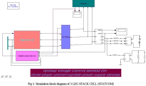
The system considered for simulation is a three-phase balanced source supplying a Diode bridge rectifier feeding a resistive-inductive load, as shown in Fig. 1. This load draws a highly nonlinear current rich in harmonics with a substantial reactive power requirement. A three phase, VSI-based shunt AF is connected to the system for reactive power compensation and harmonics elimination. The simulation is performed in the Simulink/MATLAB environment. Fig. shows the basic simulation model of 3 LEG STACK CELL (STATCOM) This 3 LEG STACK CELL (STATCOM) model is simulated with the above described p–q, SRF based theories. Simulation models for these theories that are inconsistent with the control schemes.
Fig 1: Simulation block diagram of 3 LEG STACK CELL (STATCOM)
III. HARMONIC COMPENSATION
Within the system, active filters can be used to provide suitable harmonic compensation for voltage harmonics and current harmonics. These harmonic are the most important variable requiring compensation.
3.1 Compensation of voltage harmonics: In general, the concern for compensating voltage harmonics is not high due
to the fact that power supplies usually have low impedance. Generally, at the point of common coupling, ridged standards are implemented to ensure a correct level of total harmonic distortion (THD) and voltage regulation is maintained. The problem of compensating for voltage harmonics is to ensure the supply to be purely sinusoidal. This is important for harmonic voltage sensitive devices such as power system protection devices and superconducting magnetic energy storage. Voltage harmonics are related to current harmonics by the impedance of the line. Although compensation of voltage harmonics helps to provide a reduction in current harmonics, this however, does not negate the necessity to current harmonic compensation.
3.2 Compensation of current harmonics: Current harmonic compensation strategies are exceptionally important, current harmonics are greatly reduced by the compensation of voltage harmonics at the consumer’s point of common coupling. The reduction in current harmonics is not only important for reasons such as device heating and reduction in life of devices but also in design of power system equipment. One of the major design criteria covers the magnitude of the current and its waveform. This is to reduce cable and feeder losses. Since the root mean square (RMS) of the load current incorporates the sum of squares of individual harmonics, true current harmonic compensation will aid system designers for better approached power rating equipment.
IV.DSP BASED PULSE GENERATION
To deal with instantaneous voltages and currents in three phase circuits mathematically, it is adequate to express their quantities as the instantaneous space vectors. For simplicity, the three-phase voltages and currents excluding zero-phase sequence components will be considered in the following the DSP TMS320LF28335 DSP model is used for control the current and the voltage in the system this DSP model is used to generate the pulses which is used to required to the statcom which can be produce the stability or the unbalanced system
Probably TMS320LF28335 DSP is designed by the following two theories; 1. Instantaneous Reactive Power (IRP) Theory. 2. Synchronous Rotating Frame (SRF) Theory
These theories are used to generate the reference current and the voltage in the system
Fig 3. Synchronous Rotating Frame (SRF) Theory
V. RESULT AND DISCUSSION
Results according to TMS320LF28335 DSP pulse generator
Fig 4 source voltage and current
Fig .4 shows the source voltage and source current waveforms
Fig 5 shows the load voltage and load current waveforms
Fig 6. THD from source it is 97.75%
FIG: 7 THD from load side it is 2.96%
From Fig 6 and Fig 7, THD from source and load can be noted. It is seen that the THD from source is 97.75% and from load it is 2.96%, hence the THD is reduced
VI.CONCLUSION
REFERENCES
[1] S.B. Bekiarov, A. Emadi, “Uninterruptible power supplies: classification, operation, dynamics, and control,” Applied Power Electronics Conference and Exposition, vol. 1, pp. 597– 604, 2002.
[2] R.A. Gannett, “Control strategies for high power four-Leg voltage source inverters,” M.Sc. Dissertation, Virginia Polytechnic Institute, July 2001.
[3] Motors and generators, NEMA Standards Publication no MG 1-1993.