R E S E A R C H
Open Access
Low complexity look up table based adaptive
digital predistorter with low memory
requirements
R Singla and SK Sharma
*Abstract
With the advent of spectrally efficient wireless communication systems employing modulation schemes with varying amplitude of the communication signal, linearization techniques for nonlinear microwave power amplifiers (PAs) have gained significant interest. In this article, a low complexity, direct-learning multilevel lookup table based adaptive digital predistortion technique has been proposed to linearize a PA. A loop delay compensation scheme has been used to achieve a significant reduction in convergence time and an improvement in linearization accuracy in the presence of an unknown loop delay. Compared with the conventional predistorters, the proposed technique shows fast adaptation speed which enables the predistorter to track time-varying PA nonlinearities.
1. Introduction
Power amplifiers (PAs) are important components in a communication system, but they are inherently non-linear. The nonlinearity produces spectral re-growth, which leads to adjacent channel interference and viola-tions of the out of band emission standards. It also causes in band distortion, which degrades the bit error rate and data throughput of the communication system. To reduce the nonlinearity, the PA can be backed off so that it operates within the linear portion of its operating region. However, newer transmission formats, such as wideband code division multiple access, have large fluc-tuations in their signal envelopes, i.e., high peak-to-aver-age power ratios. This means that the PA needs to be backed off well below its maximum saturated output power in order to handle infrequent peaks, which result in very low efficiencies.
To maintain linearity and efficiency, one can apply linearization to the PA through several compensation techniques such as feedback, feed-forward, and digital predistortion (DPD). In feedback approach, part of the output power is fed back to control the input power. But, this method demands a high loop gain and a suffi-cient phase margin for stability [1-3]. On the other
hand in feed-forward compensation, a suitable signal is added to the output signal for linearization. But in case of high power PAs a high power summing point can hardly be implemented. In DPD technique, the PA input signal is predistorted in such a manner that the overall system becomes approximately linear, as depicted in Figure 1.
DPD works entirely in the digital domain and is already in use in 2G systems. The techniques are mostly based on look up tables (LUTs) [4], using a memory-less characteristic of the PA. With large signal bandwidths as in 3G systems, memory effects become more pronounced [5]. Therefore, for such systems memory-less LUT approach will be of no use. Some of the noted work on LUT-based DPD can also be found in [6-8]. In this article, attention is focused on the development of an adaptive LUT-based DPD lineariza-tion technique which solve the linearizalineariza-tion problem in an optimal way.
In the following sections, an adaptive DPD technique is modeled and simulated. The aim of this article is to develop a linearization technique which is less complex and requires less memory from FPGA implementation point of view.
In Section 2, the basic approach is described. In the last section, the simulation of the system and the com-putation of the LUT values have been reported.
* Correspondence: [email protected]
Electronics and Communication Engineering Department, Thapar University, Patiala, India
2. Basic approach used in design of adaptive digital predistorter
LUT-based digital predistorters have low computational complexity, but they require significantly more memory space to store the model parameters than polynomial-based digital predistorters. Thus, LUT-polynomial-based digital pre-distorters have slow convergence speed as compared to polynomial-based digital predistorters. Comparatively, evaluation of a polynomial function is more computa-tionally complex than a simple memory LUT entry and compensation of higher orders of nonlinearity and memory effects requires a high order polynomial. For newer spectral efficiency transmission formats, a predis-torter bandwidth of several tens of MHz might be required for implementation of these high order polyno-mials. In this article, a novel low complexity LUT-based adaptive digital predistorter with reduced memory requirements has been proposed by using interpolation and efficient spacing of table entries, which leads to low LUT requirement. The proposed adaptive digital predis-torter has much higher convergence rate as compared to other LUT-based adaptive digital predistorters.
In the proposed design, polar LUT-based predistorter [9] has been used and is shown in Figure 2.
Functions fr(x) and fθ(x) denote the nonlinear
AM-AM and AM-AM-PM distortions of PA. The polar predistor-ter consists of two LUTs that approximate the inverse
function of the PA’s amplitude distortion
hρ(x) =fρ−1(x) and the phase compensation function hθ(x) = -fθ(x).
For computing the error in determining hr(x) and
hθ(x), consider the nth entry of the amplitude LUT. For
input amplitude, xi=xn+εx with 0 <εx≤dn, wheredn= xn+1-xn is the width of the nth interval, the output of
the LUT predistorter will behr(xi)+εhr. Because the
cal-culation in error of hr(x) andhθ(x) is similar. So, only
derivation for calculating the errorεhrin determininghr
(x) will be presented, and is as follows:
Lethr(x) be a doubly differentiable function that is
evaluated at points (xi, yi) withyi =hr(xi), where iÎ
1,2,...,,N. The closed-form expression of the interpola-tion error within the interval [xn, xn+1] will be derived,
for 1 <n<N. Let us assume that the interval considered is small enough thathr(x) can be approximated by a
sec-ond-order polynomial within thenth interval. This is
equivalent to neglecting the error terms above the sec-ond-order term in a Taylor series expansion. Conse-quently, the second-order derivative of hr(x) can be
DPD PA Cascaded
+
=
Figure 1Cascade of digital predistorter and PA.
considered as a constant within the interval. The pre-vious assumption is reasonable here since otherwise a lin-ear approximation offin that interval would yield a very inaccurate approximation.hr(x) is therefore given by
hρ(x) =αx2+βx+γ for xn≤x≤xn+1 (1) After a few trivial algebraic manipulations, the coeffi-cients a, bandgcan be calculated from the two refer-ence points as functions of hρ(x),xn,xn+1,yi,yn+1
The linear approximation of hr(x) in the nth interval
can be formulated as follows
˜
hρ(x) =ax+b (5)
whereaandb can also be expressed as a function of xn, xi+1,yn, yn+1.
xn<x<xn+1can be calculated as follows
ei(x) =hρ(x)− ˜hρ(x) (8) width of thenth interval
εx=x−xn (10)
and
dn=xn+1−xn (11)
The expression of the linear interpolation error can then be rewritten as follows
εhρ=hρ(x)εx
(εx−dn)
2 (12)
The amplitude at the output of the PA is
xo=fρ[hρ(xi) +εhρ]
Also the amplitude error measured at the PA’s output can be expressed aser=xo-xi
The output phase error can be expressed as
eθ =fρ(xi)εx
(εx−dn)
2 (15)
Assuming that the amplitude and phase errors to be very small, the output of the PA can be written as
vo= (xi+ex)ej(θi+eθ)
Thus the error at the output of the PA can be given by
eo=vo−vi
≈exejθi+eθxiej(θi+π/2)
(17)
The residual error at the output of the PA consists of two terms resulting from the approximation errors in the amplitude and phase LUTs. These two error terms can be considered independent of each other to simplify the remaining calculations. The total noise contribution
of the nth entry to the output SNR can be computed
using the usual quantizer assumption [10] that εx is a random variable uniformly distributed in [0, dn]. The mean-squared error (MSE) contribution of thenth entry of the amplitude table is
E|eρ|2= hρ
Similarly, the contribution of the nth of the phase
E|eθ |2≈ hθ (x
n)2
120 xn
2
dn4 (19)
For an arbitrary LUT spacing achieved using a com-pander [10]c(x), the LUT entry width is related to the compander by
dn≈
1
Nc(xn)
, (20)
where N is the LUT size and V is the maximum
amplitude addressable by the LUT. For the special case
of uniform spacing c(x) = x anddn= 1/Nis constant.
Assuming that the number of LUT is large enough, the total residual distortion power at the PA output can be approximated as follows:
Pdis=Pρ+Pθ (21)
with
Pρ= 1 120N4
1
0
hρ(x)2
c(x)4hρ(x)2p(x)dx (22)
Pθ= 1 120N4
A
0
hθ(x)2
c(x)4 x
2p(x)dx (23)
wherep(x) is the probability density function (PDF) of the input amplitude and p(x) is the PDF of the predis-torted amplitude of the input signal. Equations (22) and (23) show that the mean-squared amplitude and phase errors are inversely proportional to N4, which is a much faster rate of decrease than [11], which results in a MSE that is inversely proportional to onlyN2.
3. Proposed design
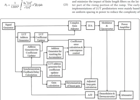
The block diagram shown in Figure 3 shows the simula-tion platform used in the proposed design.
This platform has been implemented using Agilent ADS software. Because, each block has been implemen-ted at component level, so details of each component have not being given deliberately. The training signal is a tone having an increasing magnitude, i.e., a ramp. The tone is generated by uniformly increasing the amplitude of the in-phase and quadrature component of the com-plex baseband signal. The shape of training ramp is shown in Figure 4.
Only the rising portion of the ramp is used by the adaptation algorithm in the calculation of the predistor-tion funcpredistor-tion. The hold and trailing ramp porpredistor-tions are included to smooth the transition between power levels and minimize the impact of finite length filters on the lat-ter part of the rising portion of the ramp. The early implementations of LUT predistorters were mainly based on uniform spacing in power to reduce the complexity of
the LUT address calculation. In the proposed implemen-tation, an optimal spacing scheme for LUT has been used. Optimal spacing has been achieved by applying a suitable companderC(r) to the amplitude signal prior to
addressing the LUT. Here, a set of compandersCrand
Cθis used that minimizes the total residual nonlinear
dis-tortion power at the output of the PA. To simplify the derived mathematical expressions, it is assumed that the input signal’s amplitude and the amplifier’s gain are nor-malized to unity. By using a similar approach given in [11], the value ofCrandCθhas been found as
Cρ(r) = wρ(r) 1/
5
h1 0wρ(r)
1/ 5dr
(24)
And
Cθ(r) = wθ(r) 1/
5
h1 0wθ(r)
1/ 5dr
(25)
where
wρ(r) =p(r) andwρ(r) =|fρ(r)hθ(r)| ˆp(r) (26) p(r) and pˆ(r) are the PDFs of the input amplitude and predistorted amplitude, respectively. Also by using an optimal compander, the total residual distortion power at the PA output remains inversely proportional toN4 as given in Equations (22) and (23) from simulation results it has been observed that the residual distortion power decreases by 12 dB when the LUT size is doubled as opposed to 6 dB. Thus, combination of linear inter-polation with optimal spacing results in higher improve-ments in PA nonlinearity.
Here, one thing that must be considered is that the compander is implemented as an LUT. It is therefore cri-tical that the additional memory requirements do not off-set the gains obtained from using optimal spacing. Thus, the compander has to be implemented as a uniformly spaced, linearly interpolated LUT of sizeL, forming a piece-wise linear function. From simulation results, it has been observed that as compared to uniform spacing the value of error vector magnitude (EVM) improves by about 10 dB when the LUT size was kept as 256. Also it
was observed that as the size of Lhas been increased
beyond 256, no much improvement was found in EVM. Also when both uniform spaced and optimal spaced pre-distorters were implemented using VHDL synthesis, the gate count has shown almost two times reduction in case of optimally spaced compander.
The LUT address generation component translates the magnitude of the baseband input signal into a LUT address using power addressing schemes. The LUT is implemented using the LUT_RAM and the number of entries in the LUT is taken as 256. The LUT is initia-lized at the outset of the simulation using values read from a pair of text files. The text files have been stored in the data directory, so a path need not be provided Figure 4Training ramp.
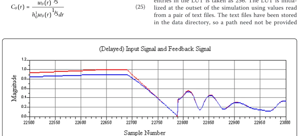
along with the name of the text file. The accuracy of the open loop gain calculation dependents upon the accu-racy of the estimation of the delay in the feedback path. The input signal must be delayed precisely by an amount equal to the delay in the feedback path. The delay in the feedback path is estimated by calculating the correlation between the magnitude of the input sig-nal and the magnitude of the feedback sigsig-nal. The use of the magnitude of the signals has the benefit of not requiring phase synchronization in the feedback path. Because the delay in the feedback path will not necessa-rily be equal to an integer number of DSP sample peri-ods, interpolation is employed to more precisely align the input and feedback signals. Figure 5 shows the delay calculation between input signal and feedback signal.
The correlation between the input and feedback signal is performed on a modulated signal that precedes the training signal because the gain compression of the amplifier makes the accuracy of the correlation over the training signal suspect. In addition, because the envelope of the modulated signal will typically have a PDF such that it spends much of its time within the linear operat-ing region of the amplifier, correlation usoperat-ing the modu-lated signal becomes more reliable. However, because the modulated signal is stochastic, the statistics of the modulated signal, as well as the size of the data block over which the correlation operation is performed will
Figure 6Magnitude entries of LUT for different training ramps.
Figure 7Phase entries of LUT for different training ramps.
impact the accuracy of the delay estimation. In general, the accuracy of the estimation improves as the block size increases. Unfortunately, a larger block size requires more memory and takes longer to perform the estimate. The predistortion function cannot be exactly determined following the transmission of single training ramp and
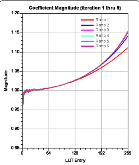
recalculation of the LUT coefficients thereafter. A series of training ramps will have to be transmitted. Although significant improvement in the ACPR of the amplifier should be observed even after a single training ramp, yet simulations have shown that the predistortion function can converge to a solution after only six training ramps. Figure 9Output signal.
PA Output
Power (dBm)
Figures 6 and 7 show the magnitude and phase LUT entries for different training inputs. The final magnitude and phase LUT entries have been shown in Figure 8.
To evaluate the performance of the proposed LUT-based adaptive digital predistorter, the input and output signals of PA have been plotted as shown in Figures 8 and 9, respectively.
The spectrum of the output with and without predis-tortion is shown in Figure 10. The spectrum shows the capability of the proposed design in suppressing signal re-growth. Calculations show that the proposed LUT-based adaptive digital predistorter reduces EVM to 18.14% and ACLR by 54.19 dB.
4. Conclusions
In this study, a low complexity adaptive digital predis-torter with much higher convergence rate as compared to other LUT-based adaptive digital predistorters has been presented. Six training ramps have been used to get high degree of convergence. Although the proposed design shows better performance in terms of reducing EVM and improving ACLR, yet future work will be focused on FPGA implementation of the proposed tech-nique with less hardware requirements.
Competing interests
The authors declare that they have no competing interests.
Received: 26 September 2011 Accepted: 9 February 2012 Published: 9 February 2012
References
1. T Schubert, E Kim,Active and Nonlinear Electronics, (John Wiley, New York, 1996)
2. A Isidori,Trends in Control, (Springer-Verlag, London, 1995)
3. G Goodwin, K Sang Sin,Adaptive Filtering Prediction and Control, (Prentice-Hall, New Jersey, 1984)
4. KJ Muhonen, M Kavehrad, R Krishnamoorthy, Look-up table techniques for adaptive digital predistortion: a development and comparison. IEEE Trans. Veh. Technol.49(5), 1995–2002 (2000). doi:10.1109/25.892601
5. J Kim, K Konstantinou, Digital predistortion of wideband signals based on power amplifier model with memory. Electron Lett.37(23), 1417–1418 (2001). doi:10.1049/el:20010940
6. S Kusunoki, K Yamamoto, T Hatsugai, H Nagaoka, K Tagami, N Tominaga, K Osawa, K Tanabe, S Sakurai, T Iida, Power-amplifier module with digital adaptive predistortion for cellular phones. IEEE Trans. Microwave Theory Techn.50(12), 2979–2986 (2002). doi:10.1109/TMTT.2002.805137 7. W Woo, JS Kenney, A predistortion linearization system for high power
amplifiers with low frequency envelope memory effects, in2005 IEEE MTT-S International Microwave Symposium Digest, vol. 4. Atlanta, USA, 12–17 (4 June 2005)
8. W Woo, MD Miller, JS Kenney, A hybrid digital/RF envelope predistortion linearization system for power amplifiers. IEEE Trans. Microwave Theory Techn.53(1), 229–237 (2005)
9. M Faulkner, M Johansson, Adaptive linearization using predistortion experimental results. IEEE Trans. Veh. Technol.43, 323–332 (1994). doi:10.1109/25.293651
10. A Gersho, Principles of quantization. IEEE Trans. Circ. Syst.25, 427–436 (1978). doi:10.1109/TCS.1978.1084497
11. JK Cavers, Optimum table spacing in predistorting amplifier linearizers. IEEE Trans. Veh. Technol.48, 1699–1705 (1999). doi:10.1109/25.790551
doi:10.1186/1687-1499-2012-43
Cite this article as:Singla and Sharma:Low complexity look up table based adaptive digital predistorter with low memory requirements. EURASIP Journal on Wireless Communications
and Networking20122012:43.
Submit your manuscript to a
journal and benefi t from:
7Convenient online submission 7Rigorous peer review
7Immediate publication on acceptance 7Open access: articles freely available online 7High visibility within the fi eld
7Retaining the copyright to your article