R E S E A R C H
Open Access
Design of a new scheme for multi-hop wireless
networks using decode-and-forward strategy
Iker Alustiza
*, Mikel Hernaez and Pedro Crespo
Abstract
This paper proposes a Decode-and-Forward (DF) relaying scheme for the multi-hop transmission in wireless networks, where the information generated by an independent source has to be sent to a far destination based on
multiple-relay cooperation. The proposed DF scheme blends together convolutional channel coding with linear combination of blocks of data over a finite field using very short block lengths (K=13). We provide an extrinsic information transfer (EXIT) chart analysis to understand the good performance behavior of the proposed scheme when compared with other referenced schemes using much larger block lengths. This fact is corroborated by a set of Monte Carlo simulations. Moreover, the proposed DF scheme is suitable for large multi-hop networks since a
negligible performance degradation is obtained when adding more hops.
Keywords: Multihop transmission; Wireless networks; Decode-and-forward; EXIT charts
1 Introduction
In a multihop network, the data transmission between the source and the corresponding destination is realized with the aid of intermediates nodes (relays). These networks have been the focus of an intense research in the recent years, where Multihop Communication has been shown to be an effective method for establishing connectivity between nodes of a network where direct transmission is not feasible due to coverage or battery life issues [1-5].
In [1-3] and reference therein, several theoretical aspects of multihop network were presented. Concretely, in [1], efficient routing protocols for several power allo-cations in fading were presented. Based on these proto-cols, the authors in [4] proposed a Decode-and-Forward (DF) relaying strategy based on combining together low-density parity-check (LDPC) codes with a linear combi-nation of blocks of data over a finite field. It was showed that for blocks ofK = 1, 500 information bits, the pro-posed scheme outperformed two reference schemes based on the previous works addressing similar problems [5,6].
In the current manuscript, we propose a DF relaying strategy which uses a terminated convolutional code and an improved version of the non-binary block-wise linear
*Correspondence: [email protected]
Centro De Estudios e Investigaciones Técnicas de Gipuzkoa (CEIT) and TECNUN (University of Navarra), 20008 Donostia-San Sebastián, Spain
combination of [4]. At each node, the decoding scheme is based on applying the sum-product algorithm (SPA) to a factor graph [7] describing thea posteriori probabil-ity of the communication scenario at the corresponding node. By using blocks of onlyK = 13 information bits, the performance of the proposed scheme outperforms the scheme of [4] (and consequently, [5,6]) where 1,500 bits were used, making the proposed scheme particularly attractive for low-latency applications.
This paper, extending the work carried out in [8], pro-vides an extrinsic information transfer (EXIT) chart anal-ysis [9] to understand the good performance behavior of the proposed scheme based on short length codes. Although EXIT charts provide good BER convergence predictions only for long-length codewords (which is not our case), it gives us a good insight on why the proposed system outperforms the LDPC-based system. Moreover, this same tool has been previously used with short-length terminated convolutional codes by the authors in [10] with successful results. For a more accurate prediction of the BER convergence for short length codes, we refer to [11], where a method for computing lower bounds based on a EXITbandchart is proposed.
The rest of the manuscript is organized as follows: Section 2 introduces the network model, whereas the pro-posed DF scheme is presented in Section 3. In Section 4, an analysis of the code based on EXIT charts is performed.
Section 5 discusses the obtained Monte Carlo simulations results, and finally, Section 6 concludes the manuscript.
2 Network model
We study the problem where a user wants to transmit data to a destination through a mutihop wireless network. For the sake of simplicity, we have imposed a straight-line geometry and unity distance between two consecutive nodes, so we can easily compute distances and signal attenuations between nodes. In order to avoid possible interferences in the network, we design the system in time division multiple access (TDMA) mode.
The nodes are assumed to work in half-duplex mode; hence, a node can either receive or transmit data, but not both at the same time. Therefore, the data is trans-mitted in a progressive way through the simplified linear network. That is, one node can listen to all the previous nodes but not to the following ones. Due to the wireless nature of the signals, we consider Rayleigh fading and path loss attenuation. Finally, due to the wireless environment and following [4,5], we do not constrain the transmission range of each node to one hop, as done in [1-3].
LetM= {s, 1,. . .,m−1,m}denote the set of nodes in the network, wheresandmare the source and destination nodes, respectively. We defineR= {1,. . .,m−1} ⊂Mas the subset formed by the intermediate nodes (relays), and Tj = {s, 1,. . .,j−1} ⊂M(forj = 1,. . .,m) as the sub-set of nodes from which nodejreceives their transmitted symbols. Figure 1 depicts the network model.
Regarding the links between nodes, we consider inde-pendent (orthogonal) quasi-static Rayleigh flat-fading channels and channel state information at the receivers (coherent detection), where the t-sampled baseband (complex) link input-output (S-Y) relation from nodeito nodejat timetis given by
Yt= |ij|
d−ijδSt+Ntij, St∈C (1)
withd−δ modeling the path loss attenuation, wheredis the number of hops (units) between the transmitting and the receiving node andδis the attenuation exponent. The fading coefficientand the additive Gaussian noise Nt are circularly symmetric complex Gaussian random vari-ables of zero mean and variance one andN0, respectively.
A realization ofis assumed to remain constant for the duration of the transmitted block.
3 Proposed DF scheme
Like most of the DF schemes, the proposed scheme can be partitioned into two blocks: the decode block, where the information sequence is estimated; and the forward block, where the estimated sequence is encoded and forwarded. In this case, the forward part at the source node is imple-mented in a different manner than the ones at the relay nodes; therefore, it is explained first.
We consider an i.i.d binary source that generates infor-mation blocks U ∈ {0, 1}K. Then, the information
sequence is encoded by a rate R = K/N
convolu-tional code. The resulting encoded binary codewordC
{Cn}Nn=1 ∈ {0, 1}N is interleaved by a random interleaver
yielding the interleaved sequenceXwithXn = C(n). Finally,Xis mapped into the sequence of symbolsS∈SM chosen from a 2q-ary complex signal constellationS ⊂C according to the bit-to-symbol mappingμ : {0, 1}q → S (e.g., Gray mapping), thus,M=N/q.
Since we next present the operations performed at each relay node, we will intentionally omit any references to the particular nodej. However, when considering the entire network, we will use the upper indexjto discern between different nodes.
3.1 Forward
At each nodej∈R, the decode block, which is explained later, outputs the estimated information sequence U, which is then encoded and interleaved using the afore-mentioned convolutional code and interleaver. The result-ing binary sequence X is partitioned into the q-length sub-sequencesXl {Xlq+i}iq=1, wherel = 0,. . .,M−1.
Letφ : Fq2 → F2q denote the one-to-one mapping from
q-length binary sequence1into elements ofF
2q. Thus, the
into signal points of the 2q-ary constellationS. That is, for t=1,. . .,M/2 andl=t−1
St=μF2q
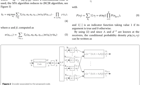
the network so that all the vector coefficients in the net-work are linearly independent. We further constrain the election to {hi}i=1,2 = 0. Finally, note that the length, N/2, of the sequences transmitted by the relays is half of the length,N, of the sequences transmitted by the source. Figure 2 provides a graphical explanation of the encoding process.
3.2 Decode
Let us consider an arbitrary nodej∈R ∪ mthat receives the sequences sent by the nodesi∈ Tj(i.e., all the nodes located at its left-hand side, see Figure 1). This node has Tjincoming links with received sequences(y1, ...,y|Tj|). For the sake of clarity, through this sub-section, we define
y(y1, ...,y|Tj|)and denotey
tas the|Tj|symbols received at time instantt, which are related to the elementsVland Vl(see (1) and (2)).
The aim of the decoder is to implement a bitwise MAP decoding. That is, to find the values{uk}Kk=1that are most used, the SPA algorithm reduces to (BCJR algorithm, see Figure 3)
are the forward and backward messages passed from the adjacent state nodes to the factor nodeTk given by the Trellis of the convolutional code. Notice that in our case, the initial value α and β is known (assuming that the convolutional code is terminated). The local functions Tk(sk,uk,ck,sk+1)describe the transitions allowed in the
Trellis, indicating which combination of variables in its argument is valid. Moreover,ck are theN/K coded bits
{cn}associated toukandγ are the the channel likelihoods of the coded bits. Due to the proposed forward block, these likelihoods are related to the interleaved binary sym-bolsxlq+i through the |Tj| incoming links, i.e.,γ (cn) =
γ (x−1(lq+i)), whereγ (xlq+i)∝p(y|xlq+i).
Since the channel is memoryless and assuming that the interleaved sequence is i.i.d., this probability can be factorized as
and 1[·] is an indicator function taking value 1 if its argument is true and 0 otherwise.
By using (2) and since and d−δ are known at the receivers, the conditional probability density p(yt|vl,vl) can be written as
Figure 3BCJR algorithm for the convolutional code part of the
where · denotes the euclidian norm.
Therefore, the marginalization of (3) can be efficiently performed by the SPA applied to the factor graph (Figure 4) derived from the factorization of PU|Y(u|y) given by (4)–(9).
4 Analysis of the code based on EXIT charts
As it is shown in Figure 4, the factor graph of the decoder used by the SPA algorithm can be split in two blocks:
Figure 4Factor graph employed for the decoding.
The linear combination (LC) block and the convolutional code block. Due to the iterative nature of this decoding algorithm, EXIT charts are a good method for visually understanding the behavior of the proposed scheme [9]. Given a code, the EXIT function associated is defined by the relation between thea priorimutual information at the input of the decoder (commonly denoted as Ia) and the corresponding extrinsic mutual informationIe at its output, i.e.,Ie=T(Ia).
Givenqandh, we denote the transfer function of the LC decoder asILC
e = Thq(I LC
a), i.e., the extrinsic mutual infor-mation at the output of the LC decoder. Notice that,Thq(0) andThq(1)represent the extrinsic information at the out-put of the LC decoder with noa prioriand fulla priori information on the information bits, respectively. As the mutual information at the input of the channel decoder ICC
a is equal to IeLC, the extrinsic mutual information at the output of the convolutional decoder is a function of ILC
e , that is,IeCC = TCC(IeLC). Thus, for a successful decod-ing procedure, there must be an open gap between both EXIT curves so that the iterative decoding can proceed fromICC
e = 0 toIeCC = 1. Otherwise, when both transfer functions cross, the iterative process will stop at a given extrinsic mutual information of the source bitsICC
e <1. Figure 5a plots the EXIT charts for the LC code and for anR=1/2 convolutional channel code, for different net-work coefficientsh= (h1,h2)andq = 4. For the sake of
clarity, we focus the analysis on the first node and, follow-ing the study in [12], it is also assumed an AWGN channel (i.e.,s,1 = 1) between this node and the source. Never-theless, as it is shown in the EXIT chart study of [12], the same insight is obtained when assuming fading channels between nodes.
To compare the performance of our scheme with the one implemented in [4], Figure 5b plots the EXIT chart of an LDPC code of rate R = 0.416. Notice, however, that a LDPC code is composed of several subgraphs, thus, several transfer functions (one for each compounding sub-graph) are obtained and a direct representation of these functions will result in an N-dimensional EXIT chart. By converting theN-dimensional EXIT chart into a two-dimensional EXIT chart, for example, by using the EXIT Chart Projection Algorithm proposed in [13], the same analysis could still be applied.
When using the convolutional code, one can observe from Figure 5a that the gap between the LC code and channel code curves is open for most of the network coefficients. On the contrary, in the LDPC code case, (Figure 5b) shows that this gap is close for all of the
(h1,h2)coefficients combinations. Therefore, the iterative
decoding process will stop before reachingILDPC
e =1. Both
EXIT charts in Figure 5 are calculated with the samea pri-orimutual informationILC
a
b
Figure 5EXIT charts of the LC decoder. Different network coefficients along with our scheme(a)and the LDPC code from [4](b).
signal-to-noise ratio (SNR). Hence, to open the gap for the LDPC case a larger SNR will be required.
In light of the above analysis, it is expected that our scheme will outperform the scheme in [4] which is based on codeword lengths two orders of magnitude higher. This assumption is corroborated by the simulation in the next section.
5 Results
In order to assess the performance of the proposed code, several Monte Carlo simulations have been run using a 4-state [ 5, 7]8non-systematic rate-1/2 convolutional code2.
The source generates K = 13 information bits, and a zero-bit tail is appended at the source sequence in order to properly terminate the convolutional code. Specifically, we add 3 zeros so the block entering the convolutional code has 16 bits, and hence, the encoded sequence has
N = 32 binary symbols. We have considered a 16-QAM
constellation (i.e.,q=4 andM=8 complex dimensions) andμto be the Gray mapping. Moreover,δ has been set to 4 and the interleaver (·) has been randomly gener-ated with a spread factor ofq = 4. Finally, the number
of iterations completed by the decoding algorithm at the relays is set 100.
The number of nodes has been set to |M| = 5.
That is, the source transmits its message to the destina-tion with the aid of three intermediate nodes. Therefore, a total of 20 baseband symbols (i.e., complex dimen-sions) are transmitted through the system leading to a spectral efficiency of ρS = 13/20 (information bits per complex dimension). Finally, the vector coefficients are chosen as {(1, 0),(0, 1),(1, 1),(2, 1),(1, 2)}, and, for the sake of simplicity, we have assumed equal out-put power at each of the compounding nodes of the network.
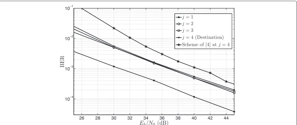
The first set of simulations aims at analyzing the perfor-mance of the DF scheme at the different relay nodes and therefore, at different distances from the source. Figure 6 plots the bit error rate (BER) versusEb/N0at nodesj =
Figure 6BER performance of the proposed scheme at all the nodes for 100 iterations. Also plotted the performance of [4] at the destination.
the figure also shows the BER performance of the scheme proposed in [4] at the destination (j=4).
It can be observed that, after the first hop (j = 1), the performance at high values of SNR for the remain-ing nodes (j = 2, 3, 4) is almost the same. In fact, for SNR = 30 to 40 dB, the BER curves forj = 2, 3, 4 even overlap. The main reason for this behavior is the following: On the one hand, for small number of relays, the incre-ment of diversity is not significant due to the pathloss attenuation suffered by the signals. On the other hand, as the number of relays increases, the achieved diversity starts to increase since the pathloss attenuation becomes less significant due to the increment of incoming signals. Hence, adding more relays in order to reach a distant point practically does not degrade the performance of
the system, which makes the proposed scheme suitable for multi-hop wireless networks. This advantage becomes more evident in Figure 7 where the proposed scheme is tested over a larger network with 10 nodes (|M| = 10). The performance of this larger network remains practically constant when the SNR is sufficiently high (SNR≥30 dB).
It can also be said that the proposed DF scheme outper-forms the schemes presented in [4] in more than 3 dB (and consequently [5] and in [6]). This fact confirms the insight given by the previous EXIT charts study. Furthermore, it is important to remark that, for the same spectral efficiency, the proposed scheme uses a total of 20 complex dimen-sions in comparison to the 4,500 used in the referenced scheme.
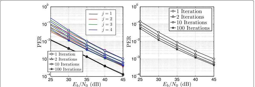
Figure 8Performance of the proposed scheme in terms of PER for different amount of iterations at the relays and 100 iterations at the destination. At every receiving node of the network (j=1, 2, 3, 4) on the left and only for the destination (j=4) on the right.
Another interesting application of the proposed scheme is networks in which the relays share their resources with other networks. In this case, the number of iterations at the relays should be kept small to reduce their com-putational load. However, a performance degradation is expected for choosing a low number of iteration. To check the performance of this scheme, a different set of simula-tions has been studied. This is shown in Figure 8 which plots the packet-error rate (PER) versusEb/N0at the
des-tination where we fix the number of iterations at the destination in 100, and vary the iterations performed at the relays with values from the set{1, 2, 10, 100}. As previ-ously, the number of nodes of the network has been set to
|M| =5.
Figure 8 (left) shows that at the first relay (j=1) there is a small improvement in the performance by increasing the number of iterations. This situation changes completely for the remaining nodes where there is approximately a 4 dB gap between the performance for 1 iteration and 100 iterations. Perhaps, it is more insightful to focus on the performance at the destination (j=4), plotted in Figure 8 (right). In this figure, we see that when the number of iter-ations at the relay is set to 2, 10, and 100, gains of 2 dB, 3.5 dB, and 4 dB are obtained, respectively, with respect to a single iteration. Notice also that going from 10 itera-tions to 100 iteraitera-tions conveys a gain of only 0.5 dB; hence, the gain obtained for performing more than 10 iterations is negligible, which makes the scheme suitable for relays with shared resources.
6 Conclusion
We have presented a decode-and-forward scheme for multihop wireless networks with orthogonal channels. The proposed scheme blends together convolutional channel coding with linear combination of blocks of data over a finite field. According to EXIT chart analysis and
simulation results, the proposed DF scheme clearly out-performs previously schemes in the literature by using only a total of 20 complex dimensions. This latter fact makes the proposed scheme particularly attractive for low-latency applications. Furthermore, it is also suit-able for large multihop networks as a negligible perfor-mance degradation is obtained when adding more hops. Finally, this scheme is suitable for relays with shared resources since most of the iterative gain at the decod-ing is achieved in less than 10 iterations of the decoddecod-ing process.
Competing interests
The authors declare that they have no competing interests.
Acknowledgements
This work was supported in part by the Spanish Ministry of Science & Innovation through theCOMONSENS(CSD200800010) andCOSIMA
(TEC2010-19545-C04-02) projects, as well as by Cátedra Telefónica at University of Navarra.
Received: 10 October 2014 Accepted: 26 April 2015
References
1. R Babaee, NC Beaulieu, Cross-layer design for multihop wireless relaying networks. IEEE Trans. Wireless Comm.9, 3522–3531 (2010)
2. E Morgado, I Mora-Jimenez, JJ Vinagre, J Ramos, AJ Caamano, End-to-end average ber in multihop wireless networks over fading channels. IEEE Trans. Wireless Comm.9, 2478–2487 (2010)
3. R Babaee, NC Beaulieu, Exact evaluation of ergodic capacity for multihop variable-gain relay networks: a unified framework for generalized fading channels. IEEE Trans. Vehicular Tech.59, 4181–4186 (2010)
4. M Hernaez, PM Crespo, inProceedings of VTC-Spring11. A novel scheme for message-forwarding in multi-hop ad-hoc wireless networks (IEEE, Budapest, Hungary, 2011)
5. X Bao, J Li, inProceedings of SECON. Progressive network coding for message-forwarding in ad-hoc wireless networks (IEEE, Reston, USA, 2006) 6. C Hausl, F Schreckenbach, I Oikonomidis, G Bauchi, inProceedings of
Allerton, University of Illinois, USA. Iterative network and channel decoding on a tanner graph, (2005)
8. M Hernaez, I Alustiza, PM Crespo, JD Ser, inProceedings of VTC-Fall13. A decode-and-forward scheme for multihop wireless networks (IEEE Las Vegas, USA, 2013)
9. J Hagenauer, inProceedings of EUSIPCO. The exit chart: Introduction to extrinsic information transfer in iterative processing (EURASIP Vienna, Austria, 2004)
10. M Hernaez, PM Crespo, JD Ser, Flexible channel coding approach for short-length codewords. IEEE Comm. Lett.16(9), 1508–1511 (2012) 11. JW Lee, RE Blahut, Lower bound on ber of finite-length turbo codes based on exit characteristics. IEEE Comm. Lett.8(4), 238–240 (2004) 12. M Hernaez, PM Crespo, JD Ser, On the design of a novel joint
network-channel coding scheme for multiple access relay channels. IEEE J. Sel. Areas Commun.31(8), 1368–1378 (2013)
13. F Brannstrom, LK Rasmussen, AJ Grant, Convergence analysis and optimal scheduling for multiple concatenated codes. IEEE Trans. Inf. Theory.51, 3354–3364 (2005)
Submit your manuscript to a
journal and benefi t from:
7Convenient online submission 7 Rigorous peer review
7Immediate publication on acceptance 7 Open access: articles freely available online 7High visibility within the fi eld
7 Retaining the copyright to your article


![Figure 5 EXIT charts of the LC decoder. Different network coefficients along with our scheme (a) and the LDPC code from [4] (b).](https://thumb-us.123doks.com/thumbv2/123dok_us/948021.1115747/5.595.61.540.81.433/figure-exit-charts-decoder-different-network-coefficients-scheme.webp)