1
Design and Simulation of Voltage Amplidyne System using
Robust Control Technique
Mustefa Jibril1, Messay Tadese2, Eliyas Alemayehu Tadese3
1 Msc, School of Electrical & Computer Engineering, Dire Dawa Institute of Technology, Dire Dawa,
Ethiopia
2 Msc, School of Electrical & Computer Engineering, Dire Dawa Institute of Technology, Dire Dawa,
Ethiopia
3 Msc, Faculty of Electrical & Computer Engineering, Jimma Institute of Technology, Jimma, Ethiopia
Abstract
In this paper, modelling designing and simulation of a simple voltage amplidyne system is done using robust control theory. In order to increase the performance of the voltage amplidyne system with H optimal control synthesis and H optimal control synthesis via -iteration controllers are used. The open loop response of the voltage amplidyne system shows that the system can amplify the input 7 times. Comparison of the voltage amplidyne system with Hoptimal control synthesis and Hoptimal control synthesis via -iteration controllers to track a desired step input have been done. Finally, the comparative simulation results prove the effectiveness of the proposed voltage amplidyne system with H optimal control synthesis controller in improving the percentage overshoot and the settling time.
Keywords: Amplidyne, Hoptimal control synthesis controller, Hoptimal control synthesis via -iteration controller
1. Introduction
An amplidyne is an electromechanical amplifier invented prior to World War II by Ernst Alexanderson. It consists of an electric powered motor riding a DC generator. The signal to be amplified is carried out to the generator's field winding, and its output voltage is an amplified reproduction of the field current. The amplidyne is used in enterprise in excessive power servo and manage systems, to increase low power manage signals to control powerful electric powered motors. An amplidyne incorporates an electric powered motor which turns a generator on the identical shaft. Unlike an ordinary motor-generator, the cause of an amplidyne isn't always to generate a consistent voltage but to generate a voltage proportional to an Input current, to modify the input. The motor affords the power, turning the generator at a constant velocity, and the signal to be amplified is applied to the generator's field winding.
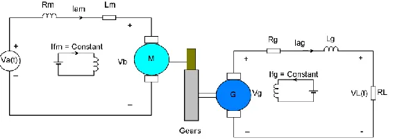
2. Mathematical Modelling of the system
2
Figure 1 Voltage amplidyne system The Motor Side
Assume
The stator current is constant therefore the magnetic flux is constant
t K If f
1 The motor torque is proportional to the armature current and the flux
1
2m m a a
T t K i t K i
The voltage vb is proportional to the angular speed of the motor
2
3b m
V t K t
Applying KVL to the motor circuit
4 a
m m a b a
di t
L R i t V t V t
dt
Substituting Equation (3) in to Equation (4) yields:
2 5
a
m m a m a
di t
L R i t K t V t
dt
The rotational equation of the motor is
1 6
m
m m m m a
d t
J B t T t K i t
dt
Taking the Laplace Transform of Equation (5) and Equation (6)
2
7a m m m a
I s sL R K s V s
1
8m s sJm Bm K Ia s
3
Substituting Equation (8) into Equation (7) for Ia yields the transfer function between the input voltage and the output angular speed
1
1 2
9 m
a m m m m
s K
V s sJ B sL R K K
For the generator
The field current is constant therefore the flux is constant
The generated voltage is proportional to the angular speed, flux and field current
10 g g fgV K I
fg f
I K
3 11
g g f
V K K K
Applying KVL to the generator circuit
12
ag
g g L ag g
di t
L R R i t V
dt
Substituting Equation (10) in to Equation (12) yields:
3 13
ag
g g L ag
di t
L R R i t K t
dt
Taking the Laplace Transform of Equation (13)
3
14ag g g L
I s sL R R K s
The transfer function between the input angular speed and the output current is
3
15ag
g g L
I s K
s sL R R
Simply the load voltage is
16L L ag
V s R I s
Substituting Equation (16) in to Equation (15) yields:
3
17L L
g g L
V s R K
s sL R R
4
s N m
s
18 Substituting Equation (18) in to Equation (17) yields:
3
19L L
m g g L
V s NR K
s sL R R
The transfer function between the input motor voltages to the output load voltage is found by combining Equation (9) and Equation (19) which results:
1 3
1 2L L
a g g L m m m m
V s K NR K
V s sL R R sJ B sL R K K
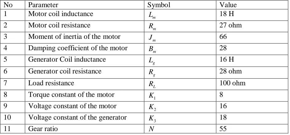
The parameters of the system is shown in Table 1 below. Table 1 System parameter
No Parameter Symbol Value
1 Motor coil inductance Lm 18 H
2 Motor coil resistance Rm 27 ohm
3 Moment of inertia of the motor Jm 66
4 Damping coefficient of the motor Bm 28
5 Generator Coil inductance Lg 16 H
6 Generator coil resistance Rg 28 ohm
7 Load resistance RL 100 ohm
8 Torque constant of the motor K1 8
9 Voltage constant of the motor K2 16
10 Voltage constant of the generator K3 18
11 Gear ratio N 55
The transfer function of the system becomes
3 241.67
9.9 16.1 5.95
G s
s s s
And the state space representation becomes
9.9242 16.1380 5.9529 1
1 0 0 0
0 1 0 0
0 0 41.6667
x x u
5 3.The Proposed Controllers Design2
3.1HOptimal Control Synthesis Controller Design
Hoptimal control synthesis solve the small-gain infinity-norm robust control problem; i.e., find a stabilizing controller F(s) for a system P(s) such that the closed-loop transfer function satisfies the infinity-norm inequality
1 1 sup max 1 1 1
y u y u
T T j
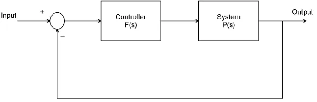
The block diagram of the system with Hoptimal control synthesis controller is shown in Figure 2 below
Figure 2 Block diagram of the system with Hoptimal control synthesis controller
An important use of the infinity-norm control theory is for direct shaping of closed-loop singular value Bode plots of control systems. In such cases, the system P(s) will typically be the plant augmented with suitable loop-shaping filters
The Hoptimal control synthesis controller transfer function is
4 33 220.9956 9.88 16.07 5.926 11.87 37.39 56.39 0.5602
s s s
s s s s
F s
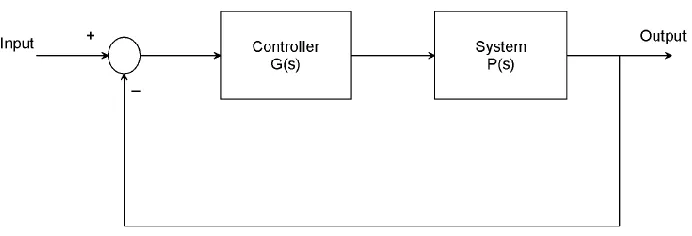
3.2HfOptimal Control Synthesis via -iteration Controller Design
Hoptimal control synthesis via -iteration compute the optimal Hcontroller using the loop-shifting two-Riccati formulae. The output is the optimal “” for which the cost function can achieve under a preset tolerance.
1 1
1 1
min ,;
1 ,;
y u y u
T ga d
T otherind
6
Figure 3 Block diagram of the system with Hoptimal control synthesis via -iteration controller
The Hoptimal control synthesis via -iteration controller transfer function is
4 33 220.5001 4.963 8.071 2.977 13.39 50.62 62.53 0.6202
s s s
s s s s
G s
4. Result and Discussion
4.1Voltage Amplidyne System Open Loop Response
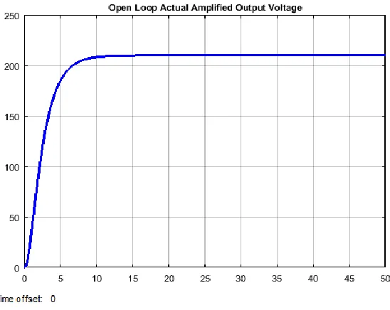
The Simulink model of the open loop voltage amplidyne system and the simulation result of the system for a constant motor voltage input of 30 volt is shown in Figure 4 and Figure 5 respectively.
7
Figure 5 Simulation result
The simulation result shows that the amplidyne output voltage is 210 volt which amplifies the voltage 7 times.
4.2Comparison of the Proposed Controllers for Tracking a Desired Step Amplidyne Voltage
The Simulink model of the voltage amplidyne system with Hoptimal control synthesis and H
optimal control synthesis via -iteration controllers are shown in Figure 6 below
Figure 6 Simulink model of the voltage amplidyne system with Hoptimal control synthesis and Hoptimal control synthesis via -iteration controllers
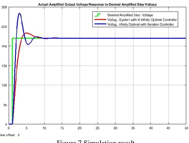
The simulation result of the voltage amplidyne system with Hoptimal control synthesis and H
8
Figure 7 Simulation result
The performance data of the rise time, percentage overshoot, settling time and peak value is shown in Table 2.
Table 2 Step response data
No Performance Data Hoptimal Hoptimal via -iteration
1 Rise time 2.1 sec 2 sec
2 Per. overshoot 4.54 % 22.72 %
3 Settling time 9 sec 11 sec
4 Peak value 230 V 270
5. Conclusion
In this paper, a simple voltage amplidyne system is designed using a DC motor generator combination. In order to improve the performance of the system, a robust control technique with H optimal control synthesis and H optimal control synthesis via -iteration controllers are used. The open loop response of the system shows that a 7 time’s amplification voltage is gained. The comparison of the proposed controllers is done to track a desired step amplified voltage and the results proves that the system with H optimal control synthesis controller improves the settling time and the percentage overshoot than the system with Hoptimal control synthesis via
9 Reference
[1].Dalya H. et al. “Generating High Voltage DC with Cockcroft-Walton Voltage Multiplier for Testing Locally Assemble Electric Field Sensor” IOP Conference Series: Materials Science and Engineering, Vol. 518, Issue 4, 2019.
[2].S Settar et al. “Analysis Study in Principles of Operation of DC Machine” Journal of Advanced Research in Dynamical and Control Systems, Vol. 10, Issue 2, pp. 2323-2329, 2018.
[3].Shulong Tan et al.”Modeling Framework of Voltage Source Converters Based on Equivalence with Synchronous Generator” Journal of Modern Power Systems and Clean Energy, Vol. 6, Issue 1, pp. 1291-1305, 2018.
[4].W.G. Heffron et al. “Effect of a Modern Amplidyne Voltage Regulator on Underexcited Operation of Large Turbine Generators [includes discussion]” IEEE Transactions, Vol. 71, Issue 3, 2017.
[5].Abulfazl H. et al. “Design and Implementation of Direct Power Control System for Brushless DC Generator in Standalone DC Applications” Journal of Electric Power Components and Systems, Vol. 45, Issue 7, 2017.