2017 International Conference on Computer, Electronics and Communication Engineering (CECE 2017) ISBN: 978-1-60595-476-9
Slow-moving Target Detection Method for Airborne MIMO Radar Using
Doppler Frequency Movable Waveform
Yi-duo GUO
1,2,*, Fu-ping YU
1, Jian GONG
1,2and Di SHEN
11Air Force Engineering University, Xi’an, Shaanxi, 710051, China
2National Laboratory of Radar Signal Processing, Xidian University, Xi’an, Shaanxi, 710071, China
*Corresponding author
Keywords: MIMO radar, Target detection, Clutter suppression, Doppler frequency movable waveform.
Abstract. For an airborne radar system, the detection of moving target under the ground clutter has become the research hotspot to worldwide scholars. And the detection of the slow-moving target near the main clutter area is now regarded as one of the difficulty problem. In order to reduce the Minimum Detectable Velocity (MDV) of moving target, a novel slow-moving target detection method is presented for airborne MIMO radar, which transmits Doppler frequency movable waveform (DFMW). By combining the advantages of the MIMO radar and the DFMW, the proposed method could realize the suppression of ground clutter and the detection of the slow-moving target near main clutter area effectively. Simulation results confirm the effectiveness of the proposed method.
Introduction
Space-time adaptive processing (STAP) is an effective technique to suppress strong ground clutter and detect slow-moving targets in airborne radar systems [1], [2]. Originally, the theory of STAP is developed for conventional airborne phased array radar system, which can be viewed as a single-input multiple-output (SIMO) radar system. However, although STAP technique for SIMO radar has been well studied, its capability of clutter suppression need to further improve. Compared with SIMO radar, multiple-input multiple-output (MIMO) radar enjoys better spatial resolution because of the much larger virtual array than the physical array [3]. Therefore, focusing on the significant potentials for clutter suppression, MIMO-STAP technique has drawn considerable attentions in recent years [4], [5].
On the principle of STAP theory, the degree of freedom (DOF) of STAP processors should be larger than that of clutter. Therefore, the estimation of clutter DOF for MIMO radar has been
intensively studied. Chen gave the extension of Brennan’s rule to the MIMO radar case in [6]; Xie
estimated the clutter DOF of the MIMO-phased array radar in [7]; Li derived the estimation of clutter
DOF of wideband MIMO radar in [8]. These researches have made great contributions to the successful design of STAP processors for MIMO radar.
In this paper, we develop a effective detected method for slow-moving target by combining the advantages of the MIMO radar and the DFMW, the proposed method could realize the suppression of ground clutter and the detection of the slow-moving target near main clutter area.
Signal Model for Airborne MIMO Radar
Consider a monostatic side-looking airborne MIMO array radar with N receiving elements uniformly
spaced by dR
/ 2 and M transmitting elements uniformly spaced by dT dR d
2, where
is the wavelength. Assume that the carrier aircraft is at the altitude H with the constant movingvelocity V. The number of pulses at a coherent processing interval (CPI) is K, and the pulse repetition
frequency (PRF) is fr. The system transmits an orthogonal waveform set with carried frequency f0
(
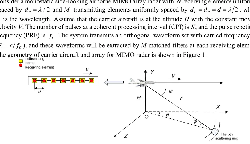
c f0), and these waveforms will be extracted by M matched filters at each receiving element. [image:2.612.87.517.148.396.2]The geometry of carrier aircraft and array for MIMO radar is shown in Figure 1.
Figure 1. The geometry of carrier aircraft and array for MIMO radar.
Thus, for the mth waveform and kth pulse, the clutter echoes on the nth receving element after
matched-filering can be expressed as
, , 0
1
exp 4 exp 2 1 1 1
Q
c c c
m n k q sq
q
x j rf c j n k m f
(1)where QMNK is the number of clutter patches;
q is the reflect coefficient of clutter,
0
cos
c
sq q
f df c
is the spatial frequency of the qth clutter patch, cos( )
q is the directionalcosine and c 2
r
V df
.Assume that there exist one target in the same range cell as the clutter, so the signal echo of target
on the nth receving element for the mth waveform and kth pulse can be expressed as
, , exp 4 0 exp 2 1 1 1
s s s
m n k s
x j rf c j n k m f (2)
where
0
coss s
f df c
is the spatial frequency of the target,
s 2V dft r , Vt is movingvelocity of target, cos( )
is the directional cosine, is the reflect coefficient of clutter.Detection Method for Airborne MIMO Radar using DFMW
Assume the MIMO radar transmit Doppler frequency movable waveform (DFMW) which is stepped-frequency waveform. The carrier frequencies of the transmitting array elements are
0 1
n
where f is the frequency increment across the transmitting elements, f0 is the reference carrier
frequency, f and f0 satisfy f f0.
The transmitted signal of the nth element can be expressed as
E m
exp 2
m
,0 rs t t j f t t T
M
(4)
where E is the total transmitted energy, r 1
r
T f
denotes the radar pulse repetition duration, m
tindicates the unity-energy baseband waveform of the nth element, and they satisfy
1,0,
r
k l
T
l n t t dt
l n
(5)where denotes arbitrary time delay, the superscript * denotes conjugate operation.
According to Equation (1), in the MIMO radar with DFMW, the clutter echoes on the nth receving
element for the mth waveform and kth pulse can be expressed as
, , 1 1 0exp 4 exp 2 1 1 1
exp 1 cos exp 1 4 cos
4
exp 1 1 cos
Q
c c
n
m n k q sq
q
Q
q q q
q
q r
rf
y j j n k m g
c
j n j m r f c
V
j k f m f
f
(6)where c
cos
sq n q
g df c
is the spatial frequency of the qth clutter patch, cos( )
q is thedirectional cosine, q qexp
j4rf0 c
.For certain pulse (i.e. the kth), the vector form of ym n k, , can be written as
,
, ,
1,:
Q
c c c
c q r q t q f q
q
k
y A A A (7)
where
0
4
exp 1 cos
q q q
r
V
j k f
f
,
T
, 1,exp cos( ) ,...,exp ( 1)cos( )
c
r q j q j N q
A is
the receiving spatial steering vector of clutter, c, 1,exp
cos( ) ,...,exp
( 1)cos( )
Tt q j q j M q
A is
the transmitting spatial steering vector of clutter, c , = 1 exp 4
1 cos( )
,f q q
r
V r
j k f
c f A ,
T,exp 4 1 1 cos( q)
r
V r
j M k f
c f
, and denote Kronecker and Hadamard
product respectively.
Meanwhile, for the target located in the same range cell as the clutter, its vector form of the kth
pulse can be expressed as
,: s
s s
s k r t f
where s 1,exp
cos
,...,exp
( 1)cos
Tr j j N
A is the receiving spatial steering vector of target,
T1, exp cos ,..., exp ( 1) cos
s
t j j M
A is the transmitting spatial steering vector of
target, s = 1 exp 4 t
1 cos
,f
r
V r
j k f
c f
A ,
T
,exp 4 1 t 1 cos
r
V r
j M k f
c f .
And then, the velocity of the carrier aircraft V is used to compensate its effect on the data of clutter
and target, which can be expressed as
,
, ,
,1
,:
Q
c c c c
c q r q t q f q N V q
q
k
z A A A e A (9)
,: s
s s
cs k r t f N V
z A A A e A (10)
where eN
1,1, ,1
T is an N1 vector,
, = 1 exp 4 1 cos( ) , ,
c
V q q
r
V
j k f
f
A ,
T
4
exp 1 cos( )q 1
r
V
j k M f
f ,
4= 1 exp - 1 cos , ,
s V
r
V
j k f
f
A ,
T
4
exp 1 cos 1
r
V
j k M f
f
.
Using the property of Kronecker and Hadamard product, Equation (9) and (10) can be rewritten as
,
,
1
,:
Q
c c c
c q r q t q q
q
k
z A A A (11)
,: s
s s
s k r t
z A A A (12)
where c= 1 exp
4
, ,exp
4
1
Tq j rcf j rc M f
A , , s= 1
A ,
Texp 4 t 1 cos ,exp 4 1 t 1 cos
r r
V V V V
r r
j k f j M k f
c f c f
, .
Therefore, the transmitting spatial frequencies and receiving spatial frequencies of the clutter and target can be written as follow
1cos( ) 2
2 1 cos( ) 2 c T q c R q r f f c f (13)
2 1 2cos( ) 1 cos
2
1cos( )
2 t s T r s R V V r
f f k f
c f f (14)
2
1 cos
t
r
V V
k f
f
. Therefore, several STAP algorithms can be used to suppress the clutter
based on the different modulation effect on the target and clutter.
Simulation Results
In this section, simulations are conducted to verify the effectiveness of the proposed method. We assume the simulated scenario has the following parameters: monostatic side-looking airborne MIMO array radar with 8 transmitting/receiving uniform elements at the altitude 6000m with constant velocity 140m/s, wavelength 0.23m, so the space of transmitting/receiving array is 0.115m,
clutter-to-noise ratio (CNR) 60dB, and pulse number is 8. A target with normalized Doppler
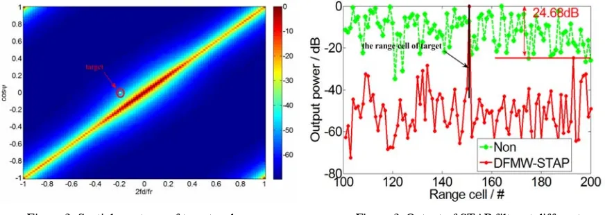
[image:5.612.90.526.359.514.2]frequency -0.2 and spatial frequency 0 is introduced at the location of range cell 151, and the velocity of the target is 15m/s.The spatial spectrum estimation obtained by the proposed method is presented in Figure 2, which demonstrate that the new method could distinguise the clutter and target with high resolution. Figure 3 shows the output power which has been normalized along the range cell for the proposed method. The ‘Non’ line shows that the target is completely buried in the surrounding clutter environment before STAP algorithm adaptive processing. Compared with the ‘Non’ line which can hardly obtain an accurate estimation of the clutter covariance matrix of test cell, the proposed algorithm can effectively suppress the clutter of all range cells, make the output power of No.162 cell 24.68dB beyond the maximum output of other cells, so the detection of slow-moving target is becoming true.
Figure 2. Spatial spectrum of target and
clutter based on DFMW. Figure 3. Output of STAP filter at different range cell based on DFMW.
Summary
Acknowledgement
This research was financially supported in part by the National Natural Science Foundation of China under Grant 61501501 and 61601502, in part by the China Postdoctoral Science Foundation under Grant 2017M613075, and in part by the Aeronautical Science Foundation of China under Grant 20160196003.
References
[1] L.E. Brennan and L.S. Reed, Theory of Adaptive Radar, IEEE Trans. Aerosp. Electron. Syst., 9 (1973) 237-252.
[2] J.R. Guerci, Space-Time Adaptive Processing for Radar. Norwood, MA, USA: Artech House (2003).
[3] E. Fishler, A. Haimovich, and R. Blum, MIMO radar: an idea whose time has come, in Proc. IEEE Radar Conf., Philadelphia, 2004, pp. 71-78.
[4] J.-W. Xu, S.-Q. Zhu, and G.-S. Liao, Space-time-range adaptive processing for airborne radar systems, IEEE Sensors Journal, 15 (2015) 1602-1610.
[5] J. He, D.-Z. Feng, and L. Ma, Reduced-dimension clutter suppression method for airborne multiple-input multiple-output radar based on three iterations, IET Radar Sonar Navig., 9 (2015) 249-254.
[6] C.-Y. Chen and P.P. Vaidyanathan, MIMO radar space–time adaptive processing using prolate spheroidal wave functions, IEEE Trans. Signal Process., 56 (2008) 623–635.
[7] W.-C. Xie, X.-C Zhang, Y.-L Wang, and Y. Zhu, “Estimation of clutter degrees of freedom for airborne multiple-input multiple-output-phased array radar,” IET Radar Sonar Navig., 7 (2013) 652–657.