1868
DYNAMICALLY CONFIGURABLE MANET TOPOLOGY
FOR WIRELESS NETWORKS USING DCNRPT ALGORITHM
Mrs. J.VIJAYALAKSHMI, Dr. K.PRABU
Research Scholar, PG & Research Dept. of Computer Science, Sudharsan College of Arts & Science, Pudukkottai, Tamilnadu, India - 622104.
Associate Professor, PG & Research Dept. of Computer Science, Sudharsan College of Arts & Science, Pudukkottai, Tamilnadu, India - 622104.
Email: [email protected], [email protected].
ABSTRACT
Mobile Ad hoc Network (MANET) is a collection of mobile nodes that communicate between themselves on wireless links and are different from wireless LAN (WLAN) communications. MANET’s mobile nodes are end devices routing information. Mobility of nodes increases near geographical edges of the network clusters. The nodes in a MANET work as both a sender and receiver of information. The basic qualities of reconfiguration and ease in deployment of MANETs make them a suitable candidate for emergency applications. MANET’s network topology is based on the relative positions of connecting nodes. Links get created and break when nodes change positions within the network. Node mobility affects source, destination and intermediate nodes, resulting in an extremely volatile topology. The dynamism of MANET topology is a unique challenge and hence a dynamic topology based on ad-hoc position of Mobile nodes is proposed in this paper and also improved packet delivery ratio, throughput, jitter and reduced delay time. The proposed topology DCNRPT is simulated in NS2 for deployment of nodes and an optimized coverage.
Keywords: MANET, DCNRPT, WCA, Topology Based Routing, Position Based Routing, Topology Characteristics.
1. INTRODUCTION
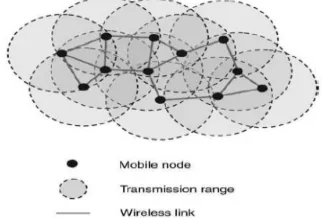
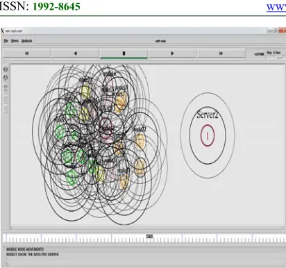
[image:1.612.112.273.610.719.2]MANETs are a cluster of nodes which interact without a specific access point or fixed infrastructures [1][2][3]. MANET networks are dynamic in environment and without a static topology. These ad-hoc networks have become popular due to the popularity of mobile devices. Wireless network communications are narrow by a node’s communication range and information is passed on in the network using a static topology, while the equivalent is achieved in a MANET using intermediate nodes. Figure.1 represents a MANET Topology.
Figure 1: MANET Topology.
MANET is a decentralized network using a dynamic formation of wireless links and not including the need for any cellular infrastructure. MANETs have found use in Military, Rescue operations, Conferences etc. These networks can pass on information in a single hop or use multiple hops. Nodes communicate with further nodes in the transmission range in a single hop MANET. Since MANETs infrastructure is not static, the nodes move freely.
1869 can send and receive information, reducing the presented bandwidth. MANETs can be created using different networks like Vehicular Ad hoc Network (VANET) or Body Area Network (BAN) or Wireless Sensor Network (WSN). Technologies like IEEE 802.11, Bluetooth and Ultra – Wide Band (UWB) can also be used for realizing MANETs. Mobile Ad hoc Network’s dynamic topology makes writing of routing algorithms challenging as nodes are mobile, changing the topology unexpectedly and thereby affecting the availability of routing paths. This paper proposes a new topology design called DCNRPT (Dynamic Configurable Network Routing Protocol based Topology) which segments nodes using clustering for a dynamic topology configuration based on the no. of nodes and their sites in a MANET.
2. RELATED STUDIES
MANET’s networking technology has inspired substantial research [4] as wireless applications need higher bandwidths and reliability in development. Wireless communications when combined with latest technology increases conventional broadcasting information into direct source-destination signal with cooperative communication [5] [6]. Spectral and power efficiency are regarded as a hopeful approach to network coverage [7] and cooperative protocol relay selection techniques [8]. Selection of proper relay transmission rate can maximize reliability [9]. MANET’s cooperative communication has made significant impact on the network topology and network topology control determine deployments. An apt topological network connectivity can optimize performances [10] [11]. MANET’s cooperative communication ability is a dynamic channel [12]. Compass Routing and FACE-1 algorithms were proposed in [11] that guaranteed delivery of information in greedy forwarding, in spite of local minimum phenomenon occurs. FACE -2 routing algorithm was proposed in [13] using the edging of the Gabriel Graph (CG) formed at every node. A probabilistic answer called Intermediate Node Forwarding (INF) using a Negative Acknowledgment (NAK) packet for providing feedback on dropped packets to the source was proposed in [14] A Geographic and Energy Aware Routing (GEAR) proposed in [15] to route a packet toward a region of interest. It worked well for small factions, but its efficiency dropped on larger areas of focus. A participating node’s unavailability either due to power shortage or signal strength can create gaps in a network. Gaps means Black holes
are shaped due to power exhaustion of the nodes. This results in a heavy resource conflict between neighboring nodes and thus limiting bandwidth or access [16]. Worm hole is one of the denials of service attack [17]. Sensor holes/gaps were determined theoretically with and an algorithm called BOUNDHOLE [18]. The study in [19] detected holes and map jammed regions in a antenna network by applying heuristics data like bit-error rates, to discriminate jamming from regular interference. Accordingly, a discrete stochastic optimization problems in topology control MANETs as the problem, and it is a stochastic approximation approach [20] can be solved using [21], which is to prove the optimal solution by converging iteratively to move towards a better solution analysis and simulation in the paper by the one of the advantages of iterative approaches that it dynamically reconfigure the network topology change can track mobile environment.
3. CLUSTERING
1870 Categories) based on similarity of a predefined property. Classical clustering dates back to the early 20th century, covering a wide spectrum like centric clustering, connectivity clustering, density clustering, etc. The results of clustering and cluster attributes like average element size, number of clusters, minimum or maximum size etc., generate knowledgeable interest. Many studies have evaluated and compared network clustering algorithms and their performances [28]. Hence, this examine work underlines the use of clustering in identifying and proposing a topology connectivity from a group of nodes for efficiency. Multiplicities of Traffic Patterns exist in wireless communications. Using Local Communication pattern, node information is divided amongstits neighbors and data is transmitted directly between nodes. In a Point-to-Point routing pattern, information is transmitted to another node from an arbitrarily chosen node (Wireless LAN)[29][30]. Compound node information is shared to a one base node in convergence pattern and helps data collection in wireless.
Figure 2: Wireless Traffic Patterns.
Intermediate nodes process information and the aggregation is passed on the base node in an Aggregation Traffic Pattern. The Divergence Traffic pattern sends a request or data from a base node to another sensor node. Figure.2 depicts a few traffic patterns used in wireless communications.
4. DYNAMICALLY CONFIGURABLE MANET TOPOLOGY
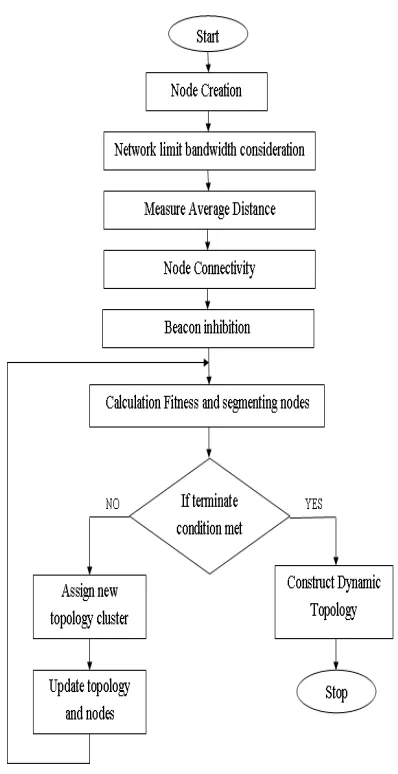
[image:3.612.93.295.365.615.2]The following methodology diagram for Figure 3. dynamically configurable manet topology to create a node.
Figure 3 : Methodology diagram for DCNRPT
PSEUDO Code
Set ns as new simulation
Define Data_Colors=RGB
namTract =out.nam
1871 global ns nf
flush-trace end
close $nf
Begin
exec out.nam end flush End
Begin node path
set n0 [$ns node] set n1 [$ns node] set n2 [$ns node] set n3 [$ns node]
duplex-link $n0 $n2 2Mb 10ms DropTail duplex-link $n1 $n2 2Mb 10ms DropTail duplex-link $n2 $n3 1.7Mb 20ms
DropTail
queue-limit $n2,$n3 = 10
duplex-link-op $n0 $n2 orient right-down duplex-link-op $n1 $n2 orient right-up duplex-link-op $n2 $n3 orient right
duplex-link-op $n2 $n3 queuePos 0.5
set sink [new Agent/TCPSink] attach-agent $n3 $sink connect $tcp $sink $tcp set fid_ 1 End
Begin schedule node as agent "$cbr start" = 0.1 "$ftp start" = 0.1 "$ftp stop" =4.0 "$cbr stop" = 4.5
$ns detach-agent $n0 $tcp ; detach-agent $n3 $sink"
$finish=0.5 End
Begin Run simulation
puts "CBR packet size = [$cbr set packet_size_]"
puts "CBR interval = [$cbr set interval_]" $ns run
End
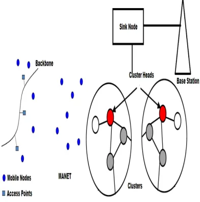
[image:4.612.323.519.234.432.2]Wireless routing techniques need improvements, due to energy constraints of a node. Optimal routing techniques can help in better utilization of the resources, thus improving the life time of a network. Topology of MANET after deployment decides on its maximized resource usage. The proposed topology, DCNRPT, attempts to identify shortest routing paths and configures MANET connections dynamically. Figure.4 depicts the DCNRPT Architecture,
Figure 4: DCNRPT Architecture.
1872
[image:5.612.235.515.69.320.2]
Figure 5: DCNRPT Requirements.
DCNRPT takes into account network limitations in the second step and the range of the wireless deployment is decided. Figure.6 depicts DCNRPT’s node creation.
Figure 6: DCNRPT Node Creation.
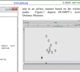
DCNRPT created nodes are then clustered for defining cluster heads in the wireless network and defines the parameters X,Y which denote the source and destination Ranges of a wireless. This is followed by defining the height of the wireless network. It then finds the average distance between nodes by using the Dijkstra’s Algorithm for construction of shortest routing paths dynamically
and in an ad-hoc manner based on the wireless nodes. Figure.7 depicts DCNRPT’s Active Distance Measure.
[image:5.612.98.367.73.329.2]
Figure 7: DCNRPT Active Distance Measure
Nodes are then grouped for connectivity using the previously calculated average distance measure. Transportation networks with many nodes rise in complexity and their comparisons become difficult. A node’s accessibility is not evident easily and measures and indices are needed to evaluate network efficiency. After nodes are created the average distances between the nodes are measured. DCNRPT’s active distance measures helps in its efficient topology proposals based on time. A network with higher active distance tends to be less linked and active distances are reduced for higher connectivity (Planar networks have larger active distances due to intermediary ends between two distant nodes). DCNRPT then finds the threshold of each neighborhood as a validation measure using the Beacon inhibition mechanism and given in eq.(1)
T ………. (1)
[image:5.612.91.300.415.604.2]1873 Figure 8: DCNRPT Node Connectivity Pattern.
The following DCNRPT (Dynamic Configurable Network Routing Protocol based Topology) algorithm is used to create the dynamic network topology for data points (nodes) in the proposed method using node energy.
DCNRPT Algorithm
Input : Set Maximum limit of X,Y from network land; Set Height coordinate system
Output : Create Dynamic Configurable Network Topology
/* Initialization*/
Step 1: Initialization of time T= 0 Step 2: For node= 1 to n do
Step 3: Randomly select the end point destination node
Step 4: Launch exploring point Step 5: End For
/* The exploring and reaches the destination*/ Step 6: Launch backward node
Step 7: For each backward node do Step 8: Track backward and exploring node Step 9: Update routing tables
/* Process data packet */ Step 10: Initialization time T=0
Step 11: Receive packets p from Media Access Control layer
Step 12: For each p do
Step 13: Select next node j among neighbor nodes Step 14: Update routing tables
Step 15: Processing data packet {delivery, forward or discard}
Step 16: End For
Step 17: Remove expired packet Receive new packet
Step 18: Compute network statistics Step 19: End For
DCNRPT Advantages: DCNRPT’s generated clustered pattern uses the threshold value based on eq. (1) for beacons. The use of beacon inhibition mechanism helps in the reduction of collisions and increases transmission efficiencies. Any node can emit multiple messages based on its threshold value. DCNRPT attempts to overcome issues in topological segmentation of other methods. Since it uses clustering, nearest nodes are identified to form cluster heads. The major advantage of using cluster heads is to reduce load on the sensing nodes. The traffic to the sink nodes are reduced by the cluster heads as they take charge of a set of sensor nodes. The information from these nodes are transmitted to the cluster heads which then forwards it to the sink nodes. DCNRPT’s clusters helps in better productivity. Moreover, since the messages that are flashed are dependent on the threshold values, the information flow within the network is optimized. The commonly used weight function, avoids the randomness problems of k-means clustering method. The performance of the proposed technique shows that it can work well even on complex networks. Since, DCNRPT is based on mutual information sharing between neighbors; it increases segmentation robustness and drives DCNRPT architecture towards a more rational topological/semantic map.
V. SIMULATION RESULTS AND ANALYSIS
1874 performance of the proposed DCNRPT routing protocol can be evaluated in the following performance metrics: packet transfer rate, performance, latency, and jitter.
Table 1 : Simulation parameters
Parameters Value
Simulation NS-2
MAC Protocol IEEE 802.11
Protocol Name DCNRPT, WCA
Mobility Model Random
Waypoint
No. of Nodes 100
Transmission Range 250meters
Size of Network 500m * 500m
Pause Time 25s
Hello Interval 5.0s
Simulation Duration 500 times
The following performance metrics to evaluate through networks simulation (NS2):
5.1 Packet Delivery Ratio
[image:7.612.313.529.337.486.2]The packet transfer relationship is computed by separating the no.of packets received by the destination by the number of packets initiated by the application layer of the source. Specify the packet failure rate, which limits the highest performance of the network. The better the transfer relationship, the more complete and correct the routing protocol.
Figure 9: Packet Delivery Ratio(%) Vs Mobility(m/s)
[image:7.612.313.524.589.717.2]In Figure.9 the proposed DCNRPT algorithm provides better performance compared to existing WCA algorithm and also increased packet delivery ratio with mobility is increased.
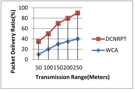
Figure 10: Packet Delivery Ratio(%) Vs Transmission Range(Meters).
In Figure.10 the proposed DCNRPT algorithm provides better performance compared to existing WCA algorithm and also increased packet delivery ratio with transmission range is increased.
0 20 40 60 80 100
5 10 15 20 25
Packet Delivery
Ratio(%)
Mobility(m/s)
DCNRPT
WCA
0 20 40 60 80 100
50 100150200250
Packet Delivery Ratio(%)
Transmission Range(Meters)
DCNRPT
WCA
0 20 40 60 80 100
20 40 60 80 100
Packet Delivery
Ratio(%)
No.of Nodes
DCNRPT
1875 Figure 11: Packet Delivery Ratio(%) Vs No.of
Nodes.
In Figure.11 the proposed DCNRPT algorithm provides better performance compared to existing WCA algorithm and also increased packet delivery ratio with number of node is increased.
5.2 Throughput
[image:8.612.91.302.310.448.2]The performance of the protocol can be defined as the percentage of packets received by the receiver between packets transmit by the source. It is the quantity of data per unit time passed from one to another over a communication link. Performance is calculated in bits per second and it is generally measured by kbps or mbps.
Figure 12: Throughput(kbps) Vs Mobility(m/s)
[image:8.612.314.524.484.621.2]In Figure. 12 the proposed DCNRPT algorithm provides better performance compared to existing algorithm WCA and also increased throughput with mobility is increased.
Figure 13: Throughput(kbps) Vs Transmission Range(Meters)
In Figure. 13 the proposed DCNRPT algorithm provides better performance compared to existing WCA algorithm and also increased throughput with transmission range is increased.
Figure 14: Throughput(kbps) Vs No.of Nodes
In Figure. 14 the proposed DCNRPT algorithm provides better performance compared to existing WCA algorithm and also increased throughput with number of node is increased.
5.3 Jitter
It is the time variation between the arrivals of the packet. The stability of the response of measurement algorithm to structural changes. It is the deviation of the ideal delay and caused by network congestion, sudden changes in network topology, or routing changes.
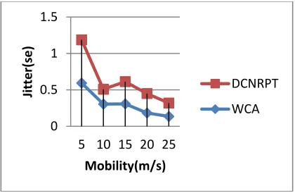
Figure 15: Jitter(sec) Vs Mobility(m/s).
In Figure.15 the proposed DCNRPT algorithm provides better performance compared to existing algorithm WCA and also increased jitter with mobility is increased
0 2000 4000 6000 8000
5 10 15 20 25
Throughpu
t(kbp
s)
Mobility(m/s)
DCNRPT
WCA
0 2000 4000 6000 8000 10000
50 100 150 200 250
Throughpu
t(kbp
s)
Transmission Range(Meters)
DCNRPT
WCA
0 2000 4000 6000 8000 10000
20 40 60 80 100
Through)pu
t(kb
ps
No. of Nodes
DCNRPT
WCA
0 0.5 1 1.5
5 10 15 20 25
Jitter(se)
Mobility(m/s)
DCNRPT
[image:8.612.89.299.542.684.2]1876 Figure 16: Jitter(sec) Vs Transmission
Range(Meters).
[image:9.612.90.300.344.487.2]In Figure.16 the proposed DCNRPT algorithm provides better performance compared to existing algorithm WCA and also increased jitter with transmission range is increased.
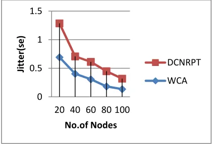
Figure 17: Jitter(sec) Vs No. of Nodes.
In Figure.17 the proposed DCNRPT algorithm provides better performance compared to existing algorithm WCA and also increased jitter with number of node is increased.
5.4 Delay
The end-to-end delay of a packet is the time at which the originating node generates the packet until it reaches the destination node. This is the time it taken packet to pass through the network. This time is expressed in seconds. Therefore, all network delays are known as packet-to-end delays, such as buffer queues and broadcast times. Sometimes this delay can be called a delay. Some applications are sensitive to packet delays because speech is a latency-sensitive application. Therefore,
voice requires a lower average delay in the network.
Figure 18: Delay time(sec) Vs Mobility(m/s).
[image:9.612.310.525.374.523.2]In Figure.18 the proposed DCNRPT algorithm provides better performance compared to existing WCA algorithm and also reduced delay time with mobility is increased.
Figure 19: Delay time(sec) Vs Transmission Range(Meters).
In Figure.19 the proposed DCNRPT algorithm provides better performance compared to existing WCA algorithm and also reduced delay time with transmission range is increased.
In Figure.20 the proposed DCNRPT algorithm provides better performance compared to existing WCA algorithm and also reduced delay time with number of node is increased.
0 0.5 1 1.5
50 100150200250
Jitter(se)
Transmission Range(Meters)
DCNRPT
WCA
0 0.5 1 1.5
20 40 60 80 100
Jitter(se)
No.of Nodes
DCNRPT
WCA
0 200 400 600 800 1000 1200
5 10 15 20 25
Delay time(sec)
Mobility(m/s)
WCA
DCNRPT
0 200 400 600 800 1000
50 100 150 200 250
Delay time(sec)
Transmission Range(Meters)
WCA
1877 Figure 20: Delay time(sec) Vs No. of Nodes.
VI. CONCLUSION
The implementation of MANET network maintenances is a difficult task suitable to the mobility of the nodes. This paper has proposed and demonstrated a topology generation approach that can adapt to changing mobile locations while maximizing speed, efficiency and be implemented in complex MANET networks. Analysis and results imply that DCNRPT algorithm used to better performances in the dynamically changing MANET networks compared to weighted clustering algorithm. It can be used as a base for future expansions in dynamically configurable topology designs for MANETs. Though simulated on NS2, it can be adapted to real time MANETs for increasing energy efficiency and speeds. It can be also concluded that DCNRPT is a viable technique that able to be applied to existing WCA in MANETs for upgrades and also improving packet delivery ratio, throughput, jitter and reduced delay time.
REFERENCES
[1] G. Jayakumar and G. Gopinath, “Ad hoc mobile wireless networks routing protocol — A review,” J. Comput. Sci., vol. 3, no. 8, pp. 574–582, 2007.
[2] S.Prabha, R.Yadav,”Differential Evolution for Mobile Ad Hoc Networks: A Review”, International Journal of Computersciences and Engineering, Vol.6, Iss.6, pp.1459-1467, 2018. [3] A.Tabesh and L.G.Frechette, “A low-power
stand-alone adaptive circuit for harvesting energy from a piezoelectric micropower generator,” IEEE Trans. Ind. Electron., vol. 57, no. 3, pp. 840–849, Mar. 2010.
[4] Jagrati Nagdiya, Shweta Yadav, Study of Various IP Auto-configuration Techniques, International Journal of Scientific &
Engineering Research, Vol. 4, Issue. 8, August-2013.
[5] Vishal Sharma, “Clustering and Energy Efficiency in Wireless Sensor Networks: A Study”, Vol.4, Iss.12, pp.78-82, 2016.
[6] L. Cottatellucci X. Master, E. G. Larsson, and A. Ribera, “Cooperative communications in wireless networks,” EURASIP J. Wireless Commun. Newt. vol. 20, 2009.
[7] A. Scaglione and Y. Hong, “Opportunistic large arrays: cooperative transmission in wireless multichip ad hoc networks to reach far distances,” IEEE Trans. Signal Process., vol. 51, no. 8, pp. 2082-2092, 2003.
[8] J.Laneman, D.Tse, and G. Wornell, “Cooperative diversity in wireless networks: efficient protocols and outage behavior,” IEEE Trans. Inf. Theory, vol. 50, no. 12, pp. 3062-3080, 2004.
[9] K. Woradit, T.Quek, W. Suwansantisuk, M. Win, L.Wuttisittikulkij, and H.Wymeersch, “Outage behavior of selective relaying schemes,” IEEE Trans. Wireless Commun., vol. 8, no. 8, pp. 3890-3895, 2009.
[10] Mrs.J.Vijayalakshmi and Dr.K.Prabu, “A Survey of Various Weighted Based Clustering algorithm in MANET”,International Journal of Data mining Techniques and Applications, Vol. 7, Iss.1, pp.146-153, june 2018..
[11]P. Santi, “Topology control in wireless ad hoc and sensor networks,” ACM Compute. Surveys, vol. 37, no. 2, pp. 164-194, 2005. [12]L. Tong, B. Sadler, and M. Dong,
“Pilot-assisted wireless transmissions: general model, design criteria, and signal processing,” IEEE Signal Process. Mag., vol. 21, no. 6, pp. 12-25, 2004.
[13]Sunil Pathak and Sonal Jain, “A Novel weight based clustering algorithm for routing in MANET”, Wireless Network, 22, pp.2695-2704, 2016.
[14]S. Douglas, D. Couto and R. Morris, "Location proxies and intermediate node forwarding for practical geographic forwarding," MIT Laboratory for Computer Science MIT-LCS-TR-824, 2001
[15]Y. Yu, R. Govindan and D. Estrin, "Geographical and Energy Aware Routing: A Recursive Data Dissemination Protocol for Wireless Sensor Networks," UCLA Computer Science Department UCLA/CSD-TR-01-0023, 2001.
[16]A. D. Wood and J. A. Stankovic, "Denial of service in sensor networks," IEEE Computer Magazine, vol. 35, pp. 48 - 56, 2002.
0 200 400 600 800 1000
20 40 60 80 100
Delay time(sec)
No. of Nodes
WCA
1878 [17]J.Vijayalakshmi and K.Prabu, ”Performance
Analysis of Clustering Schemes in MANETs”, International Conference on Intelligent Data Communication and Technologies and Internet of Things(ICICI)2018, pp.808-813, 2018. [18]Q. Fang, J. Gao and L. J. Guibas, "Locating
and Bypassing Routing Holes in Sensor Networks," in proceedings of IEEE INFOCOM, 2004.
[19]A. D. Wood, J. A. Stankovic and S. H. Son, "JAM: A Jammed-Area Mapping Service for Sensor Networks," in proceedings of 24th IEEE Real Time System Symposium (RTSS), 2003.
[20]H. Kushner, “Stochastic approximation: a survey,” Wiley Interdisciplinary Reviews: Computational Statistics, vol. 2, no. 1, pp. 87-96, 2010.
[21]V.Krishnamurthy and S. Chung, “Large-scale dynamical models and estimation for permeation in biological membrane ion channels,” Proc. IEEE, vol. 95, no. 5, pp. 853-880, 2007.
[22]Broido, A., and Claffy, K. “Internet topology: connectivity of IP graphs”, In SPIE International Symposium on Convergence of IT and Communication (August 2001), pp. 172–187.
[23]Gunes.M, and Sarac, K. “Resolving IP aliases in building trace route-based Internet maps. IEEE/ACM Transactions on Networking”, vol. 17, Issue. 6 , pp. 1738–1751, 2009.
[24]Kardes.H, OZ T, and Gunes, M. H. Cheleby: “A subnet-level Internet topology mapping system”, In International Conference on Communications Systems & Networks (COMSNETS) (2012).
[25]Tozal, M. E., and Sarac, K. “Estimating network layer subnet characteristics via statistical sampling”, In 11th international IFIP TC 6 conference on Networking – Volume Part I, IFIP’12, pp. 274–288, 2012.
[26]Mérindol.P, Donnet.B, Bonaventure.O, and Pansiot, J.-J. “On the impact of layer-2 on node degree distribution”, In ACM SIGCOMM Internet Measurement Conference (IMC) , pp. 179–191, 2010.
[27]LI. L, Alderson.D, Willinger.W, AND DOYLE.J, “A first-principles approach to understanding the Internet’s router-level topology”, In ACM SIGCOMM , pp. 3–14, 2004.
[28]Huang J, Sun H, Han J, Deng H, Sun Y, Liu Y. SHRINK: “A Structural Clustering Algorithm for Detecting Hierarchical Communities in
Networks”, In: Proceedings of the 19th ACM International Conference on Information and Knowledge Management. CIKM’10. New York NY, USA: ACM; p. 219–228, 2010. [29]S.Rajasekar and A.Subramani, “Performance
Analysis of Route Stability in MANET using Hidden Cluster Head (HCH) Algorithm”, International Journal of Control Theory and Applications, Vol. 10, no. 30, pp. 409-421, 2017.