Universal Journal of Electrical and Electronic Engineering 6(5): 373-382, 2019 http://www.hrpub.org DOI: 10.13189/ujeee.2019.060508
Study of Azimuth Angle and Elevation Angle Variations
of IRNSS/NavIC Signals
Sruthi Samyuktha Sathyana, Thangadurai N, Saribala Priyanka, Gutti Vaddi Navya, Gayathri K M*
Department of Electronics and Communication Engineering, School of Engineering and Technology, JAIN (Deemed-to-be University), Bangalore-562112, India
Received October16, 2019; Revised November 14, 2019; Accepted November 25, 2019
Copyright©2019 by authors, all rights reserved. Authors agree that this article remains permanently open access under the terms of the Creative Commons Attribution License 4.0 International License
Abstract
The IRNSS satellite network covers a large area of the India with 7 satellites, 3 geostationary and 4 that are geosynchronous. IRNSS signals are transmitted in the L5 and S-Bands. The L5 band frequencies range from 1164.45-1188.45 MHz and the S band frequencies range of 2483.5-2500 MHz. NavIC is the IRNSS satellite constellation network that can be employed to a variety of applications. The paper shows the analysis of the azimuth and elevation angle with respect to carrier to noise ratio. This study will be stepping stone for the collection of data using reflectometry. The different graphs were obtained and analyzed. Satellite tool kit is also used for the analysis of the elevation and azimuth angle.Keywords
RNSS, Elevation Angle, Azimuth Angle, TOWC1. INTRODUCTION
The Indian Regional Navigational Satellite System (IRNSS) is owned by the Government of India which is
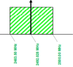
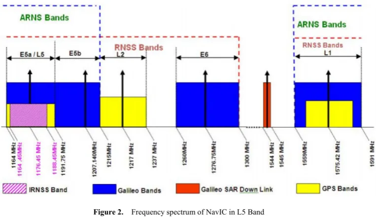
developed by Indian Space Research Organization (ISRO). This was renamed later as Navigation with Indian Constellation (NAVIC). This provides service of 1500km range around India. The IRNSS provides location and time to the IRNSS receiver [1,2]. The three segments in IRNSS are User segment, Control segment and Space segment. The space segment has 8 satellites where currently satellite 1’s clock is not working in which it failed in orbit to give position information. Four are in geostationary orbit (GEO) whereas 3 are in geosynchronous orbit (IGSO). These satellites are positioned in 340, 830, 1320,550 E and 111.750 E. The operation and maintenance of the IRNSS stations is done by the Ground segment. It consists of Data uploading stations, Master control stations and Base stations. The User segment consists of antennas and receivers to receive the IRNSS signals. Other than IRNSS signals it can also receive Galileo, GPS and GLONASS signals. The bandwidth in which the ISRO has filed is 24MHz in L5 Band (1164.45 – 1188.45 MHz) and 16.5 MHz in S1 Band (2483.5-2500 MHz) in which IRNSS receiver works and the frequency spectrum shown in Figure 1 and Figure 2 [4].
[image:1.595.303.433.575.693.2]Figure 2. Frequency spectrum of NavIC in L5 Band
Figure 3. IRNSS User Receiver
Figure 3 shows the representation flow of NavIC user receiver which follows: LNA,RF Front End, Correlators and demodulators, Navigation Processor and User Interface. This can receive both IRNSS and GPS data [14]. It has separate LNA for L5 and S1 band where the gain is 31 dB and 30 dB with corresponding noise figure is 0.9 dB for both. This receiver can operate in both modes i.e., dual frequency or single frequency. The services offered by the user receiver and the antenna are Standard Positioning Service (SPS) which is a free of cost service provided to the user and the Restricted Service (RS) which provides to authorized users. CDMA (Code Division Multiple Access) and BPSK (Binary Phase Shift Keying) modulation is used by the SPS signal. The navigation processor processes the navigation solution computation and the user interface interfaces the external device [3,13].
2. Azimuth and Elevation Angles
When the apparent position of a satellite in an orbit is to be determined relative to a point of observation, we need angles namely Azimuth and Elevation. These together are the antenna look angles [5]. Information needed for calculating the look angles are: latitude and longitude of the earth station and the satellite orbital position. The
azimuth and elevation angle settings of its antenna must be known to the earth station to communicate with the satellite [15, 16].
• Azimuth angle: It is the angle between a satellite and the North which is measured clockwise around the observer's (antennas) horizon or earth station’s horizontal plane, in general referenced north (0°) or to south (180°) clockwise.
• Angle of Elevation (EL): Vertical angle between the travelling direction from the earth station antenna to the satellite and the horizontal plane which is the earth’s horizon [6].
• In non-geostationary orbits the measures of these angles vary while for geostationary orbits these angles remain the same since satellites in GEO are in sync with earth’s rotation and seem stationary
.
[image:2.595.116.498.84.307.2]Universal Journal of Electrical and Electronic Engineering 6(5): 373-382, 2019 375
GPS of The United States, GLONASS of Russia, GALILEO of Europe and BEIDOU of China[7], additionally there are regional navigation systems which are QZSS of Japan and India’s very own IRNSS- use extremely accurate Rubidium or Cesium stable atomic clocks, with error probability of 1 second in every hundred million years, while receivers back on earth have crystal oscillators for providing time, these are chosen for economic reasons and are not synchronized with on board atomic clocks of the navigational satellites. This asynchronization reflects in calculated position and range. There are many other factors that cause delays and errors: ionospheric delay, tropospheric delay and multipath error [9]. The Distance commuted is known as the product of speed and time taken for travel, here the distance between satellite and receiver is determined by multiplying the time taken for the signal to reach the receiver from the transmitter satellite with the speed of light [10].
3. Data Collection
Data used for this analysis was collected on October 12th 2018 at JAIN GLOBAL CAMPUS’s CRICKET GROUND. Two receivers namely, A_37 and A_38 are used. The arrangement is such that the receivers were 30 meters apart, facing each other. There are four cases of this survey based on the direction at which the receivers were placed ((i) North and South, (ii) East and West) and
depending on each of the receivers being static and dynamic. The dynamic receiver was moved towards the static receiver and readings were taken simultaneously. Throughout the survey we were able to observe variations in elevation and azimuth angles with respect to its TOWC of all 7 functional IRNSS satellites, using this information various graphs are plotted [11,12].
4. Elevation and Azimuth Angle
Variations
The following are basic graphs obtained by the navigational data received by A_37 and A_38 receivers. Parameters TOWC, elevation and azimuth angles are used for plotting the graphs.
4.1. Case 1
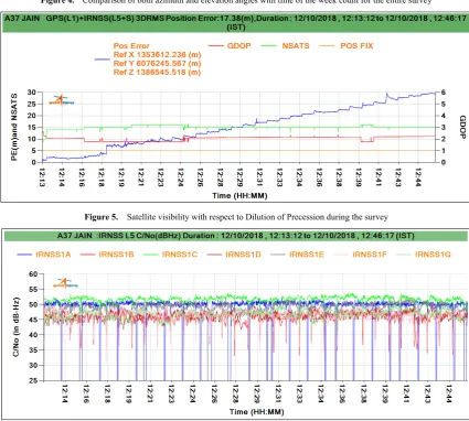
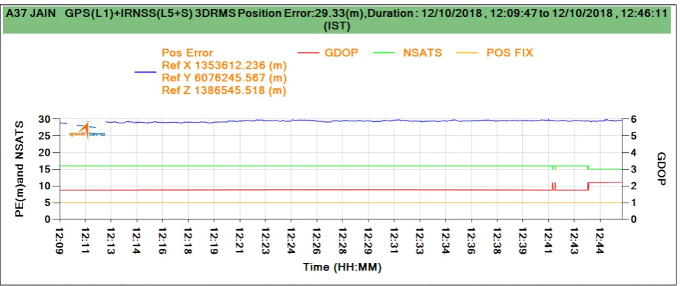
Receiver A_37 is dynamic and receiver A_38 is static. Receivers were 30 meters apart facing each other in north and south direction. The dynamic receiver A_37 was moved towards the static A_38 and readings were taken accordingly (Figure 4 (a) and (b)) and the variation of satellite visibility during the survey period shown in Figure 5. Figure 6 shows the carrier to noise variation of all IRNSS satellites during the survey. It is observed that the variations are below 25 dBHz represents the distractions during receiving the signals.
(b) A_38 receiver
Figure 4. Comparison of both azimuth and elevation angles with time of the week count for the entire survey
Figure 5. Satellite visibility with respect to Dilution of Precession during the survey
[image:4.595.72.523.81.342.2] [image:4.595.83.509.361.743.2]Universal Journal of Electrical and Electronic Engineering 6(5): 373-382, 2019 377
4.2. Case 2
In this set of survey, receiver A_37 is static whereas A_38 is dynamic; again facing towards each other at north and south directions. Here receiver A_38 is moved towards A_37 and the readings are taken accordingly (Figure 7(a) and (b)). Figure 8 shows the carrier to noise variation of all IRNSS satellites during case 2 survey.
[image:5.595.65.535.153.348.2](a) A_37 receiver (b) A_38 receiver
Figure 7. Plot for elevation and azimuth angles with respect to TOWC of receiver
Figure 8. IRNSS L5 band C/N0 during the survey when A38 is in static condition
4.3. Case 3
[image:5.595.59.539.376.577.2]Figure 9. Plot of Azimuth and Elevation vs C/No
Figure 10. C/No v/s Elevation angle
Figure 9 shows the plot between the Azimuth, Elevation angle and Carrier to noise ratio. We can observe that there are drops in C/No ratio with respect to elevation and azimuth angle. When the azimuth angle is at 120.255478 degree the C/No is zero because at that particular angle the carrier cannot track the channel and hence the reject clock varies randomly and the lock time will reset to zero and starts counts. The same holds good for the elevation angle. This can also be observed in Figure 10. Where the satellite is visible but still, we could not able to track the elevation and azimuth angle of a particular satellite.
[image:6.595.73.526.78.450.2] [image:6.595.61.539.554.728.2]Universal Journal of Electrical and Electronic Engineering 6(5): 373-382, 2019 379
Figure 11. Shows the plots of elevation and azimuth angle with respect to TOWC. Here we can observe that if few places the angle is dropping to zero. Even though the visiblititty of the satellite is there but the azimuth and elevation anale cannot be retrived because of issues in tracking the satellite which make the reject clock to vary abruptly and the lock time will restart.
4.4. Case 4
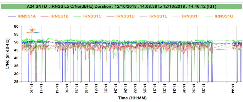
Here the receivers are facing towards each other positioned in east and west directions. In this case receiver A_37 is dynamic and A_38 is static which means that A_37 is moved from its position towards A_38. Following are graphs obtained from the readings taken (Figure 12) and the variation of satellite visibility during the survey period shown in Figure 13. Figure 14 shows the carrier to noise variation of all IRNSS satellites during the survey. It is observed that the variations are below 25 dBHz represents the distractions during receiving the signals.
Figure 12. Graph plotted for both azimuth and elevation angles of A_37 and A_38 with respect to its TOWC
[image:7.595.61.539.234.401.2] [image:7.595.58.543.425.629.2]Figure 14. IRNSS L5 band C/N0 during the survey when A37 is in static condition
5. Elevation and Azimuth Angle v/s Time and Distance
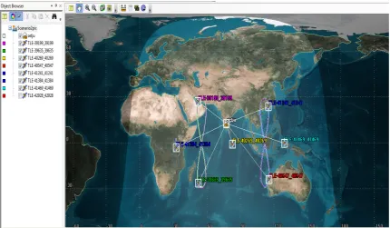
The below graphs are obtained with the help of satellite tool kit. They are comparisons of elevation and azimuth angles of all the seven functional satellites IRNSS-1B, IRNSS-1C, IRNSS-1D, IRNSS-1E, IRNSS-1F, IRNSS-1G and IRNSS-1I, whereas IRNSS-1A and IRNSS-1H aren’t functional. The purpose of using STK is to simulate the altitude and position of both GPS and IRNSS satellites in accordance with user location. Speed, angle of satellite movement, visibility of satellites, elevation and azimuth angle are determined using time and receiver as their reference [1,5,8]. The latitude and longitude values are entered by the user manually. The two line elements (TLE) format is used to feed the data of IRNSS and GPS satellite into the STK platform. TLEs can describe the trajectories only of earth orbiting objects. “.tle” files which are used to map, track, examine and understand the satellite movement and behaviour are generated by ‘CELESTRAK’ with the receiver information given by the user. Path of the seven functional satellites of IRNSS are shown in fig. 15. The figure of ‘8’ path of Geo synchronous satellites(1B, 1D, 1E, 1I) is clearly visible; which is shown in the Figure 15, it shows the visibiity of all the seven satellites in a 2 dimensional view.
[image:8.595.69.526.83.265.2] [image:8.595.83.514.470.721.2]Universal Journal of Electrical and Electronic Engineering 6(5): 373-382, 2019 381
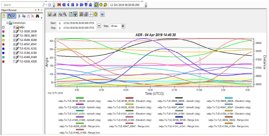
The start and stop considered for this graph is 12/10/2018-6:30AM and 13/10/2018- 6:30AM, respectively. There are 3 parameters which are used to plot the graph. They are time, angle and distance. The graph describes the variations in angle and distance over a particular time period. We are analyzing the graph for a fixed duration of 24 hrs. The start time is 12th October at 6:30a.m to 13 October 6:30a.m, with a step of 60 seconds. In Figure 16 graph the elevation angle and azimuth angle variations are clearly visible. From Table 1 it can be observed that the minor variation in the positional values i.e., latitude, longitude and altitude when compared with IRNSS and GPS receivers during the survey.
[image:9.595.70.527.158.389.2]Figure 16. Angle (Elevation and azimuth angle) versus time versus distane graph of IRNSS satellites
Table 1. Positional comparison between IRNSS and GPS during survey
NavIC/ IRNSS GPS
TOWC (s) Latitude (deg) Longitude (deg) Altitude (m) Latitude (deg) Longitude (deg) Altitude (m)
456210 12.6385 77.4412 616.0310 12.6383 77.4413 615.8921 456211 12.6385 77.4412 616.0528 12.6383 77.4413 615.9574 456212 12.6385 77.4412 615.3750 12.6383 77.4413 615.9575 456213 12.6385 77.4412 615.0501 12.6383 77.4413 616.1058 456214 12.6385 77.4412 615.0161 12.6383 77.4413 616.6309 456215 12.6385 77.4412 615.3763 12.6383 77.4413 616.4206 456216 12.6385 77.4412 615.5405 12.6383 77.4413 616.1795 456217 12.6385 77.4412 615.3326 12.6383 77.4413 616.2107 456218 12.6385 77.4412 616.3370 12.6383 77.4413 615.9951 456219 12.6385 77.4412 615.9829 12.6383 77.4413 615.7548
6. Conclusion and Future Scope
The IRNSS satellite network covers a large area of the India with 7 satellites, 3 geostationary and 4 that are geosynchronous. IRNSS signals are transmitted in the L5 and S-Bands. The L5 band frequencies range from 1164.45-1188.45 MHz and the S band frequencies range from 2483.5-2500 MHz. NavIC is the IRNSS satellite constellation network that can be employed to a variety of
[image:9.595.122.475.428.624.2]collect the data in the ground station.
Acknowledgements
Authors thank Space Applications Centre - Indian Space Research Organization (SAC-ISRO) for providing IRNSS receiver and encouraging us to work on navigation studies. Authors also thank Dr G. Raju, Professor, JAIN (Deemed-to-be University), Bengaluru for his constant support to complete this work successfully. The authors acknowledge the necessary infrastructure and supporting facility provided by JAIN (Deemed-to-be University).
REFERENCES
[1] A.K. Sharma, O.B. Gurav, Anindya Bose, H.P. Gaikwad, G.A. Chavan, Atanu Santra, S.S. Kamble, R.S. Vhatkar, “Potential of IRNSS/NavIC L5 signals for ionospheric studies”, Advances in Space Research, Vol. 63, Iss. 10, pp.3131 – 3138, 2019.
[2] Abhishek Rawat, Jatin Savaliya and Dwarkesh Chhabhaya, “Field Trial of IRNSS Receiver”, Microwave and Optical Technology Letters, Vol. 61, Iss.5, pp.1149 – 1153, 2019. [3] David Olivera Mezquita, “Satellite Tracking Through the
Analysis of Radiation Patterns”, pp. 1-5, 2011.
[4] http://www.sattvengg.com/2013/10/azimuth-and-elevation-angle-antenna.html
[5] https://gssc.esa.int/navipedia/index.php/NAVIC
[6] Joshi, Prashant and Dutta, Maitreyee and Bansal, Vivek, “Precise Positioning at Indian Region With Multi-Constellation GNSS Receiver SP80”, International Journal of Advanced Studies of Scientific Research, Vol. 3, Iss. 8, pp. 1-7, 2018.
[7] K. M. Gayathri, N. Thangadurai and M. P. Vasudha, Positioning and signal strength Analysis of IRNSS and GPS receiver in plain terrain along with foliage loss, Current Science, Vol. 112, No. 8, 25 April 2017.
[8] Kiran B , Raghu N , Manjunatha K N , Raghavendra Kumar M “Tracking And Analysis Of Three IRNSS Satellites by Using Satellite Tool Kit”, International Journal of Advance Research and Innovative Ideas in Education, Vol. 1, Iss. 5, 2016.
[9] Lasisi Salami Lawal, Chris R Chatwin, “Review of GNSS and Augmentation Systems”, Journal of Electrical And Electronics Engineering, Vol.5, Iss. 3, pp. 1-21, 2019. [10]Mehul V. Desai and Shweta N. Shah, “Estimation of
ionospheric delay of NavIC/IRNSS signals using the Taylor Series Expansion, Journal of Space Weather Space Climate, Vol. 9, No. A23, pp. 1-17, 2019.
[11]Mohmad Umair Bagali, Naveen Kumar Reddy, Ryan Dias, Dr. Thangadurai N “The Positioning and Navigation System on Latitude and Longitude Map using IRNSS User Receiver” Proc. of IEEE International Conference on
Advanced Communication Control and Computing Technologies, pp.122-127, 2016.
[12]Nain, S. and Joshi, M., "Comparison of Indian Regional Navigation Satellite System (IRNSS) and Global Positioning System (GPS) in Vehicle Tracking Application," SAE Technical Paper, Vol.28, pp. 1-4, 2019. [13]Varsh H.S, Shreyanka B Chougule, Dr. N.V Vighnesam, Dr.
Sudha K, “Analysis of Pseudo-range Measurements Observed in NavIC Receiver, Journal of Engineering Research and Application, Vol. 8, Iss. 12, pp 43-46, 2008. [14]Xu G., “GPS data processing with equivalent observation
equations”, GPS Solutions, Vol. 6, Iss.2, pp. 28-33, 2002. [15]Gayathri K M, Dr. Thangadurai N, Vasudha M P,
“Performance Analysis of IRNSS Receiver Signal Strength and Accuracy on a Moving Vehicle” Proc. of IEEE International Conference on Advanced Communication Control and Computing Technologies, Ramanathapuram, pp.724-731, 2016.