© 2017, IRJET | Impact Factor value: 6.171 | ISO 9001:2008 Certified Journal | Page 370
EFFECT OF HEAT INPUT AND SHIELDING GAS ON MICROSTRUCTURE
AND MECHANICAL PROPERTIES OF AUSTENITIC STAINLESS STEEL
304L
E. S. Mosa
1, M. A. Morsy
2, A. Atlam
11
Al Azhar University, Faculty of Engineering, Mining and Petroleum Engineering Department.
2Central Metallurgical Research and Development Institute (CMRDI) Egypt.
---***---Abstract -
This work investigates the effects of heat input
and shielding gas composition on microstructure, ferrite number, ultimate tensile strength, hardness, and impact of austenitic stainless steels 304L. The shielding gases used in this study are pure Argon and mixture of 98% Argon (Ar) and 2% Nitrogen (N). Gas tungsten arc welding (GTAW) process was applied to weld joints. The results of the present work showed that the shielding gas composition has a significant effect on microstructure, ultimate tensile strength and hardness. Microstructure revealed changing in solidification structure from ferrite to austenite when used shielding gas 98% Ar and 2% N and revealed when heat input increased the dendrite size and inter-dendritic spacing in the weld metal also increase. The ferrite number decreased with increasing the heat input and using mixture of 98 % Ar and 2 % N. Transverse tensile test revealed that the average ultimate tensile strength (UTS) values increased with decreasing the heat input, using mixture of 98 % argon and 2 % nitrogen as shielding gas. furthermore Hardness values increased with decreasing of heat input and using shielding gas of 98 % Ar and 2% N.
Key Words: Heat input, Shielding gas, austenitic Stainless steel 304L
1. INTRODUCTION
Stainless steels are an important class of engineering materials that have been used widely in a variety of industries and environments. Austenitic stainless steels have been used widely by the fabrication industry owing to their excellent high temperature and corrosion resistance properties. Some of the typical applications of these steels include their use as nuclear structural material for reactor coolant piping, valve bodies, vessel internals, chemical and process industries, dairy industries, petrochemical industries etc. Welding is an important fabrication technique for stainless steels, and numerous specifications, papers, handbooks, and other guidelines have been published over the past 75 years that provide insight into the techniques and precautions needed to weld these materials successfully [1]. Austenitic stainless steels, such as the type 300 series, are used in various types of plant because of their excellent corrosion resistance, good mechanical strength at high
temperature, and high fracture toughness at low temperature [2]. Type 304 SS is extensively used in industries due to its superior low temperature toughness and corrosion resistance [3]. American Iron and Steel Institute (AISI) type 304 is the foundation of 300 series austenitic stainless steels is by far the oldest, largest and most important group in the stainless steel range [4].
Gas tungsten arc welding (GTAW) is the most important joining technique in almost all types of manufacturing industries. GTAW is suitable for welding thin materials when good quality and surface finish are required [5]. Gas Tungsten Arc Welding (GTAW), also known as tungsten inert gas (TIG) welding is a process that produces an electric arc maintained between a non-consumable tungsten electrode and the part to be welded [6]. Nitrogen is a very strong austenitic former, adding small amounts of nitrogen into the argon shielding gas during welding will dramatically decrease the amount of delta ferrite in an austenitic stainless steel weld metal [7].
© 2017, IRJET | Impact Factor value: 6.171 | ISO 9001:2008 Certified Journal | Page 371
2. Experimental Work
2.1 Base metal and filler metal
The base metal used in this investigation is austenitic stainless steel grade type 304L which has specified minimum yield strength 205 MPa and ultimate tensile strength 515 MPa[14], and its chemical composition and microstructure are shown in table 1 and fig 1 respectively. The filler wire used in this investigation is ER308L which is solid wire of the specification and classification in ASME SFA 5.9[15], and its chemical composition is shown in table 1.
2.1 Welding Procedure
In the present work single V-groove design was used. Before welding all the edges were thoroughly cleaned mechanically and chemically in order to avoid any source of contamination like rust, scale, dust, oil, moisture etc. After tacking the plates together the first weld pass was given using GTAW process with welding procedures as mentioned in Table 2 and prior to giving of second pass an interpass temperature of around 150oC was maintained. No preheat or post heat treatment was given to the specimens. During this work six samples are welded using different heat input and shielding gases.
Fig.1 Microstructure of base metal, AISI 304L.
Table 1 chemical composition of austenitic stainless steel 304L and filler metal ER 308L
2.3 Specimen sampling
The specimens for tensile testing, microstructure studies were taken from the weld pads as schematically illustrated in Fig 2
.
[image:2.595.310.570.60.191.2]
Fig.2 schematic illustration of the specimen sample from the weld pads
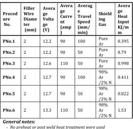
Table 2 Welding Procedures
Proced ure No.
Filler Wire Diame ter (mm)
Avera ge Volta ge (V)
Avera ge Curre nt (amp )
Averag e Travel Speed (mm/ min)
Shield ing Gas
Avera ge Heat Input KJ/m m
PNo.1 2 12.2 90 100 Pure Ar 0.395
PNo.2 2 12.2 90 50 Pure Ar 0.79
PNo.3 2 12.6 110 50 Pure Ar 0.998
PNo.4 2 12.7 90 100 98% Ar
/2% N 0.411
PNo.5 2 12.7 90 50 98% Ar
/2% N 0.822
PNo.6 2 13.3 110 50 98% Ar
/2% N 1.53
General notes:
- No preheat or post weld heat treatment were used - Inter pass temperature max (150 oC)
- Calculation of heat input is bases on arc efficiency % 60 as
Where: Q is heat input, V is volt, I is welding current and S is travel speed
2.4 Metallography
In order to observe the microstructure changes that take place during welding, the test specimen was cut for cross sections, mounted and grind with emery paper to a 1200 grit size. A polishing machine was then used to polish the sample to a mirror finish before etching After polishing process, the sample was then electrolytically etched using 10% oxalic acid etching solution and 90% distilled water. A power supply applied approximately 1 Amp and 5 Volts for about 60 seconds to etch each sample. Standard polishing procedures were used for general microstructure observations [16]. Microstructures of weld metal, under different heat input and shielding gas were viewed and captured with an optical microscope coupled with animage analyzing software.
Mate
rial C %
M n %
Si
% S % P % Cr % Ni % Cu% Fe %
Base
metal 0.03 1.61 0.4 0.002 0.022 18.04 8.17 -- Balance
Filler
[image:2.595.303.566.253.507.2] [image:2.595.47.282.396.523.2]© 2017, IRJET | Impact Factor value: 6.171 | ISO 9001:2008 Certified Journal | Page 372
2.5 Ferrite Number
Ferrite Number (FN) is termed to measure the delta-ferrite content. The amount of ferrite is measured magnetically according to AWS A4.2 standard [17]. A ferrite-scope was used to measure the ferrite number of the weld metal.
2.5 Tensile Tests and Ductility
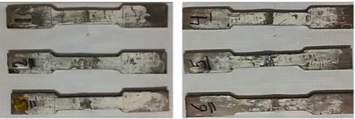
The tensile test was carried out for determining the ultimate tensile strength and ductility of the welded joint. The test specimens for tensile test were cut from the welded test piece perpendicularly to the welding direction .The shape and dimensions of the tensile test specimen which was according to ASME (IX) [18] or ASTEM E08 as shown in fig 3, and also the specimens prepared for tensile test as shown in fig 4.
Fig.3 Dimensions of reduced section tensile test specimen
Fig.4 The samples prepared for tensile test
2.7 Hardness Test
The Vickers hardness test using (HMV microhardness tester- Shimadzu Japan) was carried out for determining the hardness values of weld metal and heat affected zone (HAZ) for each welded joint of test pieces. The test specimens for hardness test were cut from the welded test piece perpendicularly to the welding direction
2.8 Impact Test
The impact toughness tests were conducted using standard specimens of 5*10*55 mm. The tests were carried out at ambient temperature, (-85 and -196°C). Liquefied nitrogen was used to obtain (-196oC) however dilute the liquefied nitrogen with acetone was used to get (-85 oC). The specimens needed for impact toughness test were cut
perpendicularly to the welding direction and with dimensions in accordance with ASME SA370 [19].
3. Results and discussion
3.1 Metallographic studies
3.1.1 Effect of Heat Input
The effect of heat input was studied by procedures PNo.1, PNo.2 and PNo.3 where three levels of heat input (0.395, 0.79 and 0.998 Kj/mm respectively) were produced as shown in Table 2. As well known, microstructure, microhardness, ferrite number, ultimate tensile strength, hardness and impact were affected by heat input .
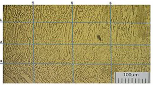
Microstructure (dendrite) of weld metal for procedures PNo.1, PNo.2 and PNo.3 are demonstrated in Fig 5, Fig 6 and Fig 7 respectively.
From the obtained micrographs, it is obvious that the microstructures of 304L stainless steel weld metals are completely different from that of the base metal (fig 1). All weld metals have dendrite structure (ferrite and austenite) phases [20, 21], but the base metal is fully austenitic structure fig.1.
Measurements of dendrite cells or arm spacing are accomplished in the same manner as grain size measurements [22], that is, usually by the intercept method. A complete procedure for measuring the size of non-equiaxed grains or dendrites is described in ASTM E112[23]; measured grain sizes usually are expressed in the number of grains per square millimeter, mean area per grain, or mean diameter per grain.
In the present investigation, because of the shape of dendrites which is completely non equiaxed, six lines are used to calculate number of intercepts; three of them are horizontal and the others are vertical; like grids. The results are represented in Fig.5, Fig.6 and Fig. 7 and listed in Table 3 for PNo.1 , PNo.2 and PNo.3 respectively. The results show that a relatively difference between sizes of dendrites is noted; ASTM number of dendrites for these procedures are from 9.9 to 11.5. Therefore, dendrites of ER308 deposits have tendency to coarsening within the implemented Heat input range (from 0.395 to 0.998 Kj/mm).
[image:3.595.39.291.300.373.2] [image:3.595.40.294.415.500.2]© 2017, IRJET | Impact Factor value: 6.171 | ISO 9001:2008 Certified Journal | Page 373
Fig.5 Dendritic structure of WM of PNo.1 (0.395 Kj/mm, pure argon).
Fig.6 Dendritic structure of WM of PNo.2 (0.79 Kj/mm, pure argon).
Fig.7 Dendritic structure of WM of PNo.3 (0.998 Kj/mm, pure argon).
Table 3 ASTM Number
P.No P.No 1 P.No 2 P.No 3
ASTM Number 11.5 10.4 9.9
Notes: Average ASTM number = -3.3 + 6.65 log (PL)
Where: PL is Number of intercepts per unit length multiplied by
magnification
3.1.2 Effect of Heat Shielding Gases
[image:4.595.40.283.59.209.2]Measurements of dendritic size are shown in Fig.8, Fig.9 and Fig.10 and the calculated ASTM numbers are listed in Table 4. These tables also demonstrate that the power of nitrogen on coarsening of dendrites increases with increasing heat input where more nitrogen was dissolved in weld metal [1]
when compared with dendrite size of PNo.1, 2 and 3 which welded using pure argon with PNo.4, 5 and 6 which was welded using mixture of 98% Ar and 2% N, the ASTM numbers of PNo.1, 2 and 3 are 11.5, 10.4 and 9.9 respectively while PNo.4, 5 and 6 are 10.7, 10.1 and 9.1 respectively the difference in dendrite sizes could be attributed to the nitrogen having small effect of increasing heat input and the nitrogen dissolved interstitially in the austenite [1].
[image:4.595.309.562.183.323.2]Fig.8 Dendritic structure of WM of PNo.4 (0.411 Kj/mm, 2%N/98%Ar).
Table 4 ASTM Number
P.No P.No 4 P.No 5 P.No 6
ASTM Number 10.7 10.1 9.1
Fig.9 Dendritic structure of WM of PNo.5 (0.822 Kj/mm, 2%N/98%Ar).
[image:4.595.41.289.300.547.2] [image:4.595.313.559.373.568.2] [image:4.595.312.558.612.749.2]© 2017, IRJET | Impact Factor value: 6.171 | ISO 9001:2008 Certified Journal | Page 374
3.2 Ferrite Number
Most austenitic stainless steel weld is designed to solidify to give primary ferrite and secondary austenite to minimize the occurrence of hot cracks. This solidification mode is known as the ferritic-austenitic solidification mode [22].
For PNo.1, PNo.2 and PNo.3, the ferrite number (FN) measurements are given in Fig.11 The results show that ferrite content in austenite is relatively reduced with increasing heat input. This could be attributed to the slow cooling rate which accompanied with high heat input giving more chance of ferrite to austenite transformation [24]. With increasing cooling (low heat input) the solid state transformation is suppressed and the ferrite content increases.
Ferrite number (FN) measurements for PNo.4, PNo.5 and PNo.6 reveals decreasing than PNo.1, PNo.2 and PNo.3. The comparison shows that using 2%N in shielding gas leads to the reduction in FN by about 40%. Many researches [1, 25, 26] emphasized this fact; they reported that the presence of nitrogen in weld metal significantly influences both the mode of solidification and the quantity of ferrite retained in the room temperature. They also showed that nitrogen is substituting for nickel as an austenite stabilizer [7].
In spite of ferrite is beneficial in avoiding solidification cracking, ferrite can be deleterious of weld ductility. Also ferrite can cause sigma phase formation which limits the usage of austenite weldment in high temperature applications and corroded environments. The recommended ferrite number in stainless steel ranged from 5 to 10 [10, 11], so PN.1 (FN 11.2) should be rejected to avoiding formation of sigma phase when using in high temperature application.
The powerful austenitizing effect of nitrogen (30 times greater than that of nickel) tends to suppress primary ferrite solidification and promote the primary solidification of austenite. DeLong constitutional diagram [27, 28, 29] is constructed depending on chromium (ferrite formers) and nickel (austenite formers) equivalents as the following equations:
Chromium equivalent = %Cr+%Mo+1.5(%Si)+ 0.5(%Cb) Nickel equivalent = %Ni + 30(%C) + 0.5(%Mn) + 30(%N)
Fig.11 Comparison between FN of welding procedures using shielding gas pure and 2% N/ 98%Ar.
3.2 Transverse Tensile Test and Ductility
Ultimate tensile strength and ductility were used to evaluate the effect of increasing heat input. these results are illustrated in Fig 12 for the investigated conditions. Average ultimate tensile strength values of weld metal for PNo.1, PNo.2 and PNo.3 are 613, 588 and 570 MPa respectively; however ductility values are 35.3, 37.3 and 38.4 % respectively. The results show that both ultimate tensile strength and ductility are slightly affected with increase the heat input. In spite of ultimate tensile strength is slightly affected but it can be attributed to the formation of delta ferrite in austenite and smallness dendrite size which give high ASTM number for dendrite [30].
The ultimate tensile strength results of PNo.4, PNo.5 and PNo.6 shows that nitrogen in shielding gas increases the ultimate tensile strength by about 40MPa higher than that for PNo.1, PNo.2 and PNo.3. (welded pure argon as shielding gas).
The results of ductility are demonstrating that the presence of nitrogen lowers ductility by 6 % as in Fig.13. It is also noted that the presence of nitrogen is more effective for PNo 4, where the increase in strength is about 55 MPa. ductility reduced by 8 %, and ferrite number 40%. this could be attributed to nitrogen absorbed during welding resulted in interstitial solid solution strengthen as the carbon [1,5].
Fig.12 Comparison between ultimate tensile strength of welding procedures using shielding gas pure Ar and
2%N/98%Ar
© 2017, IRJET | Impact Factor value: 6.171 | ISO 9001:2008 Certified Journal | Page 375
3.3 Microhardness Test
Micro hardness measurements were taken in two directions firstly in the transverse direction perpendicular to the base plate surface and secondly, in the longitudinal direction parallel to the base plate surface. Micro hardness of different zones of the weldments was measured using Vickers’s micro hardness testing machine.
The results represent that the hardness values are ranged from 167 to 212 HV which reflects the austenitic matrix of BM, HAZ, and WM. Average hardness of the HAZ is larger than the BM and WM. Higher hardness in HAZ is attributed to the occurrence of recrystallization and rapidly cooled during and after welding which result in coarse and fine grain structure Fig. 14. Comparison between the three levels of heat input shows that PNo.1 has a maximum hardness values of WM; about 186 HV which welded using lowheat input, this could attributed to smaller dendrite sizes and lesser inter- dendrite spacing of weld metal which give larger ASTM Number for grains [2].
[image:6.595.303.572.80.221.2]Nitrogen is a strong solid-solution strengthener. Nitrogen occupies interstitial sites and expands the lattice in a manner similar to carbon [1]. Unlike high carbon contents, high nitrogen contents do not result in sensitization problems. The hardness across BM, HAZ, and WM for PNo.4, PNo.5 and PNo.6 are plotted in Fig.15. The results represent that for the three procedures, hardness values ranged from 184 to 212 HV and the maximum of WM is about 200 HV and possessed for PNo.4. when compared with hardness values of PNo.1, 2 and 3 which were welded using pure argon with PNo.4, 5 and 6 which were welded using mixture of 98% argon and 2% nitrogen, the maximum hardness of weld metal for PNo.1, 2 and 3 are 186, 176 and 170 HV respectively while for PNo.4, 5 and 6 are 200, 194 and 189 respectively the difference in hardness values are small that could attributed to the nitrogen absorbed during welding resulted in interstitial sold solution strengthen as the carbon [5]
Fig. 14 Hardness values for PNo.1 (0.395 Kj/mm), PNo.2 (0.79 Kj/mm) and PNo.3 (0.998 Kj/mm) all with using
[image:6.595.308.569.469.610.2]shielding gas of pure argon
Fig. 15 Hardness values for PNo.4 (0.411 Kj/mm), PNo.5 (0.822 Kj/mm) and PNo.6 (1.053 Kj/mm) all with using
shielding gas of (2%N/98%Ar).
3.4 Impact Test
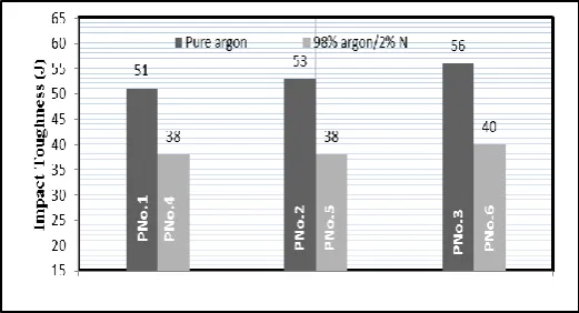
Impact results were affected by heat input. Fig.16 illustrates the impact toughness for PNo.1 to PNo.6 as shown in the Fig. the impact toughness decreased with decreasing the heat input. Lowering in impact toughness is attributed to increasing the delta ferrite content [31].
Impact results were affected also by presence of nitrogen, the comparison shows that impact toughness decreased by about 16J due to presence of nitrogen. Lowering in impact toughness this attributed to formation of nitride that reduces toughness [27]. Also this may be presence of nitrogen in interstitial sold solution as the carbon reduces the toughness.
Fig.16 Comparison between impact toughness of PNo.3 versus PNo.4
3. CONCLUSIONS
The conclusions can be summarized in the following points:-
For the six procedures; change in heat input has an effect on dendritic size, ferrite number and mechanical properties.
[image:6.595.32.297.558.698.2]© 2017, IRJET | Impact Factor value: 6.171 | ISO 9001:2008 Certified Journal | Page 376 attributed to decreasing the cooling rate which leads
to more coarse dendritic structure.
At lowest heat input as in PN.o1, the FN increased, this could be attributed to the increase in cooling rate resulted in large amount of delta ferrite which makes the weldment not suitable for high temperature applications due to sigma phase formation and not suitable for cryogenic applications due to the high ductile to brittle transition temperature.
Using 2% nitrogen in shielding gas increases the tensile strength and reduces FN and the impact toughness.
Presence of nitrogen resulted increasing in hardness and decreasing in impact toughness.REFERENCES
[1] John C. Lippold and Damian J. Kotecki "Welding
Metallurgy and Weldability of Stainless steels", A john Wiley and Sons Publication, 2005, pp. 1, 230, 264, 309.
[2] K. H. Tseng and C. P. Chou "Effect of Nitrogen Addition to
Shielding Gas on Residual Stress of Stainless Steel Weldments "Science and Technology of Welding and Joining", Vol. 7, No. 1, 2001, pp. 57-62.
[3] Subodh Kumar and A.S. Shahi "Effect of Heat Input on
the Microstructure and Mechanical Properties of Gas Tungsten Arc Welded AISI 304 Stainless Steel Joints", Materials and Design, Vol 32, 2011, pp. 3617-3623.
[4] Rati Saluja and K. M. Moeed "The Emphasis of Phase
Transformations and Alloying Constituents on Hot Cracking Susceptibility of Type 304L and 316L Stainless Steel Welds", International Journal of Engineering Science and Technology, May 2012 Vol. 4 No.05, pp. 2206-2216.
[5] Her-Yueh Huang "Effects of Shielding Gas Composition
and Activating Flux on GTAW Weldments", Materials and Design, Vol. 30, 2009, pp. 2404-2409.
[6] Miller "Guidelines for Gas tungsten Arc Welding (GTAW)
", 2013, 215 994 pp. 5.
[7] Y. C. Lin and P.Y. Chen "Effect of Nitrogen Content and
Retained Ferrite on the Residual Stress in Austenitic Stainless Steel Weldments", Material Science and Engineering A307 (2001), pp. 165-171.
[8] Che Wei Kuo, Chi Ming Lin, Gen Huey Lai, Yu Che Chen,
Yung Tse Chang and Weite Wu "Characterization and Mechanism of 304 Stainless Steel Vibration Welding", Materials Transactions, Vol 48, No. 9, 2007, pp. 2319-2323.
[9] Se- Hwan Chi, yong Kwan Shin, Gen Chan Kim, Young Jig
Kim and Jun Hwa Hong "Influence of Ion Irradiation on Hardness Change in Type 304 Stainless Steel Weldment Containing Delta Ferrite", Material Transaction volume 43, No 4, 2002, pp. 627-633.
[10] L. LI and R. W. Messler, JR "The Effects of Phosphorus
and Sulfur on Susceptibility to Weld Hot Cracking in Austenitic Stainless Steels", Supplement to Welding Journal, December 1999, pp. 387-396.
[11] V. P. Kuganpaa, S. A. David and C. L. White "Formation of
Hot Cracks in Austenitic Stainless Steel Welds Solidification Cracking", Welding Research Supplement, August 1986, pp. 203-212.
[12] J. A. Brook, A. W. Thompson "A Fundamental Study of
the Beneficial Effects of Delta Ferrite in Reducing Weld Cracking", Welding Research Supplement, March 1984, pp. 71-83.
[13] Almaida Gigovic Gekic, Mirsada Oruc and Sulejman
Muhamedagic "Effect of Delta Ferrite Content on the Tensile Properties in the Nitronic 60 Steel at and Room Temperature and 750 oC", Materials in Technology / Materials and Technology Vol 46 , May 2012, pp. 519-523.
[14] ASME Section II, Part A, SA 240, "Specification for
Chromium and Chromium-Nickel Stainless Steel Plate, Sheet, and Strip for Pressure Vessels and for General Applications", Edition (2010), pp. 365, 369..
[15] ASME Section II, Part C, SFA 5.9, "ASME Specification for
Bare Stainless Steel Welding Electrodes and Rods", Edition (2010), pp. 204, 225.
[16] ASTM International Designation E407-99 "Standard
Practices for Microetching Metal and Alloys", 1999, pp.4.
[17] AWS A4.2, "Standard Procedures For Calibrating
Magnetic Instruments to Measure the Delta-Ferrite Content of Austenitic and Duplex Austenitic- Ferritic Stainless Steel Weld Metal", 1991, pp. 1-18.
[18] ASME Section (IX), "Boiler and Pressure Vessel Code –
Qualification Standard of Welding and Brazing Procedures, Welders, Brazers, and Welding and Brazing Operators", Edition 2010, pp. 157.
[19] ASME Section II, Part A, SA 370, "Test Methods and
Definitions for Mechanical Testing of Steel Products", 2010, pp. 639.
[20] Chih Chun Hsieh, Dong Yih Lin, Ming-Che Chen, and
© 2017, IRJET | Impact Factor value: 6.171 | ISO 9001:2008 Certified Journal | Page 377
[21] T. Iamboliev, S. Katayama, and A. Matsuanawa
"Interpretation of Phase Formation in Austenitic Stainless Steel Welds", Supplement to welding Journal, December 2003, pp. 337-347.
[22] S. Lun Sin, D. Dube, R. Tremblay "An Investigation on
Microstructural and Mechanical Properties of Sold Mould Investment Casting of AZ91D Magnesium Alloy", Materials Characterization, 59, 2008, pp. 178-187.
[23] ASTM E112-12 "Standard Test Methods for
Determining Average Grain Size"2013, pp. 9-12
[24] T. Kannan and N. Murugan "Prediction of Ferrite
Number of Duplex Stainless Steel Clad Metals Using RSM", Welding Research, Supplement of Welding Journal, May 2006, pp. 91-100.
[25] R. K. Okagawa, R.D.Dixon, and D.L .Olson "The Influence
of Nitrogen from Welding on Stainless Steel Weld Metal Microstructures", Welding Research Supplement, August 1983, pp. 204-209.
[26] W. A. Baeslack, W. F. Savage and D. J. Duquette "Effect of
Nitrogen on the Microstructure and Stress Corrosion Cracking of Stainless Steel Weld Metals", Welding Research Supplement, March 1979, pp. 83-90.
[27] Usama Mohamed "Effect of Welding Parameters on the
Properties of Austenitic Stainless Steel Weldment", M.SC Thesis, Mech. Design and Prod. Eng (Zagazig University), 2009, pp. 5, 13, 27, 82, 100.
[28] C. D. Lundin, W. Ruprecht andG. Zhou "Ferrite
Measurement in Austenitic and Duplex Stainless Steel Castings", Department of Materials Science and Engineering, The University of Tennessee, Knoxville, 1999, pp.20.
[29] C. J. Long and W. T. Delong "The Ferrite Content of
Austenitic Stainless Steel Weld Metal", Supplement to The Welding Journal Sponsored by the American Welding Society and the Welding Research Council (AWS and WRC),, July 1973, pp. 281-297.
[30] S. Nansaarng and C. Chaisang "Influence of Parameters
of Gas Metal Arc Welding on Macrostructures and Mechanical Properties of Austenitic Stainless Steels", 6th WSEAS International Conference on System Science and Simulation in Engineering, Venice, Italy, 2007, Nov 21-23, pp. 144-152.
[31] Norbert friedrich and Gerhard Posch "Welding of
Austenitic Stainless Steel for Cryogenic LNG Applications", Application Technology, Bohler Welding Austria Gmbh, pp. 1-12.
BIOGRAPHY
Dr. Eisa Salem, PhD, Eng.