DESIGN OF SECOND ORDER SIGMA-DELTA MODULATOR
FOR AUDIO APPLICATIONS
1DHANABAL R, 2BHARATHI V, 3NAAMATHEERTHAM R SAMHITHA, 4G.SRI
CHANDRAKIRAN, 5SAI PRAMOD KOLLI
1
Assistant Professor (Senior Grade), VLSI division, SENSE, VIT University,
2
Assistant Professor, GGR College of Engineering, Anna University, Vellore,
3
MTECH Student, SENSE, ECE Department, VLSI Division, VIT University, Vellore,
4
BTECH Student, SENSE, ECE Department, VIT University, Vellore,
5
BTECH Students, SCSE, CSE Department, VIT University, Vellore- 632014, TN, INDIA
E-mail: [email protected],[email protected], 3 [email protected],
4
[email protected], [email protected]
ABSTRACT
The paper includes the design of second order sigma-delta modulator. A comparative study between a first order and second order sigma-delta modulator is carried out. The second order is preferred over the first order sigma-delta modulator due to its better signal-to-noise ratio (SNR). The comparative study between the modulators is done in Matlab, the second-order sigma-delta modulator is designed and modelled in Verilog-A and simulated in Cadence SpectreS. The second order sigma-delta modulator provides an enhancement of 27% in SNR as compared to the first order sigma-delta modulator.
Keywords:Sigma Delta Modulator, SNR, Oversampling, Noise Shaping
1. INTRODUCTION
The precision of signals between the analog and digital interface limits the performance of communication systems as well as Digital Signal Processing. Digital modulation is used to transfer digital bit streams corresponding to the analog signal input. Sigma-delta Modulation (SDM) is a digital modulation technique which can be used as an analog-to-digital converter. In other words, SDM can act as interface between analog and digital signals. The analog-to-digital and digital-to-analog converters form the basic elements of mixed signal IC design.
Generally, the converters operate at Nyquist frequency. But operating in Nyquist frequency limits the speed as well as makes the design of anti aliasing filter complex and critical. On the other hand, SDM uses the techniques of oversampling, noise shaping and filtering that reduce the noise and makes the design simple. SDM converts analog signal into pulse frequency where the number of pulses in an interval can be counted [1] [2]. It is the one of the techniques for converting analog signals into digital. By this, an accurate digital representation of the analog signal can be obtained
during that particular interval. This is one of the reasons why SDM is preferred. In sigma delta modulators, a combination of oversampling & noise shaping (quantization error shaping) are employed. These modulators are designed by simple analog circuits such as a comparator, one or more integrators, and summing circuits [1].
This paper includes an analytical study between a first order and second order sigma-delta modulator. The analysis shows that the second order sigma-delta modulator provides a better SNR value. The second order sigma-delta modulator is then
designed for a given input modulating signal,
f
m
Fig. 1. Noise Shaping
The entire paper is divided into six sections. In section I introduction to SDM is given. In section II properties of SDM are discussed. Section III and IV provides the analysis and modelling of SDM. V and VI section explains about results and conclusions that are obtained respectively.
2. SIGMA DELTA MODULATION
Sigma-delta modulation (SDM) is a technique used for encoding analog signals into digital signals or low-resolution digital signals into high-resolution digital signals. The SDM operation is based on two main signal processing techniques called oversampling & noise shaping [1] [2]. Oversampling includes the sampling of the input modulating
signal,
f
m at a rate greater than the Nyquist rate. Noise shaping is simply quantization error filtering. When we sample and quantize an analog signal, it gives rise to some quantization noise. Quantization noise is due to the rounding-off of the values during quantization.A. Oversampling
A perfect sampling (i.e. sampling at Nyquist rate)
has an RMS quantization noise of
12
∆
which is uniformly distributed within the Nyquist
band
2
sf
(where
∆
LSB is value and fs issampling rate) [2]. If practically the noise is greater than the RMS quantization noise value then the resolution will be less than the required number of bits. In order to avoid this situation, a
higher sampling frequency
Kf
s is being chosen.TheRMS quantization noise of
12
∆
will be present but it is being distributed over a wider
bandwidth,
Kf
s which is greater than theNyquist band. As a consequence of this, the resolution increases. In order to distribute the noise occurred due to quantization over a wide band and to provide an increase in the resolution of bits, oversampling is being employed with an oversampling ratio (OSR),
K
is given by equation (1).Fig. 2. First Order Sigma-Delta Modulator
m s
f
f
K
OSR
2
=
=
(1)
Hence, it can be concluded that oversampling provides an enhancement in the resolution and due to the reduction in the quantization noise, there is an improvement in SNR [2, 3]. The improvement in SNR can be calculated by using equation (2).
76
.
1
log
10
02
.
6
+
+
=
N
OSR
SNR
(2)
B.Noise Shaping
[image:2.595.304.513.356.488.2]SNR given by equation (3). Further, it can be
seen that the circuit also provides an improvement in the resolution.
4
.
3
log
30
02
.
6
+
−
=
N
OSR
SNR
(3) II.Analysis Of First And Second Order Sigma-Delta Modulators
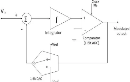
A.First order sigma-delta modulator
The modulator in Fig. 2 illustrates a first order sigma-delta modulator. It comprises of an integrator, a 1-bit quantizer, and a 1-bit DAC. The integrator ramps the input signals up and down. The integrator acts as the noise shaping circuit which shifts the noise from pass band to stop band. The output of the integrator is given to the comparator and then the comparator output is fed back through a 1-bit DAC to the summing circuit.
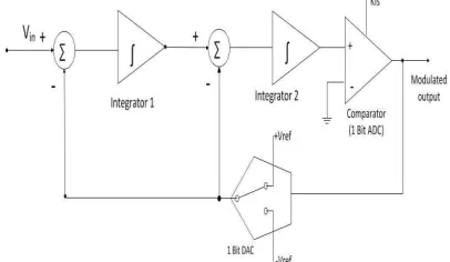
B. Second order sigma-delta modulator
[image:3.595.85.288.607.725.2]Second order sigma-delta modulator as shown in Fig. 3 includes the same components as first order but will include an additional summer and an integrator. The usage of more than one summer and integrator stage in the sigma-delta modulator enables to achieve higher orders of quantization noise shaping. As order is increased, the noise shaping will be better which results in high SNR, but due to the instability by increasing the order, high orders of modulator is not preferred. While using the second order noise shaping circuit we will achieve better resolution for a given over sampling ratio than the first order sigma delta modulator. The analytical study between the first and second order sigma-delta modulators have been carried out. The sigma-delta modulators are setup in Matlab sigma-delta toolbox and then the power spectral density (PSD) and the SNR are obtained for the modulators.
Fig. 3. Second Order Sigma-Delta Modulator
3. MODELLING OF SECOND ORDER
SIGMA-DELTA MODULATOR
The second order sigma-delta modulator is designed in Verilog-A [6] and the output is being simulated in Spectre-S simulator. Using Verilog-A, the compact model of second order and first order sigma-delta model are created. The compact models are used to describe and analyze the performance of the devices. Verilog-A is a high level language which is used to describe the analog behavior of electrical, mechanical systems. The modulated output is then demodulated using Low Pass Filter (LPF) as LPF is the only component used for demodulating sigma modulated output [5]. The output is analyzed and found that the original signal can be reconstructed from the modulated output.
4. RESULTS AND DISCUSSION
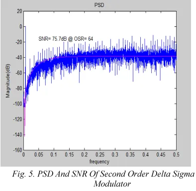
The normal quantizer, delta modulator and first order sigma-delta modulator is analyzed in Matlab and Matlab Simulink [4] [7]. By analyzing the Power Spectral Density (PSD), the noise harmonics of the sigma-delta modulator is found to be very less compared to normal quantizer and delta modulator. Then using the sigma-delta toolbox in Matlab, the SNR and PSD of the first order and second order sigma-delta modulator are analyzed. The Matlab simulation results of SNR and PSD of first and second order sigma-delta modulator are shown in Fig. 4 and Fig. 5, respectively. It is found that the SNR of first order is 55.1dB and that of second order is 75.7dB for an oversampling ratio,OSR=64. Hence, it
[image:4.595.87.514.81.528.2]
Fig. 4. PSD And SNR Of First Order Delta Sigma Modulator
Fig. 5. PSD And SNR Of Second Order Delta Sigma Modulator
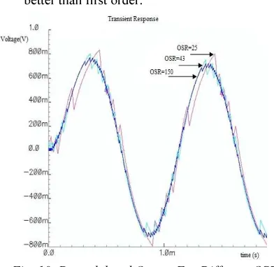
Fig. 10 shows the demodulated output with various values of OSR. It must be noted that the demodulation become effective as the OSR value is being increased. The amount of noise power in the demodulated output is being reduced. The compact model of first and second order sigma delta is simulated in Spectre-S simulator in Cadence. The simulation results which includes the input, clock, modulated output and demodulated output of the first order
[image:4.595.305.511.92.463.2]and second order sigma delta modulator are shown respectively in Fig. 6 and Fig. 7.
Fig. 6. Simulation Results Of First Order Sigma Delta Modulator
[image:4.595.90.333.102.411.2] [image:4.595.87.284.436.628.2]
Fig. 9. PSD Of The Second Order Sigma Delta Modulator
[image:5.595.88.284.409.600.2]The PSD of both the modulators shown in Fig. 8 and Fig. 9 are analyzed and compared. It is been observed that there are more harmonics in the first order than second order, i.e. when second order is used, the over-all noise reduction is better than first order.
Fig. 10. Demodulated Output For Different OSR Values
5. CONCLUSION
As the order of the sigma delta increases the SNR also increases. But due to the limitation on stability higher orders are not preferred. In this paper the first and second order of sigma delta modulator are designed in Verilog-A and simulated in Cadence Spectre-S. While analyzing the PSD, the effect of noise is found to have less effect on second order compared to first order sigma delta modulator. Thus second order sigma delta modulator is efficient.
REFRENCES:
[1] Jose M. de la Rosa., “Sigma-Delta Modulators: Tutorial Overview, Design Guide, and State-of-the-Art Survey”, IEEE Transactions on circuits and systems—I: regular papers, vol. 58, No. 1, Jan. 2011. [2] Sangil Park., “Principles of Sigma-Delta
Modulation for Analog-to-Digital Converters”, APR8/D Rev 1. Motorola. [3] Joshua D. Reiss., “Understanding Sigma–
Delta Modulation: The Solved and Unsolved Issues”. J. Audio Eng. Soc., Vol. 56, No. 1/2, January/February 2008. [4] Thuneibat, S. A., & Ababneh, M. S.,
“Sigma- Delta Modulator Simulation and Analysis using MatLab”. Computer and Information Science, Vol. 5, No. 5. 2012. [5] “Simon Haykin., “Communication
Systems’, Newyork: Jon Wiley & sons,INC.
[6] “Verilog A reference Manual”, Agilent Technologies, 2005.
[7] Jaykar. S, Palsodkar. P, Dakhole, P., "Modeling of Sigma-Delta Modulator
Non-Idealities in
MATLAB/SIMULINK," International
conference on Communication Systems
and Network Technologies (CSNT),