ANTENNA DESIGN FOR WIMAX APPLICATIONS USING
ARTIFICIAL BEE COLONY ALGORITHM
1KANTIDA PREETHI RATNA CHRISTY PRIMSON, 2DR. R.ANITA
1Research Scholar, Anna University
2Professor & Head, Department of Electrical and Electronics
Institute of Road and Transport Technology (IRTT), Erode.
E-mail: [email protected]
ABSTRACT
In wireless communication system, antenna plays as an important component for radiating and receiving the radio waves, where at transmission end and receiving end, respectively. Particularly, the microstrip antennas, which are in the form of integrated circuit, are decisive one to possess the major characteristics of antenna. In this work, a novel design for microstrip antenna is proposed. The design is determined by optimal selection of dimensions, which represent the length and width, of the antenna structure. To optimize the dimensions, Artificial Bee Colony algorithm is proposed in our work. The designed antenna is suitable for the WLAN and WiMAX applications. The experimental results demonstrated that the designed antenna gives ideal radiation characteristics over the operating bands. Subsequently, the performance is compared in detail with the existing designs.
Keywords: Microstrip Antenna, Parameter Optimization, Neural Network, Artificial Bee Colony Algorithm, Wimax.
1. INTRODUCTION
In recent years, development of science and technology in wireless communications has obtained significant attention, particularly in high demand to increase performance rates [1]. The growth of the dual band mobile sets and smart phones are rapidly increasing in developing countries [2]. This is because of that wireless communications have been developed widely and promptly in the modern world. This leads to a great response in designing compact, multiband and low-cost antennas for portable wireless terminal devices [3]. Especially, multi-band operation becomes challenging in practical applications for broadband access in the wireless metropolitan area network
(WMAN) environment [4]. Nowadays, wireless
local area network (WLAN) and Worldwide Interoperability for Microwave Access (WiMAX) have been extensively applied in mobile devices. These two are cost-effective, viable, high-speed data connectivity solution, and enabling user mobility [5].
Despite the increasing demand for high-speed internet access in areas where wireless local area
networks (WLAN) cannot reach, WiMAX
technology has been established as an alternative to provide long-range wireless broadband services [6]. The wireless communication standard WiMax has been accepted by the IEEE 802.16 working group. It has the coverage area up to 50km radius
[7].For mobile internet access, this device provides
wireless transmission of data from single point-to-multi point links. This technology is also called as broadband wireless access [8]. Basically, WiMAX has three allocated frequency bands called as low band, middle band and high band. These frequency ranges are 2.5 GHz to 2.8 GHz, 3.2 GHz to 3.8 GHz, and 5.2GHz to 5.8GHz [9]. It is in practice to integrate systems of different frequency bands into a single product to provide multiple functions [10].
However in order to cover the WiMAX bands, a
bandwidth, beam width resonant frequency, polarization, pattern, and impedance [13].The basic idea of microstrip antenna came from utilizing printed circuit technology not only for the circuit component and transmission lines but also for the
radiating elements of an electronic system [14]. It
has several advantages over other antennas such as a low profile, light-weighted, cost effective, easy fabrication process [15].
Besides, fractal monopole antennas with their iterative structure show good performance for multiband applications, but they achieve less
flexibility [16].Many researchers designed various
shapes of antenna for wideband [17]. In the recent literature, several multiband antennas have been presented, including the monopole antenna with double S-shaped radiation patches, the slot-ring coupled patch antenna, the CPW-fed planar monopole antenna, and two notched bands in the wideband antenna. Even though these antennas exhibit good multiband performance, they are slightly complicated in structure [18]. The desired antenna design has to cover both the WiMAX and WLAN systems [19]. So we require an advanced antenna design, which should take effort not only on bandwidth & operating frequency but also on antenna bandwidth, where as the impedance is also reduced [20].
The rest of the paper is organized as follows. Section II describes the literary works related to different types of antenna design for multiband applications followed by section III, which designates the microstrip antenna modeling and parameter optimization through artificial bee colony algorithm. The performance of the proposed technique to achieve the radiation characteristics and their comparison of the simulated results with existing systems are discussed in section IV. Finally the future enhancements and concluding remarks are given in section V.
2. LITERATURE SURVEY
Despite a plenty of research works are available in the literature, a handful of relevant research works have been briefly reviewed here.
Wen-Chung Liu et al. [21] have proposed the
design of a novel monopole antenna for triple frequency operation. In this system, the protrudent strips and cross shaped strip line was used for the purpose of loading and feeding the radiating elements. Particularly, the ground was cut out by shaped slots in the proposed system. By means of assigning these elements, the antenna can stimulate
the triple resonances with good radiation performance to cover the wireless communication systems. By exactly selecting the dimensions of the antenna, the virtuous triple-broad impedance bandwidths and radiation characteristics was
accomplished for the multiband wireless
communication systems. Using these dimensions dependent antenna design, the large surface wave loss was avoided, the impact on the coupling effect was decreased and also the overall size of the antenna was reduced.
Hsien-Wen Liu et al. [22] have proposed the
antenna, which is just composed of a pentagonal radiating patch with two thin bent slots etched on it. Based on proper selection of the positions and lengths of these slots, the undesired frequencies can be restricted in the stop band without mishap in the radiation performance. In this antenna, the band prohibited property is also tunable. Thus this design has good omni-directional radiation patterns through significant gain across the operating bands. It has a simple structure and easy to construct to be fixed inside the portable devices. Therefore, this antenna was very crucial one for the multiband applications.
X. L. Sun et al. [23] have contributed the design
of dual band monopole antenna with tunable frequency. In this design, the radiator contains a short stem connecting with two branches to produce the two frequency bands closer to 2.4 and 3.4 GHz. By properly placing a varactor among the relevant branch and the short stem of the radiator, the tunability of the frequency band was attained. Here, to avoid severe effects on the antenna performance the novel biasing circuit was designed for the varactor.
Jui-Han Lu et al. [24] have revealed the design
of planar antenna with multiband communication. It has very compact C-shaped and inverted L-shaped slots to obtain the Omni directional radiation patterns with good antenna gain and radiation efficiencies. This model has worked on to deliver the inclusive impedance bandwidth corresponds to the bands. To achieve good impedance matching, the length and width of the T-shaped microstrip line was properly adjusted in this system. This proposed antenna has compact in operation, simply invented at low cost, and suitable for printed on the system circuit board for the convenient devices.
Gary C.-Y. Chen et al. [25] have proposed the
broadband yagi antenna for various wireless
an active element and inverted-L structure as parasitic elements are used in the array configuration. This scheme fulfills the good front to back ratio for the radiation. In order to achieve different gain profiles, the multiple directors were used in this system. By using a single yagi antenna with one reflector and director, the Omni directional radiation pattern and the gain around 3dB was accomplished. In accordance with this design, the optimum broadband characteristics were achieved by the measured return loss.
3. PROPOSED METHODOLOGY
In antenna design, modeling of the structure is an imperative aspect. Recently, the multi band antennas have been designed to attain the worldwide interoperability for microwave access (WiMAX) applications. Especially, microstrip antennas are recently constructed for it. There are many kinds of materials used to optimize the structural modeling of an antenna. Through these methods, we can improve the properties of an antenna in terms of return loss, antenna efficiency, and antenna gain measures. In this paper, we
introduce a new mathematical modeling
optimization technique related to the consideration of the parameters used in the antenna. Here, the antenna parameters are dealt with the dimensions of the patches. And also we select the microstrip monopole antenna modeling to apply this optimization process and improve the performance. The proposed optimization method is discussed below in detail.
3.1 Parameter Optimization
All the parameters in a microstrip antenna design control the properties of this antenna. In the part of antenna design, we may concentrate on many constraints. In order to build the ideal antenna structure, the dimension constraint takes place in our proposed system. The dimension is nothing but an essential parameter for the antenna modeling. It comprises the length and width of the protrudent strips and cross shaped strip line in the configuration of an antenna. The length of the patch, termed as L, controls the resonant frequency. The width, termed as W, controls the input impedance and the radiation pattern. The larger width can increase the bandwidth. The dataset for the dimension based optimization used in our design has to be more suitable to enhance
the antenna performance for wide band
applications. Based on the proper selection of dimensions in an antenna, we can minimize the
antenna size also. In particular, the enhancement of return loss can also be achieved by our parameters for different frequencies. The structural modeling of our proposed system explains below in detail.
Microstrip Antenna Structure Modeling: The proposed microstrip antenna is a formation of cross shaped strip line and defected ground structure. In this design, the radiator and ground plane are fixed on the opposite sides of a printed-circuit board with a dielectric constant of 4.4 and substrate thickness of 1.6 mm. A cross shaped strip line includes both the vertical and horizontal strips. The ground plane has the overall size with dimensions L × W. The calculation of the length and width of the antenna is the important aspect in the mathematical modeling of the proposed system.
Calculation of the Width (W):
1 2 2 1 0 0 + = r r f W ε ε µ (1) 1 2 2 + = r r f C W ε (2)
Where,
C
= Free space velocity of lightr
ε
= Dielectric constant ofsubstrater
f
= resonant frequency0
µ
=Permeability of free space0
ε
=Permittivity of free spaceThe effective dielectric constant of the microstrip antenna is used for fringing field. The effective dielectric constant is calculated from,
+ − + + = w h r r eff 12 1 1 2 1 2 1 ε ε ε (3)
The actual length of the patch (L): L
L
L= eff −2∆ (4)
Where, eff r eff
f
c
L
ε
2
=
(5)
∆
L
= Line extensionThe performance analysis of the antenna characteristics are described below.
3.2 Desired characteristics analysis of antenna
The radiation characteristics exhibit the
performance of proposed antenna in terms of return loss, bandwidth, directivity, efficiency, and antenna gain.
3.2.1 Return Loss
This is the finest and suitable method to calculate the input and output signal sources. It can be said that the loss of signal power causing from the reflection is produced at a discontinuity in a transmission line. This loss that is returned is called as Return Loss. It is determined in decibels (dB) as follows.
r i P p dB
RL( )=10log10
(6)
Where,
i
p
= incident powerr
P
= reflected powerIt is the measure of how well devices are matched. It also has the better determination for small values of reflected wave. The minimization of the antenna return loss is an important feature in our proposed work.
3.2.2 Bandwidth
It is one of the antenna parameters. It defines the range of frequencies over which the antenna can suitably radiate or receive energy. The preferred bandwidth is one of the defining parameters used to decide upon an antenna.
3.2.3 Antenna Gain
It is usually defined as the product of the antenna efficiency and the directivity of the antenna. By means of reciprocity, the gain of any antenna in the transmitting side is identical to its gain in the receiving end. It is typically expressed in terms of dB.
D G
R ε
= (7)
Here,
G
= Antenna GainR
ε
= Antenna Efficiency
D
= DirectivityDirectivity (D) is the important parameter of the
antenna. It expresses the direction of the antenna’s radiation pattern. If the antenna radiates equally in all the directions, the directivity will be on zero. It is technically a function of angle.
Antenna Efficiency
It is defined as the proportion of the radiated power to the input power of the antenna. It is also named as radiation efficiency.
input radiated R
P P =
ε (8)
Where,
P
input= input power in watts
P
radiated = (Gain – Loss). It indicates the radiated power of the antenna.For the parameter optimization, we have the required dimensions for our proposed antenna structure design. To optimize the dimensions, we introduce the new optimization algorithm called as Artificial Bee Colony algorithm followed by determining the performance measures. PCADD software is used to develop the initial dataset of parameters in the microstrip antenna.
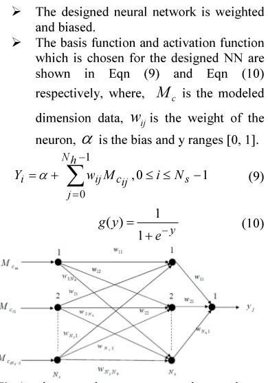
3.3 Dataset Training using Feed Forward Neural Network
Neural networks are also known as artificial neutral network. For modeling and design of antenna recently neural network computational modules have got acceptance as an unorthodox and useful tool. neural networks (NN) have been used to the structure and the functionality of biological nature of human brain. Therefore, ANN is found to be more flexible and apposite than other modeling methods [26].
The ANN consists of three layers: input, output and hidden layer. They are composed of a series of computational node structured into several layers. Each node is connected to all the nodes in the previous layer.
The modeled dataset of antenna is applied for training the feed forward neural network with back propagation. The neural network to train the
dimension dataset is shown in the fig (1).
The steps to be followed in this process are given below.
Set the input weights of every neuron in
the network with
N
s''input layers, a ''g
N
The designed neural network is weighted and biased.
The basis function and activation function
which is chosen for the designed NN are shown in Eqn (9) and Eqn (10)
respectively, where,
M
c is the modeleddimension data,
w
ijis the weight of theneuron,
α
is the bias and y ranges [0, 1].∑
−=
− ≤ ≤ +
=
1
0
1 0
,
h N
j
s ij
c ij
i w M i N
Y α (9)
y
e y g
−
+ =
1 1 )
[image:5.595.101.512.66.775.2]( (10)
Fig 1: n inputs and one output neural network to train the dataset
The basis function, which is given in eqn.
(9), is commonly used in all the remaining layers (hidden and output layer). The output of the ANN is determined by
giving
M
cas the input. The actual outputis calculated by multiplying output bias by eqn. (10).
The learning error is determined for the
Neural Network.
∑
− =− =
1
0
2
) ( 1 Ns
b
b s
Y D N
E
(11)
Where,
E
is the error in the NN
D
- Desired output
Y
b - Actual outputFitness = square root of (
E
) (12)After the error calculation in each
iteration, weight optimization has been applied to mitigate the error in the network.
Weight optimization using hybrid of GA
and ABC algorithm is applied in our work. In this optimization technique, the weights are given as the inputs. (i.e.) the genes in a chromosome are the weights. Here the fitness function is the average error of the neural network output. This function is calculated for every weight adjustment in the NN.
When the error gets minimized to a
minimum value, it is taken that the designed ANN with optimum weights is well trained for its further testing phase and the hybrid of GA and ABC
[image:5.595.97.292.124.402.2]The final trained dataset is used for the proposed optimization process.
Fig 2: Neural Network training and testing
Table 1: Dataset For ANN Model
Inputs ANN
outputs
PCADD outputs Patch
length (cm)
Patch Width (cm)
Substrate thickness
(cm)
Dielectric constant
Feed line width
(cm)
Return Loss (dB)
0.6 0.2 0.16 4.4 0.2 -2 -2
2.7 2 0.16 4.4 0.2 -3.5589 -3
7.5 6 0.16 4.4 0.2 -3 -3
7.6 6.1 0.16 4.4 0.2 -3 -3
7.7 6.2 0.16 4.4 0.2 -3 -3
[image:5.595.98.513.407.756.2]8.1 6.6 0.16 4.4 0.2 -2.9973 -3
8.2 6.7 0.16 4.4 0.2 -2.9913 -3
8 6.5 0.16 4.4 0.9 -2.8518 -3
8 6.5 0.16 4.4 1.2 -3 -3
3.4 Artificial Bee Colony Algorithm
It is a robust, simple and population based
stochastic optimization algorithm. This
optimization, which performs based on a particular intelligent behavior of honeybee swarms, is easy to implement. The colony consists of three groups of bees.
• Employed bees
• onlooker bees
• Scout bees
The number of food sources is equal to the number of employed bees and onlooker bees in the hive. This novel optimization algorithm performs to attain the better antenna performance rather than the existing system. In particular, this algorithm is realistic to mitigate the return loss of the antenna by applying different dimensions in our proposed work. In the proposed system, multi objective functions are used. It defines the bandwidth, directivity, efficiency and antenna gain. The radiation efficiency and the directivity correlate with the gain of the antenna. The steps of the artificial bee colony algorithm are given below in detail.
Pseudo Code for the ABC algorithm:
Initialize the population of the food sources. The
initial food sources are selected randomly in this work. The employed bees are allocated depends on the food sources.
REPEAT Employed bees
Employed bees are assigned to go to the food sources and determine the neighborhood food sources in the search space. Then, bees are memorizing those food sources and evaluate their nectar amount. Finally it performs the dance in the hive.
Onlooker bees
Everyonlooker bee is used to watch the dance of
the employed bees. Based on its dance, it can select the better sources and it will go to that sources and chooses the neighborhood sources around that. Now onlooker bees evaluate the nectar amount.
Scout Bees
Bees used to select the abandoned food sources and replace those sources by new food sources are called as Scout bees.
Memorize the best solution achieved so far
UNTIL the requirements are met
Steps to find the optimum dimensions: Consider the optimization problem as follows. Minimize [
f
(
x
)
] = [f
(
D
)
]Here,
D
=
D
1,
D
2,...
D
n
f
(D
)
= Return loss of an antenna
D
n= n number of dimensions in the dataset.In our design, the input parameters are patch length, patch width, substrate thickness, dielectric constant, feed line width, and center frequency. The return loss of the designed antenna is calculated in accordance with the dimensions of the microstrip antenna.
First we initialize the position of all food sources. In ABC algorithm, each food source position represents a set of the dimensions. The initial population is generated randomly in this phase. Here the solution represents the return loss of the antenna.
n
x x x
x= 1, 2,...
(9)
The
f
(
x
)
values are calculated using thetrained antenna dataset. The fitness function is calculated by
< +
≥ +
=
0 )
( 1
0 1
1
i i
i i i
f if f abs
f if f
fit (10)
• Fitness evaluation phase – The employed bees are in search for new food sources having more nectar within the neighborhood of the food source in their memory. After that it evaluates the fitness of the neighborhood food source.
To produce the new solution from the previous solution, the employed bees use the following equation
)
( , ,
, ,
,j i j i j i j k j
i x x x
v = +Φ −
(11)
• Calculate the probability values p for the solutions x by means of their fitness values by using the formula,
∑
= = /2
1
cs
i i i i
fit fit
p (12)
• Onlooker bees produce new solutions from the
selected solutions depending on
p
i and evaluatethem.
• If the new solution has equal or better fitness
than the old solution, then it is changed with the old one in the memory. Otherwise, the old is retained. If a solution is not improved over a predetermined number of cycles, then that food source is assumed to be abandoned. The abandoned food source is replaced by new food source generated by scout bees.
• This procedure is continued until the
termination criterion is reached.
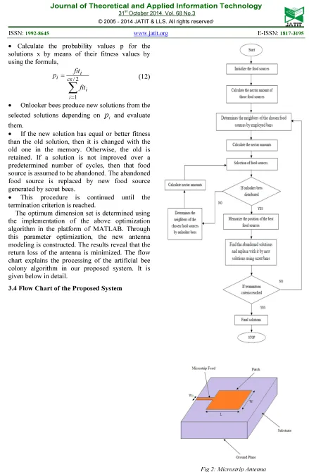
The optimum dimension set is determined using the implementation of the above optimization algorithm in the platform of MATLAB. Through this parameter optimization, the new antenna modeling is constructed. The results reveal that the return loss of the antenna is minimized. The flow chart explains the processing of the artificial bee colony algorithm in our proposed system. It is given below in detail.
[image:7.595.76.515.68.738.2]3.4 Flow Chart of the Proposed System
4.EXPERIMENTAL RESULTS AND DISCUSSION
[image:8.595.298.516.72.288.2]Simulation of the proposed antenna system is discussed in this section. It is implemented in the MATLAB simulation tool. This simulation results express the performance analysis of the proposed system and compared with existing techniques. The performance of the proposed design includes some main constraints. They are return loss, bandwidth, directivity, efficiency and antenna gain. In simulation part, the initial solutions were developed from the PCADD software. Then those solutions are given to the neural network to train the dataset. After training process, the new optimized final dataset values are obtained and subjected to optimization via MATLAB to attain the final simulated results. By varying the input parameters like patch length, patch width, feed line width, the minimized return loss was achieved and the corresponding bandwidth, directivity, antenna efficiency were also determined in our proposed system. Finally, the return loss against center frequency for this proposed antenna was plotted by the final values. The figure.2) describes the proposed rectangular line-fed microstrip antenna with dielectric constant of 4.4 and substrate thickness 0.16.
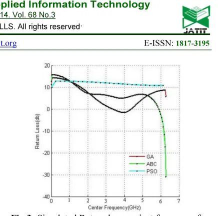
Fig 3: Simulated Return loss against frequency for the proposed antenna
Fig.3) describes the return loss of the proposed microstrip antenna against the center frequency
[image:8.595.102.491.553.636.2]with the optimum input parameters and also compares the performance with conventional methods. These are listed below in table.2). This table represents the final value of the return loss for proposed system and compared with other algorithms like genetic algorithm (GA) and particle swarm optimization algorithm (PSO). It reveals that the proposed system have the minimized return loss values. Table.3) describes the results of directivity, antenna efficiency, bandwidth and antenna gain for the final proposed design of the rectangular line-fed microstrip antenna. Fig .4 depicts the performance of the proposed microstrip antenna in terms of antenna gain over varying operating bands. It shows the better improvement than the existing systems.
Table 2: Simulation Results Of Return Loss
Inputs Output
Patch length(cm)
Patch width(cm)
Feed line width
(cm)
Substrate thickness(cm)
Dielectric constant
Return loss (dB)
ABC 11.3 1.8 1.2 0.16 4.4 -5.71723
GA 3.5 0.8 0.6 0.16 4.4 1.735574
Table 3: Simulation Results Of Efficiency, Directivity And Antenna Gain
Input Outputs for L=11.3, W=1.8, Wf =1.2
Frequency (GHz)
Efficiency (%) Directivity (dB) Antenna Gain
(dBi)
Bandwidth (%)
0.627 21.9 5.9 1.11 0.3
1.1 40.6 8.1 5.17 2.4
2 52.6 7.7 6.07 1.1
3 62.9 6.7 6.24 43.7
4 68.7 8.2 7.50 3.4
5 70.9 9.1 8.09 12.6
6 73.7 9.6 8.49 10.3
7 74.9 10.1 8.78 7.6
The antenna gain is calculated by multiplying antenna efficiency and directivity of the microstrip antenna. In proposed system, the return loss is decreased across different operating bands. The minimization of return loss was done by proper dimension optimization in microstrip antenna design.
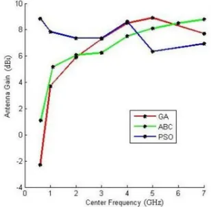
Fig 4: Simulated Antenna Gain Across Operating Bands
In Fig.4), conventional methods like GA, PSO are compared with the proposed ABC algorithm to demonstrate the antenna gain across different frequencies. PSO exhibits better antenna gain at initial frequency bands, but at higher bands, some fluctuations occurred in gain because of decreased antenna efficiency. GA has high antenna gain values in the range of 2 to 5 GHz frequencies. Nevertheless, negative deviations occurred in higher operating bands. Here we can get the small size antenna however it has high return loss. The proposed artificial bee colony algorithm discloses good antenna gain for all resonant frequencies. It has no fluctuations over the entire frequency bands. Therefore the antenna gain is rapidly increased by
choosing the proper parameters for microstrip antenna.
Through the simulated results, the proposed microstrip antenna exhibits good return loss and antenna gain for different frequency bands. Hence the proposed antenna can stimulate triple resonances and has an appropriate radiation performance to accommodate the operation requirements of both 2.4/5.2/5.8 GHz WLAN and the 3.5/5.5 GHz WiMAX communication systems.
5. CONCLUSION
In our work, we proposed a new rectangular microstrip antenna design technique for attaining efficiency in the WiMAX applications. It comprises new optimization approach in part of selecting parameters of the antenna. NN was used for training the dataset of the antenna parameters. The proposed ABC optimization algorithm has been formulated to deal with the performance of the microstrip antenna. The prototype of the proposed antenna with optimum dimensions was developed in the working platform of MATLAB and experimentally studied in this work. The optimum dataset of the dimensions exposes the essential radiation characteristics such as return loss, directivity, and efficiency at every operating frequency of the antenna. By using this proposed design 3.5/5.5 GHz operations were achieved for WiMAX applications. The performance of the proposed design was demonstrated and compared with the conventional methods like GA and PSO.
REFERENCES
[1] Ramli, N., Ali, M.T.,Yusof, A.L., and Ya'acob, N., ”Frequency Reconfigurable Stacked Patch Microstrip Antenna (FRSPMA) for LTE and WiMAX Applications”, In proceedings of
International Conference on Computing,
[image:9.595.110.264.377.528.2](ComManTel), Page(s):55 – 59, Ho Chi Minh City, Vietnam, 21-24 Jan. 2013.
[2]S. Venkatrami Reddy, Aditya Singh, Yadu Nath. K and M. Jaleel Akhtar,”Design of a Practical
Dual-band PlanarMonopole Antenna for
WLAN and WiMAX Applications”, In proceedings of National Conference on
Communications (NCC), Page(s):1 – 5, New
Delhi, India,15-17 Feb. 2013.
[3] Wei Hu, Ying-Zeng Yin, Peng Fei, and Xi Yang, “Compact Triband Square-Slot Antenna
With Symmetrical L-Strips for
WLAN/WiMAX Applications”, IEEE
transactions on Antennas and Wireless
Propagation Letters, Volume:10, Page(s):462 – 465,2011.
[4] Lu, J.-H.,and Huang, B.-J., “Planar multi-band
monopole antenna with L-shaped parasitic strip
for WiMAX application”, Electronics Letters,
Volume: 46, Issue: 10, Page(s):671 – 672, May
13 2010.
[5] Chitra R.J., Karthik B.R., and Nagarajan V., “Design of double L-slot microstrip patch antenna for WiMAX and WLAN application”, In proceedings of International Conference on Computing, Communication and Applications (ICCCA), Page(s):1 – 4, Dindigul, Tamilnadu, 22-24 Feb 2012.
[6] C.Y.D. Sim, H.D. Chen, K.C. Chiu, and C.H.
Chao., “Coplanar waveguide-fed slot antenna
for wireless local area network/worldwide
interoperability for microwave access
applications”, IET Microwaves, Antennas &
Propagation, Vol. 6, Iss. 14, page(s):1529–
1535, 2012.
[7] Boutheina Tlili, “Design of Double C-Slot
Microstrip Patch Antenna for WiMax
Application”, In proceedings of Antennas and Propagation Society International Symposium
(APSURSI),IEEE,Page(s):1 – 4,Toronto, ON,
11-17 July 2010.
[8] V.Ratna Bhargavi, P.Poorna Priya, K.Pavan
Kumar, and Dr.Habibulla Khan, “Gain
enhancement of v-slotted triangular shape
microstrip patch antenna for WiMax
applications”, International Journal of
Engineering Research and Applications
(IJERA), Vol. 2, Issue 3,pp. 1187-1193,
May-Jun 2012.
[9] Gary C.-Y. Chen, K. K.-M. Chan, and K. Rambabu, “Miniaturized Yagi Class of Antennas for GSM, WLAN, and WiMax Applications”, IEEE transactions on Consumer
Electronics, Volume: 56, Issue: 3,Page(s):1235
– 1240,Aug. 2010.
[10] Liu-Tao Ma,Fu-Shun Zhang,andWei-Mei Li,
“A novel multi-band antenna for WLAN and WiMAX applications”, In proceedings of the 10th International Symposium on Antennas,
Propagation & EM Theory (ISAPE),
Page(s):238 – 241,Xian, 2012.
[11] Huiqing Zhai, Zhihui Ma, Yu Han, and
Changhong Liang, “A Compact Printed Antenna for Triple-Band WLAN/WiMAX Applications”, IEEE transactions on Antennas and Wireless Propagation Letters, Volume: 12,
Page(s):65 – 68,09 January 2013.
[12] R.Jothi Chitra, M.Rajasekaran and
V.Nagarajan , “Design of double L-slot
Microstrip Patch Antenna Array for
WiMAX/WLAN Application using step width junction feed”, In proceedings of International Conference on Communications and Signal Processing (ICCSP), Page(s):298 – 304, Melmaruvathur, India, 2013.
[13] Chitra,R.Jothi ; Yoganathan, M. ; and
Nagarajan V., “Co-axial Fed Double L-Slot
Microstrip Patch Antenna Array for WiMAX and WLAN Application”, In proceedings of International Conference on Communications and Signal Processing (ICCSP), Page(s):1159 –
1164,Melmaruvathur, India,3-5 April 2013.
[14] Irfan, N., Yagoub, M.C.E., and Hettak, K.,
“Design and FDTD Analysis of Single-Band and Dual-Band Antennas for RFID and WiMAX Applications”, In proceedings of 19th
International Conference on Software,
Telecommunications and Computer Networks
(SoftCOM), Page(s):1 -5 Split, 15-17
Sept.2011.
[15] R.Jothi Chitra, K.Jeyanthi, and
V.Nagarajan,“Design of E Slot Rectangular
Microstrip Slot Antenna for WiMAX
Application”, In proceedings of International Conference on Communications and Signal
Processing (ICCSP), Page(s):1048 – 1052,
Melmaruvathur, India, 2013.
[16] Raha Eshtiaghi, Mahrokh G. Shayesteh, and
Navid Zad-Shakooian, “Multicircular
Monopole Antenna for Multiband
Applications”, IEEE transactions on Antennas
and Wireless Propagation Letters,Page(s):1205
– 1207,Volume:10,20 October 2011.
International Conference on Control
Automation and Systems (ICCAS),
Page(s):2206 – 2209, Gyeonggi-do, 27-30 Oct.
2010.
[18] Pingan Liu, Yanlin Zou, Baorong Xie,
Xianglong Liu, and Baohua Sun,” Compact
CPW-Fed Tri-Band Printed Antenna with
Meandering Split-Ring Slot for
WLAN/WiMAX Applications”, IEEE
transactions on Antennas and Wireless
Propagation Letters, Volume:11, Page(s):1242
– 1244,18 October 2012.
[19] Chia-Mei Peng, I-Fong Chen, and Ji-Wei Yeh, “Printed Broadband Asymmetric Dual-Loop Antenna for WLAN/WiMAX Applications”,
IEEE transactions on Antennas and Wireless
Propagation Letters, (Volume: 12), Page(s):898
– 901,12 July 2013.
[20] Rashid F., Mustafiz M.M., Ghosh and M.K., Hossain, S, “Design and Performance Analysis of Ultra Wideband Inverted-F Antenna for
Wi-Fi, WiMAX, WLAN and Military
Applications”, In (ICCIT), Page(s):610 – 614,
Chittagong,22-24 Dec 2012.
[21] Wen-Chung Liu, Chao-Ming Wu, and Yang Dai, “Design of Triple-Frequency Microstrip-Fed Monopole Antenna Using Defected
Ground Structure”, IEEE transactions on
antennas and propagation, Vol. 59, Issue: 7,
Page(s): 2457 – 2463,July 2011.
[22] Hsien-Wen Liu, Chia-Hao Ku, and Chang-Fa Yang, “Novel CPW-Fed Planar Monopole Antenna for WiMAX/WLAN Applications”, IEEE transactions on antennas and propagation
Letters, Vol. 9, Page(s):240 – 243, 08 March
2010.
[23] X. L. Sun, S. W. Cheung, and T.I.Yuk,
“Dual-Band Monopole Antenna with Frequency-Tunable Feature for WiMAX Applications”, IEEE transactions on antennas and propagation
Letters, Volume: 12, Page(s):100 – 103, 23
January 2013.
[24] Jui-Han Lu and Bing-Jhang Huang, “Planar Compact Slot Antenna with Multi-Band Operation for IEEE 802.16m Application”,
IEEE Transactions on Antennas and
Propagation, Volume: 61, Issue: 3,
Page(s):1411 – 1414,15 November 2012.
[25] Gary C.-Y. Chen, K. K.-M. Chan, and K. Rambabu, “Miniaturized yagi class of antennas for GSM, WLAN, and WiMax applications”, IEEE Transactions on Consumer Electronics,
Volume: 56, Issue: 3, Page(s):1235 – 1240, 28
October 2010.
[26] Abdalla O.A., Zakaria M.N., Sulaiman S., Ahmad, W.F.W., “A comparison of feed-forward back-propagation and radial basis artificial neural networks: A Monte Carlo
study”, In proceedings of international
symposium in information technology,