An Enhanced IUPQC Controller to Provide Grid Voltage
Regulation
D Ravi Kiran1, K N S K Santhosh2
M.Tech Student, Department of EEE, KIET-II, Kakinada, India.1 Asst. Professor, Department of EEE, KIET-II, Kakinada, India.2
Abstract- This paper shows an enhanced controller for the double topology of the brought unified power quality conditioner (iUPQC) developing its materialness in power-quality remuneration, and additionally in smaller scale network applications. By utilizing this controller, past the traditional UPQC control quality components, including voltage list/swell remuneration, the iUPQC will likewise give responsive power support to manage the load-bus voltage as well as the voltage at the matrix side bus.A FUZZY controller is executed in this venture in the place of PI controller. IUPQC will fill in as a static synchronous compensator (STATCOM) at the network side, while giving likewise the routine UPQC pay at the heap or small scale framework reproduction results are given to check the new usefulness of the hardware. Reenactment results are introduced to confirm the practicality of the proposed approach in MATLAB/SIMULINK condition.
Index Terms— iUPQC, microgrids, powerquality, static synchronous compensator (STATCOM), unified power quality conditioner (UPQC), Fuzzy controller. I INTRODUCTION
Unquestionably control hardware gadgets have achieved awesome innovative upgrades. Be that as it may, the expanding number of force hardware driven burdens utilized by and large in the business has achieved unprecedented power quality issues. Interestingly, control hardware driven loads for the most part require perfect sinusoidal supply voltage keeping in mind the end goal to work legitimately, though they are the most dependable ones for anomalous symphonious streams level in the appropriation framework. In this situation, gadgets that can alleviate these downsides have been produced throughout the years. A portion of the arrangements
include an adaptable compensator, known as the brought together power quality conditioner (UPQC) bound together powerquality conditioner (UPQC) [1]– [7] and the static synchronous compensator (STATCOM) [8]–[13]. The power circuit of an UPQC comprises of a mix of a shunt dynamic channel and an arrangement dynamic channel associated in a consecutive design. This mix permits the synchronous remuneration of the heap current and the supply voltage, so that the repaid current drawn from the framework and the repaid supply voltage conveyed to the heap are kept adjusted and sinusoidal. The double topology of the UPQC, i.e., the iUPQC, was exhibited, where the shunt dynamic channel carries on as an air conditioner voltage source and the arrangement one as an air conditioner current source, both at the essential FREQUENCY. This is a key indicate better outline the control picks up, and also to upgrade the LCL channel of the power converters, which permits enhancing altogether the general execution of the compensator . The STATCOM has been utilized broadly in transmission systems to manage the voltage by method for element responsive power pay. These days, the STATCOM is to a great extent utilized for voltage control , though the UPQC and the iUPQC have been chosen as answer for more particular applications, Moreover, these last ones are utilized just specifically cases, where their moderately high expenses are supported by the power quality change it can give, which would be unfeasible by utilizing customary arrangements. By joining the additional usefulness like a STATCOM in the iUPQC gadget, a more extensive situation of uses can be come to, especially if there should be an occurrence of appropriated era in shrewd networks and as the coupling gadget in lattice tied smaller scale matrices. the execution of the iUPQC and the UPQC was analyzed when functioning as UPQCs. The fundamental distinction between these compensators is the kind of source imitated by the arrangement and shunt control converters. In the
An Enhanced IUPQC Controller to Provide Grid Voltage
Regulation
D Ravi Kiran1, K N S K Santhosh2M.Tech Student, Department of EEE, KIET-II, Kakinada, India.1 Asst. Professor, Department of EEE, KIET-II, Kakinada, India.2
Abstract- This paper shows an enhanced controller for the double topology of the brought unified power quality conditioner (iUPQC) developing its materialness in power-quality remuneration, and additionally in smaller scale network applications. By utilizing this controller, past the traditional UPQC control quality components, including voltage list/swell remuneration, the iUPQC will likewise give responsive power support to manage the load-bus voltage as well as the voltage at the matrix side bus.A FUZZY controller is executed in this venture in the place of PI controller. IUPQC will fill in as a static synchronous compensator (STATCOM) at the network side, while giving likewise the routine UPQC pay at the heap or small scale framework reproduction results are given to check the new usefulness of the hardware. Reenactment results are introduced to confirm the practicality of the proposed approach in MATLAB/SIMULINK condition.
Index Terms— iUPQC, microgrids, powerquality, static synchronous compensator (STATCOM), unified power quality conditioner (UPQC), Fuzzy controller. I INTRODUCTION
Unquestionably control hardware gadgets have achieved awesome innovative upgrades. Be that as it may, the expanding number of force hardware driven burdens utilized by and large in the business has achieved unprecedented power quality issues. Interestingly, control hardware driven loads for the most part require perfect sinusoidal supply voltage keeping in mind the end goal to work legitimately, though they are the most dependable ones for anomalous symphonious streams level in the appropriation framework. In this situation, gadgets that can alleviate these downsides have been produced throughout the years. A portion of the arrangements
UPQC approach, the arrangement converter is controlled as a non sinusoidal voltage source and the shunt one as a no sinusoidal current source. Henceforth, progressively, the UPQC controller needs to decide and incorporate precisely the symphonious voltage and current to be adjusted. Then again, in the iUPQC approach, the arrangement converter acts as a controlled sinusoidal current source and the shunt converter as a controlled sinusoidal voltage source. This implies it is not important to decide the symphonious voltage and current to be adjusted, since the consonant voltages show up actually over the arrangement current source and the symphonious streams stream normally into the shunt voltage source. In real power converters, as the exchanging FREQUENCY expands, the power rate ability is diminished. Consequently, the iUPQC offers better arrangements if contrasted and the UPQC if there should arise an occurrence of high-power applications, since the iUPQC remunerating references are unadulterated sinusoidal waveforms at the essential FREQUENCY. In addition, the UPQC has higher changing misfortunes because of its higher exchanging FREQUENCY.
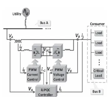
Fig. 1. Example of applicability of iUPQC.
This paper proposes an enhanced controller, which extends the iUPQC functionalities. This enhanced form of iUPQC controller incorporates all functionalities of those past ones, including the voltage direction at the heap side transport, and now giving likewise voltage direction at the matrix side transport, similar to a STATCOM to the framework. Test results are given to approve the new controller plan. This paper is composed in five segments. After this presentation, in Section II, the iUPQC relevance is clarified, and in addition the novel component of the proposed controller. presents the proposed controller and an investigation of the power stream in consistent state. At long last, give the reenactment comes about and the conclusions, individually.
II. EQUIPMENTAPPLICABILITY Displaying OF PROPOSED THEORY
Keeping in mind the end goal to illuminate the pertinence of the enhanced iUPQC controller,Fig. 1depicts an electrical framework with two transports in spotlight, i.e., transport An and transport B. Transport A will be a basic transport of the power framework that provisions delicate loads and fills in as purpose of coupling of a microgrid. Transport B is a transport of the microgrid, where nonlinear burdens are associated, which requires premium-quality power supply. The voltages at transports An and B must be controlled, so as to appropriately supply the touchy burdens and the nonlinear burdens. The impacts brought about by the symphonious streams drawn by the nonlinear burdens ought to be relieved, dodging consonant voltage spread to transport A.
The utilization of a STATCOM to ensure the voltage direction at transport An is insufficient on the grounds that the symphonious streams drawn by the nonlinear burdens are not moderated. Then again, an UPQC or an iUPQC between transport An and transport B can remunerate the symphonious streams of the nonlinear loads and repay the voltage at transport B, as far as voltage sounds, unbalance, and hang/swell. All things considered, this is still insufficient to ensure the voltage control at transport A.
Thus, to accomplish all the craved objectives, a STATCOM at transport An and an UPQC (or an iUPQC)
between transports An and B ought to be utilized. In any case, the expenses of this arrangement would be preposterously high. An alluring arrangement would be the utilization of a changed iUPQC controller to give likewise receptive power support to transport A, notwithstanding every one of those functionalities of this gear, Note that the adjusted iUPQC fills in as an intertie between transports An and B. In addition, the microgrid associated with the transport B could be a mind boggling framework including
FIG.2 Modified iUPQC configuration
a) "savvy" electrical switch as an intertie between the lattice and the microgrid;
b) vitality and power stream control between the framework and the microgrid (forced by a tertiary control layer for the microgrid);
c) responsive power bolster at transport An of the power framework;
d) voltage/recurrence bolster at transport B of the microgrid;
e) consonant voltage and current detachment between transport An and transport B (concurrent network voltage and load-current activefiltering capacity); f) voltage and current irregularity pay.
The functionalities (d)–(f) beforehand recorded were widely clarified and confirmed through recreations and experimentalanalysis while the usefulness (c) includes the first commitment of the present work.depicts,in detail, the associations and estimations of the iUPQC between transport An and transport B. As indicated by the traditional iUPQC controller, the shunt converter forces a controlled sinusoidal voltage at transport B, which relates to the previously mentioned usefulness (d). Thus, the shunt converter has no further level of opportunity as far as repaying dynamic or responsive power factors to grow its usefulness. Then again, the arrangement converter of an ordinary iUPQC utilizes just a dynamic power control variable p, with a specific end goal to integrate an essential sinusoidal
current drawn from transport A, comparing to the dynamic power requested by transport B. On the off chance that the dc connection of the iUPQC has no extensive
vitality stockpiling framework or even no vitality source, the control variable likewise fills in as an extra dynamic power reference to the arrangement converter to keep the vitality inside the dc connection of the iUPQC adjusted. For this situation, the misfortunes in the iUPQC and the dynamic influence provided by the shunt converter must be immediately repaid as an extra dynamic influence infused by the arrangement converter into the transport
B.The iUPQC can fill in as: a) "shrewd" electrical switch and as
b) control stream controller between the network and the microgrid just if the remunerating dynamic and responsive power references
FIG 3.Novel iUPQC controller
provide reactive-power compensation like a STATCOM to the bus A of the grid. As it will be confirmed, this functionality can be added into the controller without degrading all other functionalities of the iUPQC.
III. FUZZY CONTROLLER
The word Fuzzy means dubiousness. FUZZYNESS happens when the limit of snippet of data is not obvious. In 1965 Lotfi A. Zahed propounded the FUZZY set hypothesis. FUZZY set hypothesis displays massive potential for successful explaining of the vulnerability in the issue. FUZZY set hypothesis is a magnificent scientific device to deal with the vulnerability emerging because of ambiguity. Understanding human discourse and perceiving manually written characters are some regular occurrences where FUZZYNESS shows.
FUZZY set hypothesis is an augmentation of traditional set hypothesis where components have shifting degrees of enrollment. FUZZY rationale utilizes the entire interim in the vicinity of 0 and 1 to portray human thinking. In FLC the info factors are mapped by sets of enrollment capacities and these are called as "FUZZY SETS".
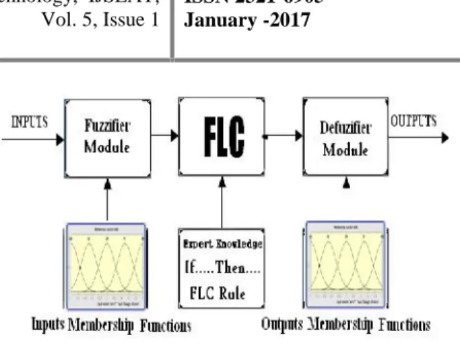
FUZZY set contains from an enrollment capacity which could be characterizes by parameters. The incentive in the vicinity of 0 and 1 uncovers a level of enrollment to the FUZZY set. The way toward changing over the fresh contribution to a FUZZY esteem is called as "fuzzificaton." The yield of the Fuzzier module is interfaced with the tenets. The fundamental operation of FLC is developed from FUZZY control rules using the estimations of FUZZY sets when all is said in done for the blunder and the change of mistake and control activity. Fundamental FUZZY module is appeared in fig.6. The outcomes are joined to give a fresh yield controlling the yield variable and this procedure is called as "DEFUZZIFICATION."
Fig.IIIa. Fuzzy Basic Module
Fuzzy rules
In the fuzzy control, input and output variables are the size of the form to describe in words, so to select special vocabulary to describe these variables, generally used in "big, medium and small" Three words to express the controller input and output variables state, plus the positive and negative directions, and zero, a total of seven words : { negative big, negative medium, negative small, zero, positive small, middle, CT } , the general terms used in the English abbreviation prefix : {NB , NM, NS , ZE, PS , PM, PB}.
COE E
NB NM NS ZE PS PM PB
NB NB NB NB NB NM NS ZE
NM NB NB NB NM NS ZE PS
NS NB NM NS NS ZE PS PM
ZE NB NM NS ZE PB NS ZE
PS NM NS ZE PS PM PM PB
PM NS ZE PS PM PB PB PB
PB ZE PS PM PB PB PB PB
IV.SIMULINK MODELLING AND RESULTS
FIG4:Simulink Block Diagram
The improved iUPQC controller, as shown inFig. 3,was verified in a 5-kVA prototype, whose parameters are presented in Table I. The controller was embedded in a fixed-point digital signal processor (TMS320F2812). In order to verify all the power quality issues described in this paper, the iUPQC was connected to a grid with a voltage sag system, as depicted . The voltage sag system was composed by an inductor (LS), a resistor (RrmSag), and a breaker(SSag).
FIG5:Control Block Diagram
To cause a voltage sag at bus A,SSagis closed. At first, the source voltage regulation was tested with no load
connected to bus B. In this case, the iUPQC behaves as a STATCOM, and the breakerSSagis closed to cause the voltage sag. To verify the grid-voltage regulation (seeFig. 6), the control of theQSTATCOM variable is enabled to compose (4) at instantt=0s. In
this experimental case,LS=10mH, andRSag=7.5Ω.
Before the QSTATCOM variable is enabled, only the dc link and the voltage at bus B are regulated, and there is a voltage sag at bus A, as shown inFig. 7.Aftert=0s, the iUPQC starts to draw reactive current from bus A, increasing the voltage until its reference value. As shown inFig. 6, the load voltage at bus B is maintained regulated during all the time, and the grid-voltage regulation of bus A has a fast response.
FIG.6 iUPQC response at no load conditions : a) Grid voltages b)load voltages and c)grid currents
FIG.7 iUPQC transitory response during the connection of a three phase diode rectifier: (a) load
Next, the experimental case was carried out to verify the iUPQC performance during the connection of a nonlinear load with the iUPQC already in operation. The load is a three phase diode rectifier with a
seriesRLload at the dc link (R=45ΩandL=22mH), and
the circuit breaker S Sag is permanently closed, with
aLS=10mH and aRSag=15Ω. In this way, the voltage -sag disturbance is increased due to the load connection. InFig. 8, it is possible to verify that the iUPQC is able to regulate the voltages at both sides of the iUPQC, simultaneously. Even after the load connection, att=0s, the voltages are still regulated, and the currents drawn from bus A
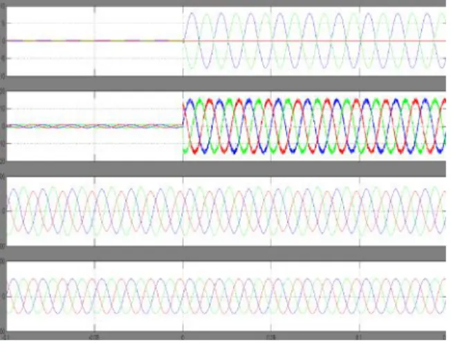
Fig. 8. iUPQC transitory response during the connection of a two phase diode rectifier: (a) load currents, (b) source currents, (c) loadvoltages, and (c)
source voltages.
are almost sinusoidal. Hence, the iUPQC can perform all the power-quality compensations, as mentioned before, including the grid-voltage regulation. It is important to highlight that the grid-voltage regulation is also achieved by means of the improved iUPQC controller, as introduced in Section III. Finally, the same procedure was performed with the connection of a two-phase diode rectifier, in order to better verify the mitigation of power quality issues. The diode rectifier
has the same dc load (R=45ΩandL=22mH) and the same voltage sag (LS=10mH andRrmSag=15Ω).Fig.
9depicts the transitory response of the load connection. Despite the twophase load currents, after the load connection att=0s, the three-phase current drained from the grid has a reduced unbalanced component. Likewise, the unbalance in the voltage at bus A is negligible. Unfortunately, the voltage at bus B has higher unbalance content. These components could be mitigated if the shunt compensator works as an ideal
voltage source, i.e., if the filter inductor could be eliminated. In this case, the unbalanced current of the load could be supplied by the shunt converter, and the voltage at the bus B could be exactly the voltage synthesized by the shunt converter. Therefore, without filter inductor, there would be no unbalance voltage drop in it and the voltage at bus B would remain balanced. However, in a practical case, this inductor cannot be eliminated, and an improved PWM control to compensate voltage unbalances.
V. CONCLUSION
In the improved iUPQC controller, the currents synthesized by the series converter are determined by the average activepower of the load and the active power to provide the dc-link voltage regulation, together with an average reactive power to regulate the grid-bus voltage. In this manner, in addition to all the power-quality compensation features of a conventional UPQC or an iUPQC, this improved controller also mimics a STATCOM to the grid bus. This new feature enhances the applicability of the iUPQC and provides new solutions in future scenarios involving smart grids and microgrids, including distributed generation and energy storage systems to better deal with the inherent variability of renewable resources such as solar and wind power. Moreover, the improved iUPQC controller may justify the costs and promotes the iUPQC applicability in power quality issues of critical systems,a fuzzy controller is implemented in this project in the place of PI controller, where it is necessary not only an iUPQC or a STATCOM, but both, simultaneously. Despite the addition of one more power-quality compensation feature, the grid-voltage regulation reduces the inner-loop circulating power inside the iUPQC, which would allow lower power rating for the series converter.
The simulation results verified the improved iUPQC goals. The grid-voltage regulation was achieved with no load, as well as when supplying a three-phase nonlinear load. These results have demonstrated a suitable performance of voltage regulationat both sides of the iUPQC, even while compensating harmonic current and voltage imbalances.
REFERENCES
Additional Grid-Voltage Regulation as a STATCOM ” IEEE TRANSACTIONS ON INDUSTRIAL ELECTRONICS, VOL. 62, NO. 3, MARCH 2015.
[2]K.Karanki,G.Geddada,M.K.Mishra,andB.K.Kumar,
“Amodified three-phase four-wire UPQC topology with reduced DC-link voltage rating,”IEEE Trans. Ind.
Electron., vol. 60, no. 9, pp. 3555–3566, Sep. 2013.
[3] V. Khadkikar and A. Chandra, “A new control
philosophy for a unified power quality conditioner (UPQC) to coordinate load-reactive power demand
between shunt and series inverters,”IEEE Trans.
Power Del., vol. 23, no. 4, pp. 2522–2534, Oct. 2008.
[4] K. H. Kwan, P. L. So, and Y. C. Chu, “An output
regulation-based unified power quality conditioner
with Kalman filters,”IEEE Trans. Ind.Electron., vol. 59, no. 11, pp. 4248–4262, Nov. 2012.
[5] A. Mokhtatpour and H. A. Shayanfar, “Power
quality compensation as well as power flow control
using of unified power quality conditioner,” in Proc.
APPEEC, 2011, pp. 1–4.
[6] J. A. Munozet al., “Design of a discrete-time linear
control strategy for a multicell UPQC,”IEEE Trans.
Ind. Electron., vol. 59, no. 10, pp. 3797–3807, Oct. 2012.
[7] V. Khadkikar and A. Chandra, “UPQC-S: A novel concept of simultaneous voltage sag/swell and load reactive power compensations utilizingseries inverter
of UPQC,”IEEE Trans. Power Electron., vol. 26, no.
9, pp. 2414–2425, Sep. 2011.
[8] V. Khadkikar, “Enhancing electric power quality using UPQC: A comprehensive overview,”IEEE
Trans. Power Electron., vol. 27, no. 5, pp. 2284–2297, May 2012.
[9] N. Voraphonpiput and S. Chatratana, “STATCOM
analysis and controller design for power system
voltage regulation,” in Proc. IEEE/PES Transmiss.