Global Journal of Advance Engineering Technologies and Sciences
MIMO-STBSC SYSTEM WITHOUT OPTICAL LINK
Mridu Jain
1, Ritu Dubey
2Scholar-M-Tech, Asst. Prof. in E&C Deptt.
B.T.I.R.T.
Sagar, India.
[email protected]
ABSTRACT
Multi-carrier modulation is an attractive technique for fourth generation wireless communication. That information the undesired effects occurring to the distortion techniques can be alleviated with the penalty of the reduced transmission and receiving rates due to introduction of redundancy.
MIMO consist of large number of independent subcarriers, MIMO has been widely used in communication systems to meet the demand for increasing data rates. It is robust over multipath fading channels and results in significant reduction of the transceiver complexity. However, one of its disadvantages is sensitivity to carrier frequency offset which causes attenuation, rotation of subcarriers, ISI, CE.
MIMO is used for Trans-receive system for increase the channel capacity where the suitable number of antennas is required. Along with OFDM-MIMO with STBCS is considered for wideband transmission to reduced the inter symbol interference ISI and problem of channel estimation CE for fading channels to enhance system capacity, Whereas OFDM-MIMO communication has a number of benefits for instance larger bandwidth, reduced power utilization that has made it an gorgeous accomplishment decision for different communication systems including wireless LAN’s. Proposed work investigate the possibility of MIMO technique STBCS based system i.e. MIMO- STBCS for wireless communication. It reduced the problem of MIMO improving bit error rate BER, and system capacity this work implementation on 2x2 & 4x4 MIMO communications.
Keywords: Space Time Block Coding Scheme STBCS, Channel Estimation CE, Inter Symbol Interference ISI, Single-Input Single-Output (SISO), Multiple-Single-Input Multiple-Output (MIMO), Analog to-Digital Convertors (ADCs), Orthogonal Frequency Division Multiplexing (OFDM). Component; formatting; style; styling; insert (key words)
INTRODUCTION
Speedy broadband Internet admittance is broadly accepted as a catalyst to economic growth and social equity in Australia and around the world. The Australian Government has therefore commenced the construction of the National Broadband Network (NBN) to deliver the best and most cost effective infrastructure across Australia [10]. However, rural Australia's inherent dispersed population over a large geographical area makes delivery of efficient, well-maintained and cost-effective Internet access a challenging task. Therefore, the Commonwealth Scientific and Industrial Research Organization (CSIRO) has proposed and implemented a novel and feasible system called the wireless broadband access" system, which is an efficient multi-user single-antenna multiple-input multiple-output (MUSA-MIMO) wireless communications technology as a practical solution to provide cheaper and faster Internet services to rural areas in a spectrally efficient and cost effective manner [11].
The advancement of multicarrier orthogonal frequency division multiplexing (OFDM) [12] technology with multiple-input multiple-output (MIMO) MIMO) [13] systems stand as promising technologies to address bottlenecks in the traffic capability of present and upcoming high data rate in wireless communications
antenna or multiple antennas used to all together serve up each user in a cell through high data rates, moreover a broad frequency spectrum or an excess of contact points would be necessary. Therefore, the CSIRO has proposed and implemented a novel and feasible system called the wireless broadband access" system [17].
This system uses point-to-multi-point wireless communications technology with multiple users (multi-user MIMO) and has been implemented using OFDM. This system employs the space division multiple access (SDMA) technique to allow users to employ the same frequency at the same time. This approach facilitates the allocation of a wide frequency bandwidth for each user, thus giving them access to faster data rates [18]. However, this novel system did not have a proper channel tracking algorithm. Therefore, our research aimed to develop a novel channel tracking algorithm that suit this novel system. Moreover, we received financial support from the Queensland Government under the Smart Future Fellowship Scheme to conduct this research. The present research is based on this wireless broadband access system and focuses on the case of six users with a 12 AP antenna system, as implemented in [19]. However, the proposed methods are applicable to a larger number of users and antennas. The multiple paths in a channel represent the effect of multiple wave fronts. The channel is said to be time-varying, when the transmitter or the receiver is mobile or the channel is rapidly changing due to environmental conditions. Identifying the information about the channel is important in order to recover the transmitted signal at the receiver under these channel conditions. This phenomenon is referred to as channel estimation. The removal of channel effects is referred to as equalization. Channel tracking performs an important task to track a time-varying channel even after the initial channel estimation. The motivation of the study presented in this thesis is to develop channel tracking algorithm that can based multi-user MIMO-OFDM communication system developed by CSIRO.
BASIC OF MIMO
MIMO-OFDM is a technology that combines MIMO and OFDM both to transmit data in wireless communications in order to deal with frequency selective channel outcome. The OFDM signal on every subcarrier be able to beat narrowband fading, therefore, OFDM can transform frequency-selective fading channels into parallel level ones. Then by combine MIMO and OFDM technology mutually, MIMO algorithms can be apply in broadband transmission [22].
A MIMO OFDM system transmits data modulated by OFDM from multiple antennas at once. At the receiver, after OFDM demodulation, the signal are improved by decoding each the sub-channels from all the transmit antennas [23].
Fig.The Basic Structure of MIMO with Configurations
MIMO OFDM resolve permit restore providers to organize a Broadband Wireless Access (BWA) system that has Non-Line-of-Sight (NLOS) functionality. Specially, MIMO-OFDM takesbenefit of the multipath property of environment with base station antennas that do not have LOS. By combine mutual techniques, MIMO-OFDM can propose equally robustness and high throughput. In a multiuser development where many users communicate with a central station (base station or access point), MIMO-OFDM become yet extra tempting because it provide an extra opportunity to develop due to a lot of users.
Diversity is used in MIMO to combat channel fading. Since in MIMO each pair of transmitting and receiving antennas provides a signal path from the transmitter to the receiver and each path carry the same information simultaneously, the signal achieved in the receive antenna is more reliable and the fading can be effectively decreased. If the path gains between individual transmit– receive antenna pairs fade independently, in this case multiple parallel spatial channels are created. By transmitting independent information streams in parallel through the spatial channels, the data rate can be increased. This effect is also called spatial multiplexing [21].
So the benefit of diversity is lower error probability and the benefit of multiplexing is higher rate though the difference between them is that the requirement of diversity is sending the same information and the requirement of multiplexing is send independent information. Obviously, the conflicts between the two suggest fundamental tradeoff between benefits obtained from diversity and multiplexing.
PROBLEM IN MIMO SYATEM
Fig. Frequency Selective Fading as a Function of Delay Spread
Fast Fading: Occurs due to Doppler spread. The rate of change of the channel characteristics is larger than the rate of change of the transmitted signal. As s result, the channel changes during a symbol period. The channel changes because of relative motion between the receiver and the baseband signaling. Coherence time (Tc) of the channel is smaller than the symbol period (Ts) of the transmitted signal.
Fig. Fast Fading as a Function of Doppler Spread
Slow Fading: Rate of change of the channel characteristics is much smaller than the rate of change of the transmitted signal. The channel may be assumed static over one or several reciprocal bandwidth intervals. In frequency domain, this means that Doppler Spread of channel is much smaller than the bandwidth of baseband signal. Velocity of the mobile (or the velocity of objects in the channel) and the baseband signaling determines whether a signal undergoes fast fading or slow fading.
Fig. Slow Fading as a Function of Doppler Spread
At lower values of coherence time and delay spread, the channel variation is fast and the type of fading flat, hence no ISI. At lower value of coherence time and as the delay spread increases, the fading becomes frequency-selective, which leads to ISI. At higher values of coherence time and lower values of delay spread, the channel variation is slow and the fading is flat, hence there is no ISI. At higher values of coherence time and delay spread, the fading becomes frequency-selective, which causes ISI.
Rayleigh Fading: When the spatial distance between antennas and angular spreading is large enough, the channel coefficients are assumed to be uncorrelated. Also, if all the channel elements have the same average power, then the correlation matrix is proportional to unity. In this case, the complex fading coefficients hi,j ’s
are assumed to be a zero-mean unit variance complex Gaussian random variable with independent real and imaginary parts. Equivalently, hi,j’s have uniform phase
and Rayleigh amplitude. However, as it is pointed out in [19], limited angular spread and limited distance between antennas cause the channels become correlated. Furthermore, if there is a strong LOS component, the channel statistics become RICIAN distributed. In addition, the use of polarization diversity creates gain imbalances between elements of the MIMO channel matrix since the vertical and horizontal polarizations have different propagation characteristics.
average signal power is normalized to unity, the pdf of the RICIAN distribution is given as [21],
p(a) = 2a(1 + K)e−K−(1+K)a2I0(2a√K(K+1)) a ≥ 0 (3.5)
Where I0 is the modified Bessel function of the first kind and zero order and K is the RICIAN factor which denotes the power ratio of the direct and scattered signal components. For K = 0 RICIAN distribution becomes the Rayleigh distribution.
PROPOSED METHOD
The technique proposed is a simple transmit diversity scheme which improves the signal quality at the receiver
on one side of the link by simple processing across two transmit antennas on the opposite side. The obtained diversity order is equal to applying maximal-ratio receiver combining (MRRC) with two antennas at the receiver. The scheme may easily be generalized to two transmit antennas and M receive antennas to provide a diversity order of 2M. This is done without any feedback from the receiver to the transmitter and with small computation complexity.
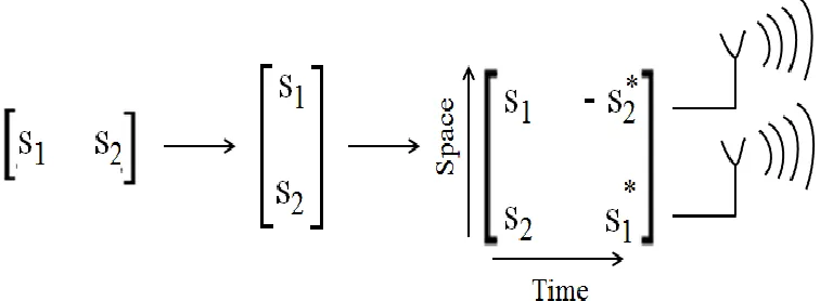
Fig. Space-Time Coding Scheme
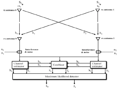
The Encoding and Transmission Sequence: At a given symbol period, two signals are simultaneously transmitted from the two antennas. The signal transmitted from antenna zero is denoted by S1 and from antenna one by S2. During the next symbol period signal (- S2*) is transmitted from antenna zero, and signal (S1*)
is transmitted from antenna one where * is the complex conjugate operation. This sequence is shown in Fig.3.11 the encoding is done in space and time (space–time coding). The encoding, however, may also be done in space and frequency. Instead of two adjacent symbol periods, two adjacent carriers may be used (space– frequency coding).
The channel at time t may be modeled by a complex multiplicative distortion h0 (t) for transmit antenna zero and h1(t) for transmit antenna one. Assuming that fading is constant across two consecutive symbols, we can write
Where T is the symbol duration. The received signals can then be expressed as
Where r0and r1 are the received signals at time t and t+T and n0 and n1are complex random variables representing receiver
noise and interference.
The Combining Scheme: The combiner shown in Fig.3.11 builds the following two combined signals that are sent to the maximum likelihood detectors:
Substituting (3.9) and (3.10) into (3.11), we get
The Maximum Likelihood Decision Rule: These combined signals are then sent to the maximum likelihood detector. The resulting combined signals in are equivalent to that obtained from two-branch MRRC. Therefore, the resulting diversity order from the new two-branch transmit diversity scheme with one receiver is equal to that of two-branch MRRC.
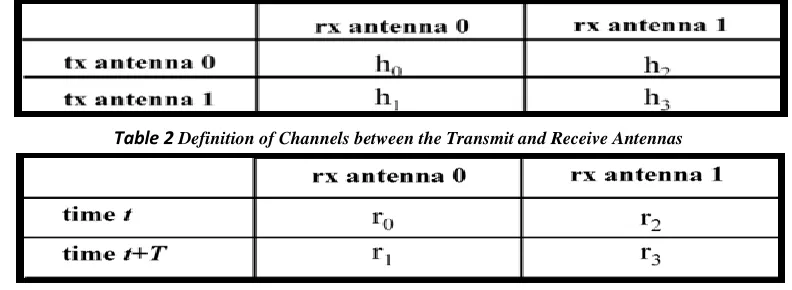
Table 2 Definition of Channels between the Transmit and Receive Antennas
Table 3 Notation for the Received Signals At The Two Receive Antennas
Fig. shows the baseband representation of the new scheme with two transmits and two receive antennas. The encoding and transmission sequence of the information symbols for this configuration is identical to the case of a single receiver, shown in Fig. defines the channels between the transmit and receive antennas, defines the notation for the received signal at the two receive antennas, where
Where n0 n1 n2 and n3 are complex random variables representing receiver thermal noise and interference. The combiner in
Fig. builds the following two signals that are sent to the maximum likelihood detector:
Substituting the appropriate equations we have
These combined signals are then sent to the maximum likelihood decoder which for signal s0 uses the following decision
criteria.
The combined signals in are equivalent to that of four-branch MRRC. Therefore, the resulting diversity order from the new two-branch transmit diversity scheme with two receivers is equal to that of the four-branch MRRC scheme.
CHANNEL ESTIMATION & DETECTION
Channel estimation is done to obtain Channel State Information (CSI). CSI refers to known channel properties of a communication link. This information describes how a signal propagates from the transmitter to the receiver and represents the combined effect of
scattering, fading, and power decay with path length. The efficacy of detection process at the receiver depends on the accuracy of CSI.
SPATIAL MULTIPLEXING CODING
SCHEME (SMCS)
Fig. Spatial Multiplexing With Serial Encoding
With serial encoding, the bit stream is temporally encoded over the channel block length T to form the codeword [x1,xT]. The codeword is interleaved and mapped to a constellation point, then de-multiplexed onto the different antennas. The first Mt symbols are transmitted from the Mt antennas over the first symbol time, and this process continues until the entire codeword
has been transmitted. We denote the symbol sent over the kth antenna at time i as xk[i]. If a codeword is sufficiently long, it is transmitted over all Mt transmit antennas and received by all Mr receive antennas, resulting in full diversity gain. However, the codeword length T required to achieve this full diversity is Mt, Mr and decoding complexity makes serial encoding impractical.
Fig. Spatial Multiplexing With Parallel Encoding
A simpler method to achieve spatial multiplexing, pioneered at Bell Laboratories as one of Bell Labs Layered Space Time architectures for MIMO channels, is parallel encoding, illustrated in Fig.. With parallel encoding the data stream is de-multiplexed into Mt
independent streams. Each of the resulting sub streams is passed through an SISO temporal encoder with block length T, interleaved, mapped to a signal constellation point, and transmitted over its corresponding transmit antenna.
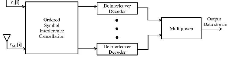
Fig. Receiver with Linear Complexity
However, optimal decoding still requires joint detection of the code words from each of the transmit antennas, since all transmitted symbols are received by all the receive antennas. The receiver complexity can be significantly reduced through the use of symbol interference cancellation, as shown in Fig. This
Fig. Diagonal Encoding with Stream Rotation
However, rather than transmitting each codeword with one antenna, the codeword symbols are rotated across antennas, so that a codeword is transmitted by all Mt
antennas. The operation of the stream rotation is shown in Fig.
Fig. Stream Rotation
Suppose the ith encoder generates the codeword xi = [xi[1],… xi[T]]. The stream rotator transmits each symbol on a different antenna, so xi[1] is sent on antenna 1 over symbol time i, xi[2] is sent on antenna 2 over
symbol time i +1, and so forth. If the code block length T exceeds Mt then the rotation begins again on antenna 1. As a result, the codeword is spread across all spatial dimensions.
RESULT AND SIMULATION
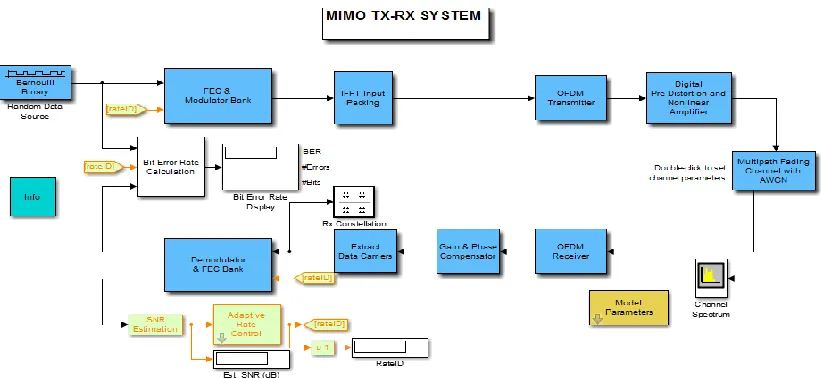
Fig. GUI Model of Proposed System MIMO
In our work, we consider, 2x2, 4x4 MIMO link with STBCS as sketched in Fig.4.1 As mentioned earlier, deep fades are equivalent to burst errors. These can be dispersed into random errors using an interleaver. Hence, we use SMCS as the coding techniques, each
improve the error performance. To investigate the effect of adding redundancy, we have considered different code rates for both codes. The performance of various code rates are also compared with encoded scheme. Higher code rates of STBCS are obtained by considering puncturing technique. The error performance also depends on the type of modulation scheme implemented. We have chosen QAM. The two parameters by which these two schemes differ are bandwidth efficiency and the distance between the symbols on the signal space (constellation). As the order of the modulation increases, the signal space becomes narrower. Thus higher order modulation schemes are more flat to fading. However, there should be a tradeoff between the bandwidth efficiency and error performance. This analysis will help in identifying the suitable modulation scheme for a particular application. We study the performance in the presence of Rician fading distributions that represent multiple reflectors and scatterers and, in the case of Rician, includes dominant line of sight components. The product of path delay with signal bandwidth determines the type of fading, i.e., whether flat or
frequency-selective. In our case, this product is greater than 0.1 making the fading to be frequency-selective. The channel is taken to be an Additive White Gaussian Noise (AWGN) channel and vary Eb/No values At the receiving end, the process involved are channel estimation, coherently combining signals from multiple antennas, followed by demodulation, random de-interleaving and then soft decoding. Simulation of a complete 2x2, 4x4 MIMO STBCS wireless communication link is done in MATLAB. The schemes of a MIMO link considered for error performance analysis are MIMO SMCS for RICIAN channel.
RESULTS AND PARAMETERS
Table 4 Parameter used in this work
It is interesting to note that in both the plots on many occasions all the four channels fade together. But, they deep fade together rarely demonstrating diversity. This means complete data loss is rare and channel codes may help improve performance.
The graphs of IFFT transmit signal with 256 in fig11, 512 in fig.12 point for modulation. Fig13 shows the QAM demapped point of receiving site.In fig.14 shows the Pre Distortion of Amplifier Input Output with Amplitude Comparison and fig shows the Pre Distortion of Amplifier Input Output with Phase Difference Comparison.
Fig. Antenna Power for MIMO IFFT 512.
Fig. MIMO Rx 128 QAM Point De-Mapping
Fig. Pre Distortion of Amplifier Input Output with Phase Difference Comparison
Now these both graph shows the bit error performance of MIMO 2x2 in fig.16 and 4x4 in fig. 17 channel there is also comparison with or without STBCS method.
Fig. 4x4 MIMO channel
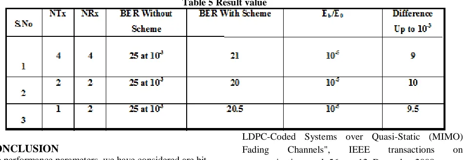
Table 5 Result value
CONCLUSION
The performance parameters, we have considered are bit error rate, code rate and coding gain. We have carried out simulations of a complete wireless communication MIMO link by considering Hamming and Convolution codes, BPSK, QAM and QPSK modulation schemes under RICIAN fading environment. We have presented the BER vs Eb/No and BER vs code rate plots for the above mentioned schemes. From the simulation results, it is observed that, coding does improve the error performance, but Eb/No has dominant role than the code rate in error recovery. With RICIAN frequency selective fading, the number of and delay in multiple paths increases, this leads to Inter Symbol Interference (ISI). The importance of error control coding techniques for MIMO fading channel has been studied. Wireless multipath fading channel, various coding schemes and MIMO have also been studied. From literature survey, it is observed that, by considering various coding schemes, under different fading environment, significant enhancement in bit error performance and coding gain can be achieved. Hence we set our goal to analyze the performance of various coding schemes under MIMO fading environment. The MIMO- STBCS technology is best suited for mitigating ISI and CE in RICIAN fading channel. In our future work we will analyze the error performance of various coding techniques and modulation schemes in the presence of RAYLEIGH and RICIAN fading channels by employing MIMO- STBCS technique.
REFERENCES
1. Andreas F.Molish, „Wireless Communication‟, Second Edition, John Wiley & Sons Ltd, 2011.
2. Wei Ning An,Walaa Hamouda, Senior Member of IEEE, “Reduced Complexity
Concatenated code in Fading Channels,” IEEE Communication Letter, vol. 15, no. 7, July 2011. 3. Jingqiao Zhang, Student Member, IEEE, and Heung-No Lee, Member, IEEE, " Performance Analysis on
LDPC-Coded Systems over Quasi-Static (MIMO) Fading Channels", IEEE transactions on communications, vol. 56, no. 12, December 2008.
4. Fulvio Babich, Senior Member, IEEE,‟On the Performance of Efficient Coding Techniques over Fading Channels‟, IEEE Transactions on Wireless Communications, Vol.3, No.1, January 2004.
5. Andre Neubauer, Jurgen Freudenberger, Volker Kuhn, „ Coding Theory – Algorithms, Architectures, and Applications‟, WILEY-INDIA edition.
6. Simon Haykin, 'Digital Communications', John Wiley & Sons Ltd, edition-2006.
7. Theodore S.Rappaport, ‟Wireless Communications – Principles and Practice‟, Pearson second edition. 8. Gregory D. Durgin, „Space-Time Wireless Channels‟, Prentice Hall, 2002.
9. Arogyaswami Paulraj,Rohit Nabar, Dhananjay Gore,‟Introduction to Space-Time Wireless Communications‟, Cambridge University press – 2008. 10. Andrea Goldsmith, ‟Wirelss Communications‟, Cambridge University press – 2005.
11. R. D. Murch and K. B. Letaief, "Antenna systems for broadband wireless access," IEEE Communications Magazine, vol. 40, pp. 76-83, 2002.
12. S. P. Alex and L. M. A. Jalloul, "Performance Evaluation of MIMO in IEEE802.16e/WiMAX," IEEE Journal of Selected Topics in Signal Processing, vol. 2, pp. 181-190, 2008.
13 Z. Kan, H. Lin, L. Gang, C. Hanwen, W. Wang and M. Dohler, "Beyond 3G Evolution," IEEE Vehicular Technology Magazine, vol. 3, pp. 30-36, 2008.
15. J. Ming and L. Hanzo, "Multiuser MIMO-OFDM for Next-Generation Wireless Systems," Proceedings of the IEEE, vol. 95, pp. 1430-1469, 2007.
16. D. Agrawal, V. Tarokh, A. Naguib and N. Seshadri, "Space-time coded OFDM for high data-rate wireless communication over wideband channels," in IEEE Conference on Vehicular Technology, vol.3, pp. 2232-2236, 1998.
17 M. Uysal, N. Al-Dhahir and C. N. Georghiades, "A space-time block-coded OFDM scheme for unknown frequency-selective fading channels," IEEE Communications Letters , vol. 5, pp. 393-395, 2001. 18 H. Bolcskei and A. J. Paulraj, "Space-frequency coded broadband OFDM systems," in IEEE Conference on Wireless Communications and Networking, vol.1, pp. 1-6, 2000.
19 H. El Gamal, A. R. Hammons, L. Youjian, M. P. Fitz and O. Y. Takeshita, "On the design of space-time and space-frequency codes for MIMO frequency-selective fading channels," IEEE Transactions on Information Theory, vol. 49, pp. 2277-2292, 2003.
20 W. Su, Z. Safar and K. J. R. Liu, "Full-rate full-diversity space-frequency codes with optimum coding advantage," IEEE Transactions on Information Theory, vol. 51, pp. 229-249, 2005.
21. L. Keonkook, K. Youngok, K. Joonhyuk, "A novel orthogonal space-time-frequency block code for OFDM systems," IEEE Communications Letters, vol. 13, pp. 652-654, 2009.
22. M. Fozunbal, S. W. McLaughlin and R. W. Schafer, "On space-time-frequency coding over MIMO-OFDM systems," IEEE Transactions on Wireless Communications, vol. 4, pp. 320-331, 2005.
23. D. Astely, E. Dahlman, A. Furuskar, Y. Jading, M. Lindstrom and S. Parkvall, "LTE: the evolution of mobile broadband - [LTE part II: 3GPP release 8]," IEEE Communications Magazine, vol. 47, pp. 44-51, 2009. 24. L. Hun-Hee, B. Myung-Sun, K. Jee-Hoon and S. Hyoung-Kyu, "Efficient detection scheme in MIMO-OFDM for high speed wireless home network system," , IEEE Transactions on Consumer Electronics, vol. 55, pp. 507-512, 2009.
25. N. Sarmadi, S. Shahbazpanahi and A. B. Gershman, "Blind Channel Estimation in Orthogonally Coded MIMO-OFDM Systems: A Semidefinite Relaxation Approach," , IEEE Transactions on Signal Processing, vol. 57, pp. 2354-2364, 2009.
26. Z. Jian-Kang and M. Wing-Kin, "Full Diversity Blind Alamouti Space-Time Block Codes for Unique
Identification of Flat-Fading Channels," IEEE Transactions on Signal Processing , vol. 57, pp. 635-644, 2009.
27. W. Feng, W. P. Zhu and M. N. S. Swamy, "A Semiblind Channel Estimation Approach for MIMO-OFDM Systems," IEEE Transactions on Signal Processing, vol. 56, pp. 2821-2834, 2008.
28. F. Delestre and Y. Sun, "MIMO-OFDM with pilot-aided channel estimation for WiMax systems," in IEEE 6th International Conference on Wireless and Mobile Computing, Networking and Communications, pp. 586-590, 2010.