Light-Emitting Electrochemical Cells and Solution-Processed Organic
Light-Emitting Diodes Using Small Molecule Organic Thermally
Activated Delayed Fluorescence Emitters
Michael Y. Wong,
†Gordon J. Hedley,
‡Guohua Xie,
‡Lisa S. Ko
̈
lln,
‡Ifor D. W. Samuel,
‡Antonio Pertega
s,
́
§Henk J. Bolink,
§and Eli Zysman-Colman
*
,††Organic Semiconductor Centre, EaStCHEM School of Chemistry, University of St Andrews, St Andrews, Fife KY16 9ST, U.K. ‡Organic Semiconductor Centre, SUPA, School of Physics and Astronomy, University of St Andrews, North Haugh, St Andrews, Fife
KY16 9SS, U.K.
§Instituto de Ciencia Molecular, Universidad de Valencia, Catedratico José ́Beltran 2, Paterna E-46980, Spaiń
*
S Supporting InformationABSTRACT: Two novel charged organic thermally activated delayed
fluorescence (TADF) emitters, 1 and 2, have been synthesized. Their TADF behavior is well-supported by the multiexponential decay of their emission (nanosecond and microsecond components) and the oxygen dependence of the photoluminescence quantum yields. Spin-coated electroluminescent devices have been fabricated to make light-emitting electrochemical cells (LEECs) and organic light-emitting diodes (OLEDs). Thefirst example of a non-doped charged small organic molecule LEEC is reported and exhibited an external quantum efficiency (EQE) of 0.39% using2. With a multilayer architecture, a solution-processed OLED device using neat 2 as the emitting layer gave an EQE of 5.1%, the highest reported to date for a nondoped solution-processed small molecule organic TADF OLED. These promising results open up a new area in light-emitting materials for the development of low-cost TADF LEECs.
■
INTRODUCTIONOrganic light-emitting diodes (OLEDs) have come to the fore as state-of-the-art technology for visual displays and lighting.1−4 OLEDs are desirable as they are lightweight and flexible, provide better contrast, and possess a large viewing angle.4 OLEDs are also more power efficient than traditional lighting sources, and thus, their wide adoption can alleviate significantly the strain on current energy demand because lighting alone constitutes∼20% of electricity consumption worldwide.5 The
“first-generation” OLEDs were based on organic fluorescent emitters whose efficiency was intrinsically capped at 25% due to only being able to recruit singlet excitons.6 The “ second-generation” OLEDs employed organometallic phosphorescent emitters, which harvest both singlet and triplet excitons for emission due to the enhanced intersystem crossing (ISC) mediated by the large spin−orbit coupling of the heavy metals such as iridium(III) and platinum(II).7−9Despite their highly desirable performance characteristics, the rarity of these metals, their high cost, and their toxicity are important detracting features that inhibit large-scale, worldwide adoption of OLED technology, particularly for lighting applications. “ Third-generation”OLEDs were recently reported by Adachi and co-workers. His group demonstrated how small organic molecules, emitting via a thermally activated delayedfluorescence (TADF) mechanism,10could be integrated into OLEDs and exhibit very
high efficiencies as, like with phosphorescent emitters, both singlet and triplet excitons are recruited for emission.11−14 Thus, TADF-based OLEDs address the key detracting features endemic to second-generation OLEDs while retaining their advantages.15
The principle of TADF relies on a small energy gap between the singlet and triplet excited states (ΔEST). Under these conditions, the excitons in the triplet state can return to the singlet state by reverse intersystem crossing (RISC) using thermal energy, followed by radiativefluorescence.11The small
ΔEST is realized by spatial separation between HOMO and LUMO to minimize the exchange integrals between the two orbitals.16A large number of organic TADF emitters have been reported to date, and the majority of them are based on a twisted intramolecular charge transfer (TICT) design in which the donor and acceptor moieties are designed to be nearly orthogonal to each other.11,13,17,18
Despite this important paradigm shift in emitter design, current OLEDs, including TADF OLEDs, still employ air sensitive electrodes requiring rigorous encapsulation, are usually vacuum deposited, and possess a complex multilayer
Received: May 2, 2015 Revised: September 14, 2015 Published: September 14, 2015
Article
architecture that adds to the cost of fabrication. Single-layer solid-state light-emitting electrochemical cells (LEECs) have received much recent attention for their potential to address these negative features of OLEDs.19−22The emitters in LEECs are frequently ionic transition metal complexes (iTMCs), the most popular and highest-performing class of which are cationic iridium(III) complexes.23,24Without a similar paradigm shift in emitter design coupled with improved device performance characteristics, LEECs will suffer a worse fate than second-generation OLEDs, and this promising technology will be relegated to academic inquiry. Recently, Bolink and co-workers demonstrated thefirst example of an operational LEEC with a small molecule charged organic cyanine-based fluorophore,25 while Edman showed how a small molecule neutral organic
fluorophore can be used as a dopant in LEECs.26 We now report the first example of an organic TADF-based LEEC wherein the TADF material serves the dual role of charge transporter and emitter. Additionally, we also report doped and single-component spin-coated OLEDs, whose external
quan-tum efficiencies are superior to those few previous reports of nondoped TADF OLEDs in the literature,17,27,28and contrast their performance to that of the LEEC.
Small molecule emitters must be charged to mediate charge transport in a single-layer LEEC. We thus set about incorporating tethered imidazolium units onto anN -carbazoyl-dicyanobenzene scaffold first reported by Adachi11 to build charged analogues, 1 and 2, whose synthesis is illustrated in Scheme 1.
The preparation of 3-bromocarbazole3 using N -bromosuc-cinimide29was contaminated by some starting material and 3,6-dibromocarbazole, both of which could be removed by fractional recrystallization from toluene. The preparation of5 was accomplished in good yield by dropwise introduction of the lithiated TBDMS-protected 3-bromocarbazole 4 intermediate to excess 1,4-diiodobutane. Compound6was obtained by SN2 reaction of sodium imidazolate with 5 followed by silyl deprotection using sodium hydride in a one-pot fashion.30 Compounds 7 and 8 were synthesized by reacting 6 with Scheme 1. Synthesis of the Charged TADF Emitters for LEECs 1 and 2a
aConditions: (a) NBS, MeCN, room temperature, 1 h; (b) (i) NaH, THF, room temperature, 30 min, (ii) TBDMSCl; (c) (i)n-BuLi, THF,−78°C,
30 min, (ii) excess 1,4-diiodobutane; (d) NaH, imidazole, THF, reflux, 4 h; (e) (i) NaH,6, THF, room temperature, 30 min, (ii) 2 equiv of 4,5-difluorophthalonitrile, room temperature, 4 h; (f) (i) NaH,6, THF, room temperature, 30 min, (ii) 0.6 equiv of 4,5-difluorophthalonitrile, room temperature, 4 h; (g) (i) MeI, MeCN, 40°C, 2 h, (ii) saturated NH4PF6 (aq) (NBS,N-bromosuccinimide; TBDMSCl,tert-butyldimethylsilyl
chloride).
substoichiometric and stoichiometric 4,5-difluorophthalonitrile, respectively, under basic conditions via nucleophilic aromatic substitution. The targeted charged TADF emitters1and2were obtained following methylation with iodomethane and anion metathesis with a saturated aqueous NH4PF6solution in 33 and 27% yields, respectively, over six steps. The solubilities of1and 2in DCM were greatly improved after the anion metathesis.
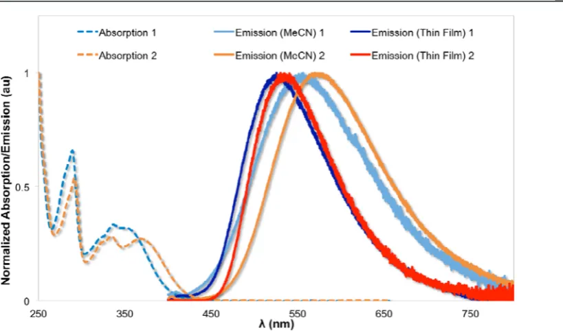
Both 1 and 2 exhibit irreversible oxidation and reversible oxidation waves in MeCN solution by cyclic voltammetry (Table S1 and Figure S20). The HOMO of 1 (−5.93 eV) is slightly lower than that of 2 (−5.87 eV) because of the presence of the electron-withdrawing fluorine atom. The LUMO of 1 (−2.92 eV) is slightly higher than that of 2 (−2.99 eV), which is due to the increased level of conjugation imparted by the second carbazole moiety that lowers the LUMO in 2. These structure−property relationships are mirrored in the absorption spectra wherein the absorption profile of 2 is slightly red-shifted compared with that of 1 (Figure 1).
Solution photoluminescence of the two materials was investigated in MeCN. The primary photophysical parameters in solution are detailed inTable 1(absorption data reported in Table S2).
The emission in MeCN solution and infilm for both1and2 (Figure 1) is broad and unstructured, which is characteristic of CT emission. The excitation and absorption spectra match, corroborating the high level of purity determined by the compound characterization. The solution-state emission for1 and 2 is red-shifted by ∼30 and ∼40 nm, respectively,
compared to emission in film (vide inf ra). In solution, the emission for both1 and2is weak and the observed emission lifetimes are in the nanosecond regime. There is little change in the photophysical properties upon removal of O2, suggesting that in MeCN1 and 2 act asfluorophores with no observed TADF. This result, coupled with the observation that PL is red-shifted in solution compared to thinfilm, indicates that solvent interactions may lower the energy of the triplet (T1) with respect to the singlet (S1), resulting in an increasedΔEST, and thus, TADF would be switched off. By point of comparison, dicarbazolyldicyanobenzene (2CzPN), which does not contain the tethered imidazolium units, was shown by Adachi to emit at 473 nm in a toluene solution via TADF with a photo-luminescence quantum yield,ΦPL, of 47%.
11
Photoluminescence in thin films is the process of interest when considering these materials as TADF emitters. In a spin-coated neatfilm,1and2 show significantly stronger emission than in solution, with ΦPL values of 0.093 and 0.207, respectively, under aerated conditions. As interactions between chromophores often lead to quenching of PL, we also investigated the emission when the materials were diluted in a PMMA host. In samples with 10 wt %1and2in PMMA,ΦPL improved substantially withΦPLvalues of 0.447 and 0.730 for1 and2, respectively.Table 2provides full details of the measured photophysical properties of thefilms.
The long (microsecond) average lifetime and the shortening of the lifetime in air suggest a triplet-derived TADF process is occurring, in contrast to the solution data. The PL decay is observed to be complex, spanning 4 orders of magnitude of time and requiring 7−9 exponential functions to adequately describe it. These exponentials are, however, simply para-metrization as the decay is derived from a mixture of initial
fluorescence from the singlet (often denoted as prompt
[image:3.625.125.535.58.299.2]fluorescence), and delayed fluorescence mediated by inter-system crossing (ISC) followed by slow reverse interinter-system crossing (RISC) populated emission from the singlet, subject to Boltzmann statistics. Consequently, to permit a fair comparison of the two materials, and between aerated and vacuum Figure 1.Normalized absorption spectra of1and2in aerated MeCN at 298 K and normalized emission spectra in deaerated MeCN at 298 K and in pristine thinfilm under air.
Table 1. Photoluminescence of 1 and 2 in MeCN at 298 K
λem(nm)a,b λem(nm)a,c ΦPLb,d ΦPLc,d τe(ns)b,e τe(ns)c,e
1 556 558 0.014 0.029 2.90 3.26
2 574 572 0.021 0.026 4.44 4.97
aλ
excat 360 nm.bMeasured in aerated solvent.cMeasured in degassed
solvent.dQuinine sulfate used as the reference (ΦPL= 0.546 in 1 N
conditions, an average lifetime can be calculated that is the weighted average of the individual components with their pre-exponential factors. Full details of all the decay components along with an experimental description are provided inTable S3 and Figures S21 and S22. We observe that in 10 wt %1in PMMA theΦPLincreases from 0.447 to 0.557 when going from air to degassed conditions, while the emission lifetime increases from 2.54 to 6.14μs. In 10 wt % 2in PMMA, ΦPLincreases from 0.730 to 0.900 while the emission lifetime increases from 1.08 to 6.34 μs. The increase in lifetimes and PLQY upon removal of oxygen allows us to assign emission infilms of1and 2to TADF. The absence of complete quenching of long-lived emission in thefilms is likely due to the fact that both in neat
films and when doped in PMMA, some of the chromophores will be partially encapsulated, hampering the ability of oxygen to diffuse into thefilm.
■
ELECTROLUMINESCENT DEVICES: LEECSLEECs were prepared on top of a patterned indium tin oxide (ITO)-coated glass substrate. Prior to the deposition of the emitting layer, 80 nm of PEDOT:PSS was coated to increase the reproducibility of the cells. The emitting layer (100 nm) was prepared by spin-coating of an MeCN solution consisting of the emitting compound alone or with the addition of an ionic liquid (IL), 1-butyl-3-methylimidazolium hexafl uorophos-phate ([Bmim][PF6]), at a molar ratio of 4:1 that is typically used in iTMC LEECs. To complete the devices, a layer of 70 nm of aluminum that serves as the top electrode was thermally evaporated onto the devices in a high-vacuum chamber integrated into the inert atmosphere glovebox.
To determine the performance of the LEECs, the devices were operated using a block-wave pulsed current driving method (1000 Hz and 50% of duty cycle) at different average current densities of 10, 25, and 50 A m−2. This operational mode was selected over constant voltage mode as it decreases the turn-on time and leads to a more sustained behavior versus time.32,33 Using this method but also using constant-voltage driving, we were unable to observe light emission from the device employing1 as the emitting component in single-layer devices. The driving voltage did decrease upon application of the pulsed current, indicating that electronic charges were able to inject and move through thefilm. However, the reason that no light emission was observed remains unclear at this moment. When 2 was employed as the emitting layer, the situation changed drastically as with these devices we did observe light emission. The luminance and average voltage are depicted in Figure 2for LEECs using2 (L1) and 2:IL (L2) (4:1) as the component(s) for the light-emitting layer. Thefigures of merit
for the different devices studied are summarized in Table 3. Initially, for both LEECs, the average voltage applied drops
[image:4.625.344.546.54.374.2]rapidly over thefirst several seconds [as also observed for the device employing 1 (not shown)]. Coinciding with the decrease in driving voltage, an increase in luminance was observed. This reached a maximal value and then slowly decreased over time. This is typical for LEECs, as the injection barrier for electrons and holes is reduced because of the migration of ions to the electrode interfaces and the subsequent formation of doped regions.34−36The reduction of the injection barrier leads to the reduced driving voltage to sustain the set current density. With an increasing operating time, the doped regions expand, leading to a slowly increasing quenching of the Table 2. Photoluminescence of 1 and 2 in Neat and Doped
Thin Films
film (neat) fi
lm (10% doped in PMMA) λem
(nm) ΦPLa
τave
(μs) (nm)λem ΦPLa
τave
(μs)
1 aerated 530 0.09 0.26 490 0.44 2.54 degassed 0.10 0.96 0.56 6.14
2 aerated 536 0.21 0.97 500 0.73 1.08 degassed 0.21 2.73 0.90 6.34
aPLQY measured using a Hamamatsu Absolute PL quantum yield
measurement system, with an integrating sphere and nitrogen purge where appropriate.
Figure 2.Luminance and average voltage (inset) for LEECs using2as the emissive material measured at different average current densities [50 A m−2 (red squares), 25 A m−2 (green circles), and 10 A m−2
[image:4.625.325.565.493.585.2](orange triangles)]. Top device L1: ITO/PEDOT:PSS/2/Al. Bottom device L2: ITO/PEDOT:PSS/2:[Bmim][PF6] 4:1/Al.
Table 3. Performance of LEEC Devices
electroluminescence
LEEC
devicea average current density(A m−2) (cd mLummax−2)a (lm WPCEmax−1) EQE(%)max
L1 10 13 0.7 0.39
25 24 0.4 0.29
50 26 0.2 0.16
L2 25 10 0.2 0.12
50 17 0.1 0.10
aDevice L1: ITO/PEDOT:PSS/2/Al. Device L2: ITO/PEDOT:PSS/ 2:[Bmim][PF6] 4:1/Al biased with a block wave-pulsed current at a
frequency of 1000 Hz and a duty cycle of 50% at different current densities.
excitons and, as a result, a (nonpermanent) luminance reduction.37
We found that the LEECs containing additional ions in the emitting layer have a luminance (and efficiency) lower than that of the LEECs with only the emitting material2(Figure 2). This was initially surprising as generally an increased luminance is observed upon the addition of IL to the emitting layer in LEECs employing iTMCs.38,39 This increased luminance is accompanied by an increase inΦPLof the emitting layers due to an increase in the interemitter distance, which leads to a reduction in the level of concentration quenching. The results, here obtained, indicate that concentration quenching effects are less important in the TADF materials then they are in iTMC-based LEECs. The addition of the IL, similar to what was observed in MeCN solution, generates a more polar environ-ment, widening the singlet−triplet energy gap and arresting the TADF mechanism in the device.
In Figure 2, it is also clearly seen that the luminance decreases with decreasing current density, but this relationship is far from linear. A similar behavior has been observed for iTMC-based LEECs.40−42 This effect was attributed to a reduced level of quenching of the excitons due to either a reduction of charge carriers, excited states, or both. As the devices are operated at a fixed average current density, the efficiency of the devices is directly proportional to the luminance. With a 5-fold decrease in current density, the luminance of the2 only (no IL, device L1) device drops only from approximately 26 to 13 cd m−2. Hence, the device power efficiency strongly increases to 0.7 lm W−1 with an external quantum efficiency (EQE) of 0.39% (assuming Lambertian emission).
The electroluminescence (EL) spectra are shown inFigure S21. All cells emit homogeneously from the active area. The spectra are rather similar to those obtained by photoexcitation, featuring an unstructured green emission centered at 538 nm (CIE coordinates of 0.35, 0.57).
■
ELECTROLUMINESCENT DEVICES: OLEDS [image:5.625.338.559.52.272.2]We also explored1and2as the emitter layer (EML,∼20 nm) in solution-processed multilayer architecture OLEDs shown in Figure 3, in which PEDOT:PSS (∼30 nm) acts as the hole
injection layer (HIL) and PVK (∼30 nm) behaves as the hole-transporting layer (HTL) and electron/exciton blocking layer (EBL) because of its high lowest unoccupied molecular orbital (LUMO) level (2.2 eV) and triplet level (2.5−2.9 eV).43,44The PVK was coated with the emissive layer and B3PYMPM deposited as the electron-transporting layer (ETL) because of its high electron mobility and excellent hole blocking ability45 associated with its deep highest occupied molecular orbital (HOMO) level (6.8 eV). Calcium coated with aluminum was used as the cathode. For devices 1 and 2, the emissive layer (EML) consisted of1 and2 doped into mCP (T1= 2.9 eV) and OXD-7 (T1= 2.7 eV), respectively, which are cohosts for the emitters.46 Generally, the multilayer structure can either Figure 3. Schematic diagram of the device structure: The emissive
[image:5.625.328.558.304.581.2]layer is either pristine1/2or doped as mCP:OXD-7:1/2(70:20:10). Abbreviations: PEDOT:PSS, poly(3,4-ethylenedioxythiophene):poly-(styrenesulfonate); PVK, poly(N-vinylcarbazole); B3PYMPM, bis[4,6-(3,5-di-3-pyridylphenyl)-2-methylpyrimidine]; mCP, 3,5′-N,N′ -dicar-bazole-benzene; OXD-7, 1,3-bis[(4-tert -butylphenyl)-1,3,4-oxadiazolyl]phenylene.
[image:5.625.57.303.537.679.2]Figure 4. (a) Current density and (b) luminance vs voltage characteristics of the devices.
balance hole/electron in the EML or confine the excitons inside the EML to enhance the radiative recombination rate. As we found that neat 2 produced a viable LEEC, we also made devices with neatfilms of the emitters (1 or 2, 10 nm thick, device3 or4, respectively).
Figure 4a displays the current density−voltage characteristic curves of the four devices based on emitters1and2. With the similar architectures, the devices exhibited similar current densities in the region of [−3 V, 3 V] where no emission was
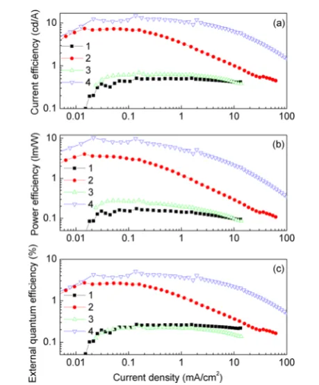
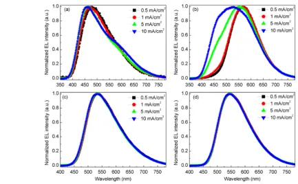
[image:6.625.69.272.182.320.2]observed. For the doped EML, device 2 showed a higher current density above 5 V and also a higher luminance. Device 2 also showed a current efficiency (CE), a power efficiency (PE), and an external quantum efficiency (EQE) much higher than those of device 1 with emitter 1 (see Figure 5). From Figure 6, we observe that the peak wavelength of device2was red-shifted by 99 nm compared to that of device1. Thus, the Commission Internationale de L’Eclairage (CIE) coordinates were changed from (0.42, 0.49) to (0.25, 0.31). Surprisingly, but analogous to what was observed with the LEECs, both the nondoped devices3and4exhibited better performance (Table 4) compared to that of doped devices1and2, respectively. For the devices with emitter2, lower driving voltages were realized, especially for device4, which required only 3.6 V to turn on. It is worth mentioning that the maximal CE, PE, and EQE were approximately double those of device2. In contrast, devices1 and3 achieved similar luminous efficiencies, even though the EL spectra are significantly different (shown in Figures 6and 7a,c). Unlike the other devices, device 2 showed current density-dependent EL spectra as the component from the cohost increased with the current density mainly due to incomplete host−guest energy transfer efficiency and exciplex emission.47 Devices 2 and 4 showed not only better charge injection/transport but also higher luminance. Given that emitters 1 and 2 have rather similar HOMO and LUMO Table 4. Comparison of the Performance of the Four OLEDs
OLED devicea(emitter) V
onb(V) λpeakc(nm) fwhmd(nm) EQEmaxe(%) CEmax.f(cd/A) PEmaxg(lm/W) CIEh
1(doped−1) 9.5 467 148 0.3 0.5 0.2 (0.25, 0.31)
2(doped−2) 5.8 566 137 2.7 7.4 4.0 (0.42, 0.49)
3(neat−1) 7.5 532 132 0.3 0.7 0.3 (0.38, 0.52)
4(neat−2) 3.6 546 128 5.1 14.9 10.3 (0.41, 0.53)
aFor device architecture, seeFigure 3and the text.bTurn-on voltage at 1 cd/m2.cPeak wavelength at 1 mA/cm2.dFull width at half-maximum of the
EL spectrum at 1 mA/cm2.eMaximal external quantum efficiency.fMaximal current efficiency.gMaximal current efficiency.hThe Commission Internationale de L’Eclairage coordinates at 1 mA/cm2.
[image:6.625.65.499.472.740.2]Figure 6.Comparison of the normalized EL spectra at 1 mA/cm2of the devices.
energy levels, which are likely not the origin of the difference in charge injection/transport, it is proposed that theC2symmetry of emitter2may induce better packing in the solid state, giving better charge transport. The higher luminance is attributed to the enhancedfilm photoluminescence quantum yield observed in emitter2. From the maximal EQE of 5.1% of device4, we can estimate that the delayed fluorescent component of the quantum yield of 2 is ∼18.4% according to eq 2,48which is consistent with the value of 21.4% (Table 2) calculated from the transient measurement.
γη η
η
= + Φ
− − Φ
⎡ ⎣ ⎢ ⎢ ⎤ ⎦ ⎥ ⎥ EQE 1 4 3
4 1 ( )
oc PL
DF
PL DF (2)
where γis the ratio of hole−electron recombination rate and considered to be 1 here, ηoc is the outcoupling efficiency (∼20%), ηPL is the quantum yield, and ΦDF is the delayed component of the quantum yield.
■
CONCLUSIONSIn summary, we synthesized in good yield and characterized the
first charged organic TADF emitters. Using 2, green light-emitting devices that operate as LEECs and OLEDs were prepared. For the LEECs, the operating voltages are very low with an average of 2.7 V. The efficiency increases strongly with a decreasing carrier density and reaches a maximal external quantum efficiency of∼0.4%.
We demonstrated that the solution-processed and color-stable OLEDs with pristinefilms outperformed the devices with the doped EML, which is rarely realized in the structure with TADF characteristics (EQE up to 5.1%). Device4exhibited the highest EQE of any single-component TADF OLED to date. Further optimization of the molecular structure for high quantum yield will pave the way for orthogonally spin-coated OLEDs with high luminous efficiency, which would lead to all solution-processed devices and practical application.
■
ASSOCIATED CONTENT*
S Supporting InformationThe Supporting Information is available free of charge on the ACS Publications website at DOI: 10.1021/acs.chemma-ter.5b03245.
Experimental section, nuclear magnetic resonance spectra for all compounds, supplementary electro-chemical data for 1 and 2, supplementary absorption data for 1 and 2, supplementary time-resolved luminescence data for 1 and 2, and supplementary power intensity as a function of excitation power data for 1and2(PDF)
■
AUTHOR INFORMATIONCorresponding Author
*Fax: +44-1334 463808. Telephone: +44-1334 463826. E-mail: [email protected].
Notes
The authors declare no competingfinancial interest.
■
ACKNOWLEDGMENTSE.Z.-C. thanks the University of St Andrews for support. We are grateful to the EPSRC for financial support (Grants EP/ J01771X and EP/J00916). I.D.W.S. is a Royal Society Wolfson Research Merit Award Holder. We thank the EPSRC UK
National Mass Spectrometry Facility at Swansea University for analytical services. This work has been supported by the Spanish Ministry of Economy and Competitiveness (MAT2014-55200 and FAFOR), and by the Generalitat Valenciana (Prometeo/2012/053).
■
REFERENCES(1) AlSalhi, M. S.; Alam, J.; Dass, L. A.; Raja, M. Recent advances in conjugated polymers for light emitting devices.Int. J. Mol. Sci.2011,
12, 2036.
(2) Sasabe, H.; Kido, J. Development of high performance OLEDs for general lighting.J. Mater. Chem. C2013,1, 1699.
(3) Adachi, C. Third-generation organic electroluminescence materials.Jpn. J. Appl. Phys.2014,53, 060101.
(4) Yersin, H.; Rausch, A. F.; Czerwieniec, R.; Hofbeck, T.; Fischer, T. The triplet state of organo-transition metal compounds. Triplet harvesting and singlet harvesting for efficient OLEDs. Coord. Chem. Rev.2011,255, 2622.
(5) Sasabe, H.; Kido, J. Recent Progress in Phosphorescent Organic Light-Emitting Devices.Eur. J. Org. Chem.2013,2013, 7653.
(6) Baldo, M. A.; O’Brien, D. F.; You, Y.; Shoustikov, A.; Sibley, S.; Thompson, M. E.; Forrest, S. R. Highly efficient phosphorescent emission from organic electroluminescent devices.Nature1998,395, 151.
(7) Plummer, E. A.; van Dijken, A.; Hofstraat, J. W.; De Cola, L.; Brunner, K. Electrophosphorescent Devices Based on Cationic Complexes: Control of Switch-on Voltage and Efficiency Through Modification of Charge Injection and Charge Transport.Adv. Funct. Mater.2005,15, 281.
(8) Adachi, C.; Baldo, M. A.; Thompson, M. E.; Forrest, S. R. Nearly 100% internal phosphorescence efficiency in an organic light emitting device.J. Appl. Phys.2001,90, 5048.
(9) Lamansky, S.; Djurovich, P.; Murphy, D.; Abdel-Razzaq, F.; Lee, H.-E.; Adachi, C.; Burrows, P. E.; Forrest, S. R.; Thompson, M. E. Highly Phosphorescent Bis-Cyclometalated Iridium Complexes: Synthesis, Photophysical Characterization, and Use in Organic Light Emitting Diodes.J. Am. Chem. Soc.2001,123, 4304.
(10) Parker, C. A.; Hatchard, C. G. Triplet-singlet emission in fluid solutions. Phosphorescence of eosin.Trans. Faraday Soc. 1961,57, 1894.
(11) Uoyama, H.; Goushi, K.; Shizu, K.; Nomura, H.; Adachi, C. Highly efficient organic light-emitting diodes from delayed fluo-rescence.Nature2012,492, 234.
(12) Nakanotani, H.; Higuchi, T.; Furukawa, T.; Masui, K.; Morimoto, K.; Numata, M.; Tanaka, H.; Sagara, Y.; Yasuda, T.; Adachi, C. High-efficiency organic light-emitting diodes with fluorescent emitters.Nat. Commun.2014,5, 4016.
(13) Zhang, Q.; Li, J.; Shizu, K.; Huang, S.; Hirata, S.; Miyazaki, H.; Adachi, C. Design of efficient thermally activated delayed fluorescence materials for pure blue organic light emitting diodes.J. Am. Chem. Soc.
2012,134, 14706.
(14) Zhang, Q.; Li, B.; Huang, S.; Nomura, H.; Tanaka, H.; Adachi, C. Efficient blue organic light-emitting diodes employing thermally activated delayed fluorescence.Nat. Photonics2014,8, 326.
(15) Reineke, S. Organic light-emitting diodes: Phosphorescence meets its match.Nat. Photonics2014,8, 269.
(16) Endo, A.; Sato, K.; Yoshimura, K.; Kai, T.; Kawada, A.; Miyazaki, H.; Adachi, C. Efficient up-conversion of triplet excitons into a singlet state and its application for organic light emitting diodes.Appl. Phys. Lett.2011,98, 083302.
(17) Lee, S. Y.; Yasuda, T.; Yang, Y. S.; Zhang, Q.; Adachi, C. Luminous butterflies: efficient exciton harvesting by benzophenone derivatives for full-color delayed fluorescence OLEDs.Angew. Chem., Int. Ed.2014,53, 6402.
(19) Pei, Q. B.; Yu, G.; Zhang, C.; Yang, Y.; Heeger, A. J. Polymer Light-Emitting Electrochemical-Cells.Science1995,269, 1086.
(20) Costa, R. D.; Ortí, E.; Bolink, H. J.; Monti, F.; Accorsi, G.; Armaroli, N. Luminescent Ionic Transition-Metal Complexes for Light-Emitting Electrochemical Cells.Angew. Chem., Int. Ed.2012,51, 8178.
(21) Hu, T.; He, L.; Duan, L.; Qiu, Y. Solid-state light-emitting electrochemical cells based on ionic iridium(iii) complexes.J. Mater. Chem.2012,22, 4206.
(22) Meier, S. B.; Tordera, D.; Pertegas, A.; Roldá n-Carmona, C.;́ Ortí, E.; Bolink, H. J. Light-emitting electrochemical cells: recent progress and future prospects.Mater. Today2014,17, 217.
(23) Ladouceur, S.; Zysman-Colman, E. A Comprehensive Survey of Cationic Iridium(III) Complexes Bearing Nontraditional Ligand Chelation Motifs.Eur. J. Inorg. Chem.2013,2013, 2985.
(24) Costa, R. D.; Ortí, E.; Bolink, H. J. Recent advances in light-emitting electrochemical cells.Pure Appl. Chem.2011,83, 2115−2128. (25) Pertegás, A.; Tordera, D.; Serrano-Pérez, J. J.; Ortí, E.; Bolink, H. J. Light-Emitting Electrochemical Cells Using Cyanine Dyes as the Active Components.J. Am. Chem. Soc.2013,135, 18008.
(26) Tang, S.; Tan, W.-Y.; Zhu, X.-H.; Edman, L. Small-molecule light-emitting electrochemical cells: evidence for in situ electro-chemical doping and functional operation.Chem. Commun.2013,49, 4926.
(27) Chen, P.; Wang, L. P.; Tan, W. Y.; Peng, Q. M.; Zhang, S. T.; Zhu, X. H.; Li, F. Delayed fluorescence in a solution-processable pure red molecular organic emitter based on dithienylbenzothiadiazole: a joint optical, electroluminescence, and magnetoelectroluminescence study.ACS Appl. Mater. Interfaces2015,7, 2972.
(28) Albrecht, K.; Matsuoka, K.; Fujita, K.; Yamamoto, K. Carbazole Dendrimers as Solution-Processable Thermally Activated Delayed-Fluorescence Materials.Angew. Chem., Int. Ed.2015,54, 5677.
(29) Zysman-Colman, E.; Arias, K.; Siegel, J. S. Synthesis of Arylbromides from Arenes and NBS in Acetonitrile: A Convenient method for Aromatic Bromination.Can. J. Chem.2009,87, 440.
(30) Fernandes, R. A.; Gholap, S. P.; Mulay, S. V. A facile chemoselective deprotection of aryl silyl ethers using sodium hydride/ DMF and in situ protection of phenol with various groups.RSC Adv.
2014,4, 16438.
(31) Melhuish, W. H. Quantum Efficiences Of Fluorescence Of Organic Substances: Effect Of Solvent And Concentration Of The Fluorescent Solute 1.J. Phys. Chem.1961,65, 229.
(32) Shavaleev, N. M.; Scopelliti, R.; Gratzel, M.; Nazeeruddin, M.̈ K.; Pertegás, A.; Roldán-Carmona, C.; Tordera, D.; Bolink, H. J. Pulsed-current versus constant-voltage light-emitting electrochemical cells with trifluoromethyl-substituted cationic iridium(iii) complexes.J. Mater. Chem. C2013,1, 2241.
(33) Tordera, D.; Meier, S.; Lenes, M.; Costa, R. D.; Ortí, E.; Sarfert, W.; Bolink, H. J. Simple, Fast, Bright, and Stable Light Sources.Adv. Mater.2012,24, 897.
(34) van Reenen, S.; Matyba, P.; Dzwilewski, A.; Janssen, R. A. J.; Edman, L.; Kemerink, M. A Unifying Model for the Operation of Light-Emitting Electrochemical Cells. J. Am. Chem. Soc. 2010, 132, 13776.
(35) Rodovsky, D. B.; Reid, O. G.; Pingree, L. S. C.; Ginger, D. S. Concerted Emission and Local Potentiometry of Light-Emitting Electrochemical Cells.ACS Nano2010,4, 2673.
(36) Lenes, M.; Garcia-Belmonte, G.; Tordera, D.; Pertegas, A.;́ Bisquert, J.; Bolink, H. J. Operating Modes of Sandwiched Light-Emitting Electrochemical Cells.Adv. Funct. Mater.2011,21, 1581.
(37) Meier, S. B.; Hartmann, D.; Tordera, D.; Bolink, H. J.; Winnacker, A.; Sarfert, W. Dynamic doping and degradation in sandwich-type light-emitting electrochemical cells.Phys. Chem. Chem. Phys.2012,14, 10886.
(38) Costa, R. D.; Ortì, E.; Bolink, H. J.; Graber, S.; Schaffner, S.; Neuburger, M.; Housecroft, C. E.; Constable, E. C. Archetype Cationic Iridium Complexes and Their Use in Solid-State Light-Emitting Electrochemical Cells.Adv. Funct. Mater.2009,19, 3456.
(39) Parker, S. T.; Slinker, J. D.; Lowry, M. S.; Cox, M. P.; Bernhard, S.; Malliaras, G. G. Improved Turn-on Times of Iridium Electro-luminescent Devices by Use of Ionic Liquids.Chem. Mater.2005,17, 3187.
(40) Tordera, D.; Frey, J.; Vonlanthen, D.; Constable, E.; Pertegas,́ A.; Ortí, E.; Bolink, H. J.; Baranoff, E.; Nazeeruddin, M. K. Low Current Density Driving Leads to Efficient, Bright and Stable Green Electroluminescence.Adv. Energy Mater.2013,3, 1338.
(41) Tang, S.; Mindemark, J.; Araujo, C. M. G.; Brandell, D.; Edman, L. Identifying Key Properties of Electrolytes for Light-Emitting Electrochemical Cells.Chem. Mater.2014,26, 5083.
(42) Su, H.-C.; Hsu, J.-H. Improving the carrier balance of light-emitting electrochemical cells based on ionic transition metal complexes.Dalton Trans.2015,44, 8330.
(43) Jankus, V.; Monkman, A. P. Is Poly(vinylcarbazole) a Good Host for Blue Phosphorescent Dopants in PLEDs? Dimer Formation and Their Effects on the Triplet Energy Level of Poly(N-vinyl-carbazole) and Poly(N-Ethyl-2-VinylPoly(N-vinyl-carbazole). Adv. Funct. Mater.
2011,21, 3350.
(44) Burkhart, R. D.; Chakraborty, D. K. Binding energies of triplet excimers in poly(N-vinylcarbazole) solid films from laser-based kinetic spectroscopy between 15 and 55 K.J. Phys. Chem.1990,94, 4143.
(45) Sasabe, H.; Kido, J. Multifunctional Materials in High-Performance OLEDs: Challenges for Solid-State Lighting†. Chem. Mater.2011,23, 621.
(46) Chopra, N.; Lee, J.; Zheng, Y.; Eom, S.-H.; Xue, J.; So, F. High efficiency blue phosphorescent organic light-emitting device. Appl. Phys. Lett.2008,93, 143307.
(47) Chiu, T.-L.; Lee, P.-Y. Carrier Injection and Transport in Blue Phosphorescent Organic Light-Emitting Device with Oxadiazole Host.
Int. J. Mol. Sci.2012,13, 7575.
(48) Tao, Y.; Yuan, K.; Chen, T.; Xu, P.; Li, H.; Chen, R.; Zheng, C.; Zhang, L.; Huang, W. Thermally Activated Delayed Fluorescence Materials Towards the Breakthrough of Organoelectronics.Adv. Mater.