105 Available online at www.ijiere.com
International Journal of Innovative and Emerging
Research in Engineering
e-ISSN: 2394 - 3343 p-ISSN: 2394 - 5494
A Comparative Study of Conventional and Fast Converging
MPPT Techniques
Patel Sejal Kantibhai
a, Prof.Hitesh K Mehta
baP.G.Student, Department of Electrical Engineering, SCET collage, Surat, India
bAssistant Professor, Department of Electrical Engineering, SCET collage, Surat, India
ABSTRACT:
Traditionally, a maximum power point locus was used to provide a fast response which required extra control loop or intermittent disconnection of PV module. During the changes of solar irradiation, the conventional algorithms respond inaccurate and converging slow. This paper presents a simpler Fast converging MPPT technique that respond accurately when solar irradiation level is change. In this modified algorithm, the relationship between the load line and I-V curve is used with trigonometry rule to obtain fast response. MATLAB simulation is carried out with the modified fast converging algorithm and conventional algorithm using DC-DC boost converter under a fast-changing solar irradiation level. Results showed that modified algorithm perform accurately and faster during the variation of solar irradiation level
.
Keywords:Fast converging, Perturb and Observe (P&O), Incremental Conductance, Maximum Power Point Tracking (MPPT), Photovoltaic (PV) system, DC-DC Boost converter.
I. INTRODUCTION
Solar energy has been one of the most active research areas in the past decades, both for grid connected and standalone application. However electricity generated by Photovoltaic systems is an unstable energy source because it is dependent on solar irradiation level and surrounding temperature [1]. Therefore, maximum power point tracking (MPPT) controller is needed to improve the efficiency of the PV system by ensuring that the PV module continuously supplies maximum power despite change in weather conditions.
Many MPPT algorithm have been introduced to improve the efficiency of the PV system, including fractional open circuit voltage, fractional short circuit current, fuzzy logic, neural network, Perturb and observe (P&O) and Incremental Conductance. If a dc-dc converter is connected in between the PV module and the load, the switching duty cycle of dc-dc converter is regulated to ensure the PV system always operates at the maximum power point (MPP) [4]. Among those algorithms, P&O and incremental conductance are the most popular algorithms. Both the algorithms rely on measurement of the PV array’s voltage and current and iteratively adjust a control parameter, typically by constant incremental value [5]. This implies a trade off in choosing the incremental value by which the controlled parameter is adjusted; small value decrease the losses in steady state due to small perturbation around the MPP, while large value improve the dynamic behaviour in situation involving quickly changing irradiation. Due to slow response of fixed step size algorithm, variable step size algorithm are introduced with impose additional algorithm complexity and hardware. Alsothe convergence of the system is slower as step size becomes smaller when algorithm close to peak of the P-V curves and the convergence of the system is also slower.
A few modified algorithms have been introduced to improve the converging speed during the variation in solar irradiation level which requires extra control loop or intermittent disconnection of the PV module. Although these algorithms can provide fast response, the complexity of the system is greatly increased. Therefore, this paper introduces a Modified MPPT algorithm which is able provide fast response without the requirement of an extra control loop [10].Fig.1 shows the block diagram of complete photovoltaic conversion system.
106
II. PV MODULE CHARACTERISTICS
A solar cell is basically a p-n semiconductor junction. When this cell is exposed to a light, a dc current is generated which varies linearly with the solar irradiance. The standard equivalent circuit of PV cell is shown in Fig.2.
Figure 2.Equivalent Circuit of Solar Cell [2]
The basic equation of PV module which describes the I-V characteristic is given in the following equation-(1):
I = IPH− Is[exp (q(v + IRs)
k TcA ) − 1] −
v + IRs
Rsh (1) Where IPH is the light generated current (A), Is is the cell saturation of dark current, q (= 1.6 ×10⁻¹⁹C) is an electron charge, k (= 1.38×10⁻²³J/K) is a Boltzmann’s constant, Tc is the cell’s working temperature, A is an ideal factor, Rsh and Rs are shunt and series resistance of PV module respectively
.
PV system is naturally exhibits a non linear I-V and P-V characteristics which vary with the radiant intensity and cell temperature. Based on the equation and using the electrical specification of SOLAREX MSX60 [2] which is given in Table 1, the PV system characteristics have been is simulated using MATLAB/Simulink as shown in Fig.3
Table 1.Electrical characteristics of SOLAREX MSX60 PV module at 25 ◦C and 1000 W/m2[3]
Figure 3.(a) I-V and (b) P-V characteristics at different Insolation
Temperature and irradiation greatly affect the characteristics of PV module. The effect of various irradiation on the I-V and P-V characteristics is shown in Fig.3. It depicts that the current has got higher irradiance dependence which also results in the change of MPP.
Sr.No Parameter Value
1. Rated Power (Pmax) 59.9 W
2. Voltage at maximum Power (Vmp) 17.1 V
3. Current at maximum Power (Imp) 3.5 A
4. Open circuit Voltage (Voc) 21.0 V
5. Short circuit Current (Isc) 3.74 A
6. Total No. of Cell in Series (Ns) 36
7. Total No. of Parallel path (Np) 1
8. Ideality factor 1.2
9. Temperature Co-efficient at I sc (0.065±0.015)%/◦C
10. Temperature Co-efficient at Voc -(80±10)mV/◦C
107
III. CONVENTIONAL MPPTTECHNIQUE
Due to the non linear behavior of the PV module, there exists an optimum operating point in which PV module produce maximum power, named Maximum Power Point (MPP) which is significantly changes depending on the irradiance conditions. Therefore to track the MPP on-line, a special method called Maximum Power Point Tracking (MPPT) is employed.
A. Perturb and Observe (P&O)
The P&O is widely adopted due to its simple implementation. This algorithm operates by periodically perturbing the control variable and comparing the instantaneous PV powers after and before the perturbation. Fig. 4(a) presents the flow chart of the P&O algorithm, where the sign of the next perturbation (k) depend on the sign of the PV power change.
If the PV power at the instant k increases with respect to the PV power at the instant k-1 the voltage perturbation ∆V conserves the sign of the previous perturbation; in contrast, if the PV power decreases at the instant k the voltage perturbation sign is changed. The drawback of this algorithm is: At steady state operating point is oscillate around the MPP, which gives rises in power loss.
B. Incremental Conductance Method
Unlike P&O, slope of the P-V curve is used by the incremental conductance algorithm to vary the duty cycle of converter [8]. This is based on the fact that the slope of the P-V curve is zero at the MPP, Positive on the left of the MPP, and negative on the right, as given by
𝐝𝐏 𝐝𝐕
⁄ = 𝟎 At MPP; 𝐝𝐏 𝐝𝐕⁄ > 0 𝐿𝑒𝑓𝑡 𝑜𝑓 𝑀𝑃𝑃; 𝐝𝐏
𝐝𝐕 < 0 𝑅𝑖𝑔ℎ𝑡 𝑜𝑓 𝑀𝑃𝑃
Since, 𝑑𝑃
𝑑𝑉= 𝐼 + 𝑉
𝑑𝐼
𝑑𝑉= 0
The MPP can thus be tracked by comparing the instantaneous conductance (I/V) to the incremental conductance (dI/dV) as shown in the flowchart in Fig. 4(b). Once the MPP reached, the operation of PV module is maintained at that point unless a change in dI is noted which indicating a change in atmospheric conditions and MPP.
If Conventional Incremental Conductance algorithm finds that the operating point is at peak of PV curve, then the duty cycle of converter is fixed and no oscillation during this stage occurs until changed in the slop rises. In actual operation, Zero slope condition is rarely achieved due to truncation error of numerical differentiation. Apart from steady state oscillation, the conventional Incremental Conductance algorithm is unable to respond accurately at the first step change in duty cycle of the converter after the increase in solar irradiation level. Also the changes in voltage and current during the change in solar irradiation and load resistance are not well considered.Table.2 shows the summary of change in voltage and current against the changes in solar irradiation and load resistance.
Figure 4.Flowchart for (a) Perturb and Observe (P&O)[6](b) Incremental Conductance[7] (b)
108
Table 2
.
Variation in Voltage and Current of PV module During the Variation in Solar Irradiation and Load Resistance [9]Variation of Voltage (dV) Variation of Current (dI)
Solar irradiation Increase Positive Positive
Decrease Negative Negative
Load Resistance Increase Positive Negative
Decrease Negative Positive
IV. MODIFIED FAST CONVERGING MPPTTECHNIQUE
The Modified algorithm adopts the relationship between the load line and the I-V curve. In this Modified algorithm, only the voltage and current of PV module are sensed by the MPPT controller [10].
The relationships of the voltage and current of Boost converter between the input and output sides are given by equations (2) and (3).
V in= (1-d)* V out…………. (2) I in =
1
(1−d)∗ Iout…..…… (3)
Where V in is the input voltage of the converter (voltage of the PV module VPV) and I in is the input current of the converter
(current of the PV module IPV).
Under any operating conditions, the load resistance can be calculated by substituting the duty cycle, voltage, and current of PV module given by,
Rload= 1 (1−d)2∗
VPV
IPV (4)
The new duty cycle corresponding variation in irradiation is given by,
𝐷 =√𝑎−1
√𝑎 ; Where, a= VPV
IPV ∗ 𝑅𝑙𝑜𝑎𝑑 (5)
For the case of load variations, Eq. (4) is used to calculate the new resistance, then VPV and IPV are substituted into Eq.
(5) to obtain the new duty cycle
.
For Solar irradiation variation:
When solar irradiation level is decrease to 0.4 kW/m2 from 1.0kW/m2 (Fig.5(a)), while duty cycle of converter remains
unchanged, the operating point of PV module is at point A(V1,I1) of load line1 which is far away from the MPP of
0.4kW/m2, point C in Fig.5(a). In order to perturb the operating point of PV module, approximated value are substituted
into Eq.(5) to ensure the PV module operates near to new MPP. The current of point A, I1 is close to short circuit current
and current of MPP is always approximated by 0.8*I sc & voltage of MPP for each level of solar irradiation are closed to
each another. Hence, the previous MPP voltage Vmpp and I1 are substituted into Eq.(5) to reach the new MPP point
B(V2,I2).With single perturbation, operating point of the PV module rapidly converges to new MPP point (from point A to
point B). Finally, a conventional incremental conductance is used to track the new MPP point C. Therefore, the converging time from point A to point C is greatly reduced.
109 Similar algorithm is used when solar irradiation level changes from low to high as shown in Fig.5(b). Here initially the PV module operates at load line 2, at 0.4kW/m2 insolation. Then, if solar irradiation increase to 1.0kW/m2, with the duty cycle
of converter remain unchaged, the operating point is at D(V1,I1) of load line 2which is far away from the MPP of 1.0kW/m2.
The previous MPP voltage, Vmpp is approximated as the voltage of new MPP, however the operating current I1 is far away
from the short circuit current of 1.0kW/m2. Thus, an additional step is required to ensure the operating current of PV module
is near to the Isc of new MPP. As shown in Fig.5(b), applying trigonometry rule to point E, Voc1.0 and Vmpp0.4 which form a
right angle rectangle, the operating current Ix, which is near to the Isc of 1.0kW/m2,
Ix=
Voc−Vmpp
Voc−V1 ∗ I1 (6)
By substituting value of Ix and voltage of MPP in Eq. (5), new duty cycle is obtained. In this Vmpp is the voltage of the MPP
before the variation in solar irradiation. The Voc of PV module is the approximated open circuit voltage obtained from
Vmpp/0.8. V1&I1 are the voltage and current of PV module after the variation in solar irradiation. With the new duty cycle,
PV module is operates close to new MPP. Then, the conventional incremental conductance algorithm is used to track the MPP.
C. Flow chart of Modified MPPT Technique
Fig.6 shows the flow chart for Fast converging MPPT algorithm.
Figure 6 Flow chart of Fast Converging MPPT Method [10]
Initially, a flag value is set to zero. This flag value used to indicate that the MPP is reached when it is set to 1. If flag value is zero, the conventional Incremental Conductance algorithm is implemented with the use of equation,
|𝑑𝐼
𝑑𝑉+
𝐼
𝑉| < 0.06 (7)
A permitted error of 0.06 is applied to eliminate the steady state oscillation. When condition in Eq. (7) is reached, the system operates at MPP, which sets flag to 1. Then it goes into the improved algorithm, in which program continues checking the conditions of Eq. (7).
110
V. MATLAB MODELLING AND SIMULATION
D. Simulink Model
Simulink model of PV system with Boost converter and MPPT tracker is shown in Fig.7, where PV module has mathematically modeled. The values of components in the converter are as follows: Cin=3200e-6 F, Cout=37e-6 F,
L=360e-6 H and load=40 Ohm and the switching frequency of converter is set to 10 kHZ. Here basic Conventional MPPT and Fast converging MPPT method is used as tracker
.
E. Results & Discussion
Conventional MPPT Method: Under the different insolation (1.0, 0.8, 0.6, 0.4 kW/m2) & at constant temperature (25◦C)
results of P&O and Incremental conductance method is carried out.
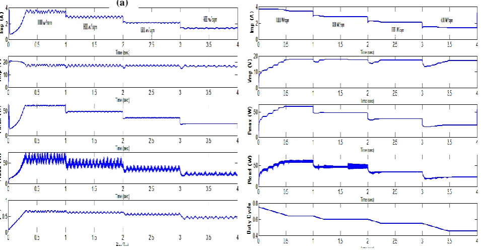
Figure 8 Simulation results of (a) P&O (b) Incremental Conductance at various Insolation level
From above results, it is seen that for P&O steady-state oscillation occurs after the MPP is reached because the perturbation continuously changes in both directions to maintain the MPP, which causes the power loss. For Conventional Incremental Conductance, steady state oscillations would be eliminated since the derivative of the power with respect to the voltage vanishes at MPP
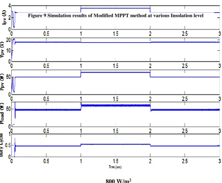
Fig.9 shows the simulation results for the modified MPPT algorithm. Initially the irradiation level is 0.8kW/m2.
Conventional Incremental Conductance method is used to track the MPP. The duty cycle of converter remain constant at 0.495 and power of the PV module is fixed at 48.59W. After the MPP tracked, flag value is set to 1, and no variation in the duty cycle until a variation in solar irradiation level is found at t= 1sec. At t=1.02 sec, the MPPT controller detected the
Figure 7 Simulation of PV system with Boost converter and MPPT tracker
(a)
111 increased in both voltage and current of PV module. Hence using Modified and conventional algorithm used to track the MPP for 1.0 kW/m2 in 0.2 sec with duty remain constant at 0.556 and power of module at 61.5 W.
Fig. 10 show the comparative analysis of conventional incremental conductance and Modified MPPT method is carried out and results are compared. The step size of duty cycle is 0.0002 and simulation time is 4sec, solar irradiation level varies from 1000 W/m2 to 800 W/m2.
From the simulation result for conventional Incremental Conductance, when insolation is decreased at t=2 sec, without noticing the changes in current and voltage, duty cycle first step change is confusing and obtains inaccurate responses. However the modified algorithm detects the decreased in solar irradiation and perform an accurate variation in the duty cycle. Therefore, the power is decreased from the first step until MPP reached. The response of the modified algorithm on the changes in solar irradiation is faster compared with that of conventional algorithm, which needs six steps and modified
800 W/m
21000 W/m
2
800 W/m
2Figure 9 Simulation results of Modified MPPT method at various Insolation level
112 algorithm shows almost zero oscillation in power which reduces the power loss.Table.3 shows the comparison between the modified MPPT method and conventional MPPT method.
Table 3 Comparison between the modified MPPT method and conventional MPPT method
MPPT Technique Perturb & Observe
Incremental Conductance
Modified MPPT Technique
PV array Dependent No No No
Steady state oscillation Yes Yes No
Analog or Digital? Both Digital Digital
Converges Speed Slow Slow Fast
Implementation Complexity
Low Medium Medium
Ability to track GMPP No No Yes
VI.CONCLUSION
The Modified algorithm responds to the variation in solar irradiation faster than the conventional algorithm as shown in the simulation results. Furthermore, there is almost zero steady state oscillation in modified MPPT algorithm and thus reduce the power losses. As a conclusion, a fast converging and low losses MPPT algorithm is introduced and simulated in the paper.
ACKNOWLEDGMENT
This research is the results of many endless hours of the hard work. It would not have been possible to complete without the help and supervision of many people. With a sense of gratitude and respect, I would like to extend my heartiest thanks to all those who provided help and guidance. I would like to articulate my profound gratitude and indebtedness to my guide Prof. Hitesh Mehta who has always been a source of constant motivation and guiding factor throughout the course of the project, in and out as well.
REFERENCES
[1] Vineet Singlal,Vijay Kumar Garg, “Modelling of Solar Photovoltaic Module&effect of insolation variation using Matlab/Simulink” International Journal of Advanced Engineering Technology ,July 2013.
[2] N.Pandiarajan,Rangananath Muthu, “Mathematical Modeling of Photovoltaic Module with Simulink,” International Conference on Electrical Energy Systems (ICEES), January 3-5,pp.314-319.2011.
[3] G. walker , “Evaluting MPPT converter topologies using MATLAB PV model, ”J.Electr.Electron.Eng.Aust.,vol.21,no.1,pp.49-56,2001.
[4] Mona Madorkar, Sarala Adhau, Manisha Sabley, and Praful Adhau ,“Design and Simulation of DC-DC Converters for Photovoltaic system on MATLAB,” International Conference on Industrial Instrument and Control, May 2015.
[5] T. Esram and P.L. Chapman, “Comparison of Photovoltaic array Maximum Power Point Tracking Techniques,” IEEE Transaction on Energy Conversion, vol.22, no.2, 2007, pp.439-449.
[6] Jacob James Nedumgatt, Jayakrishnan K. B., Umashankar S. , Vijaya kumar D., Kothari D P “Perturb and Observe MPPT Algorithm for Solar PV Systems-Modeling and Simulation,” India Conference (INDICON),Annual Conference of IEEE,pp.1-6,2011.
[7] Safari, A.; S. Mekhilef, "Simulation and Hardware Implementation of Incremental Conductance MPPT with Direct Control Method Using Cuk Converter," IEEE Transactions on Industrial Electronics, vol.58, no.4, pp.1154-1161, April 2011.
[8] Ioan Viorel BANU, Razvan Beniuga, Marcel Istrate, “ Comparative Analysis of the Perturb-and-Observed and Incremental Conductance MPPT Methods,” in Advanced Topics in Electrical engineering(ATEE), 2013 8th International Symposium on, pp.1-4, 23-25 May 2013.
[9] Tey Kok Soon, Saad Mekhilef, “Modified incremental conductance MPPT algorithm to mitigate inaccurate responses under fast-changing solar irradiation level,” Solar energy, vol.101, pp.333-342, Jan.2014.
![Figure 1.Complete Photovoltaic Conversion System [4]](https://thumb-us.123doks.com/thumbv2/123dok_us/8874887.1816261/1.595.170.402.650.758/figure-complete-photovoltaic-conversion-system.webp)
![Table 1.Electrical characteristics of SOLAREX MSX60 PV module at 25 ◦C and 1000 W/m2[3]](https://thumb-us.123doks.com/thumbv2/123dok_us/8874887.1816261/2.595.69.506.364.682/table-electrical-characteristics-solarex-msx-pv-module-c.webp)
 Incremental Conductance[7] (b)](https://thumb-us.123doks.com/thumbv2/123dok_us/8874887.1816261/3.595.63.511.184.443/figure-flowchart-perturb-observe-p-o-incremental-conductance.webp)
![Table 2.Variation in Voltage and Current of PV module During the Variation in Solar Irradiation and Load Resistance [9]](https://thumb-us.123doks.com/thumbv2/123dok_us/8874887.1816261/4.595.94.489.586.745/table-variation-voltage-current-module-variation-irradiation-resistance.webp)