Available Online at www.ijpret.com 162
INTERNATIONAL JOURNAL OF PURE AND
APPLIED RESEARCH IN ENGINEERING AND
TECHNOLOGY
A PATH FOR HORIZING YOUR INNOVATIVE WORK
AUTOMATION IN SHEET COUNTING AND FEEDING PROCESS FOR PACKAGING
INDUSTRY
ATUL GAWAI1, PRAFUL GAWAI2
1. ME Thermal, Mechanical Engineering Department, IBSS COE, Amravati, M.S
2. M. Tech Machine Design, Mechanical Engineering Department, Oriental Institute of Science and Technology, Bhopal, Madhya Pradesh, India
Accepted Date: 05/03/2015; Published Date: 01/05/2015
\
Abstract: In packaging industry, they are facing the difficulty of counting and feeding sheet manually on laminating machine. This is the task to make automatic feeding mechanism for sheet and counting. Automation, now a day’s automation is one of the important parts of any industry. It increases the production rate and minimizes time and also reduced human efforts. In this project the automation is about the feeding of sheet on the laminating machine. Then for automatic counting of sheet used diffused reflection type photoelectric switch GID 18-3A40 PC, manufactured by ideal company. Running condition a machine requires two operators. One for continuous feeding and one for checking the output product (laminated sheet). The operator count the sheet manually and then feed one by one on the conveyor belt. Automation is one of the mechanisms to reduced human effort and really increases production rate. Sheet once feed it automatically travel path on conveyor belt and counting of sheet also done by Infra-Red counter. For all this process we need only one operator to check the number of sheet displayed on screen and sheet at ones. This project is based on only mechanical linkage without used of any other mechanism like Hydraulic, Pneumatic etc.
Keywords: Automation, Feeding Process
Corresponding Author: MR. ATUL GAWAI
Access Online On:
www.ijpret.com
How to Cite This Article:
Available Online at www.ijpret.com 163
INTRODUCTION
Packaging is the science, art and technology of enclosing or protecting product for distribution, storage, sale, and use Packaging also refers to the process of design, evaluation, and production of packages. Package labeling (BrE) or labeling (AmE) is any written, electronic, or graphics communication on the packaging or on separated label. Packaging is heavily integrated into our daily lives, We see it all around us, on everyday items such as chocolate bars and potato chip (crisp) packets the main use for packaging is protection of the goods inside. Packaging may be looked at as several different types. For example a transport package or distribution package is the package from a used to ship, store, and handled the product or inner packages. Some identify a consumer package as one which is directed toward a consumer or household. It is sometimes convenient to categorize packages by layer or function: primary, secondary. The project presented here is based on world’s most powerful microcontroller based on Intel’s mcs-51 family, generally known as intel-80mcs-51. We have used its derivative Mtel-89c20mcs-51. In accordance to this IC some other Ics are also used. These include the 2X16 LCD display IC 4470, IC7805 used to give the regulated power supply and also there is opto-coupler used in the circuit to convert the voltage into digital signal and give it as input to the microcontroller. this project will help to get clear idea of how the object counter circuit actually works and what is the basic principle behind it. It will also make us understand how the objects passed from in between the transmitter and the receiver are counted and displayed on the LCD display. It will give a clear idea regarding the working, features and application of the different components used along with the complete circuit application.
BASIC THEORY:
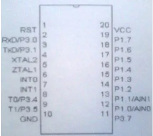
IR Sensor: Pin configuration
Available Online at www.ijpret.com 164
Pin Description:
VCC: Supply voltage, GND: Ground, Port 1: port 1 is an 8-bit bi-directional I/O Port. Port pins P1.2 to P1.7 provide internal pull-ups. The Port 1 output buffers can sink 20 mA and can drive LED display directly. Port 1 also receives code data during flash programming and verification, Port 3: Port 3 pins P3.0 to P3.5, P3.7 are seven bi-directional I/O pins with internal pull-ups p3.6 is hard wired as an input to the output of the on-chip comparator and is not accessible as a general purpose I/O pin. Port 3 alsoserves the function of various features of the AT89C2051, RST: reset input. All I/O pins are reset to 1 s as soon as RST goes high Holding the RST pin high for two Machine cycle while the oscillator is running resets the devices, XTL1: Input to the inverting oscillator amplifier and input to the internal clock operating circuit.
PROXIMETRY SWITCH:
Available Online at www.ijpret.com 165
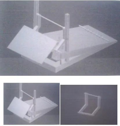
FEEDING MECHANISM:
Figure 2: Feeding Mechanism CAD-Model (With Roller, Roller Arm and Dead Weight)
Construction and Working: 1) The given fig shows the location of rollers and rollers operated by using separate driving power. 2) The roller are placed on the conveyor belt. 3) These rollers are adjustable as per thickness of sheet. 4) The set of sheet is placed on table. 5) That table having some inclination (10 deg) to give the motion to sheet in forward direction. 6) These sheet will then slide on the given contact surfaces. 7) These mechanism works on the principle of inertia and gravity force. 8) One vibrator is attached to able to table to maintain the accuracy to pass single sheet at a time.
Advantages: Installation is easy, low cost
Disadvantages: Vibrator need to be replaced always after few years.
IMPLEMENTATION METHODOLOGY:
Available Online at www.ijpret.com 166
Figure 3 : Proxy switch
Figure 4: Layout of proxy Switch and Counter Display.
GID: Infrared ray photoelectric switch
18 : Outward appearance code
3 : 10-30 V dc
A : Diffused reflection typed
P : PNP transistor output
C : Normally open + close
Working: The diffused typed sensor contains transmitter and receiver both in a singal unit. When the light rays emitted by transmitter are blocked by any object, then they get reflected and sense by receiver and pulse is generated at the output of proxy sensor. The puse generated is sense by the counter, it get increment by one and is displayed on six digit counter.
FEEDING MECHANISM AND DESIGN CALCULATION:
Available Online at www.ijpret.com 167
degrees in upward direction. The more accuracy is obtained by using upward direction. We had done the designed calculation about tray. The design roller placed on table as shown in fig. The bunch of sheet are placed between the rollers and tray surface in upward direction. The separate drive power is provided to roller. So we select the standard motor having rpm 1500 rpm. Whenever the roller start, the sheet which get contact inn roller in forward motion. As per designed calculation the pulling force for single sheet 0.7878N. when the single sheet will get motion the friction creates between the rollers and sheet. The whole roller assembly is mounted on the one mile steel rod. Having dia. 50mm. The required inertia ao singke sheet will be 2.45*103 kgm 2 the dead weight maintain continuous contact between rollers while sheet passing on conveyor belt. After passing single sheet the second sheet will get contact in roller. The process will completed upto last sheet.
DESIGN CALCULATION:
Design of Rollers
Figure 5: Roller
Normal size of sheet = (100*60) cm
Area of 1 sheet =0.6m2, No of sheet 1000
Step 1: Determination of weight,
Wt= total area *GSM* no of sheets
=0.6*350*1000
=210*103gm
=210Kg.
Available Online at www.ijpret.com 168
Step 2: Determination of an angle of friction
Figure 6: Angle of Friction
tanØ = (25/140) = 10.12=100(nearly)
Step 3: Coefficient of friction,
Figure 7: Coefficient of Friction
Tan Ø= F/N ; µN/N=µ; Tan12 =µ ;
µ=0.176
Step 4: Normal force and pulling force,
£FX=0 ; P-µN-WsinØ=0 ; £FY=0 ; N-WcosØ=0
N=WcosØ ; N=2.0601*cos10=2.0288N ;
P= (0.212*2.0288)+(2.0601*sin10)=0.7878N
For Maximum Condition:
TanØ=6/8=0.75 ; µ=tanØ ; µ=0.75 ; F=µ/N ;
Nmax= (0.7878/0.75)=1.05
Weight W= (1.05/9.81)=0.107.07gm
For Minimum Condition:
Available Online at www.ijpret.com 169
Nmini.= (0.7878/0.9)=0.87
Weight W= (0.87/9.81)=0.0886 Kg.
Wmax.=88.86 gm ; Taking Mean Weight
Wmean= (Wmax.+ Wmin.)/2= (107.07+88.86)/2
W= 100 gm/sheet, for 1000 sheet W=100Kg
Step 5: Determination of Inertia
W=100gm=0.1gm; m= 9.81N;
V=πdn/60=(π*100*103*1500)/60=7.85 m/s
I=mK2; K= 50mm; I=0.981*50*50=452.5Kg-mm2
Step 6: Determination of Torque
T=R*µmax=50*103*0.9 ; T= 0.045Nm;
P=2πNT/60=(2π*1500*0.045)/60 ; P=7.0685Watt.
Step 7: Synchronization
P=7.0685Watt; N=1000rpm; P=πdN/60
(7.065*103*103)=(π*d*1500)/60
d=0.09m; Pully Diameter d=90mm.
RESULT:
SENSORS READING FOR SHEET COUNT
SR NO NUMBER OF SHEET READING ON DISPLAY ERROR
1 500 550 +50
2 400 410 +10
3 200 201 +01
4 100 90 -10
5 100 100 ---
Available Online at www.ijpret.com 170
FOR FEEDING MECHANISM:
Successfully tested mechanism by making prototyped. Single sheet is passed at time according to machine need. Calculated friction and dead weight require.
CONCLUSION AND FUTURE SCOPE:
We have installed proximity switch on laminating machine along with connection box and sensor is working properly and display counter showing correct result. We completed the task and made prototype according to it. And also done the design calculation for final model
This mechanism can be used for any laminating machine for automatic feeding. Sensor can be use for any type of object counting.
REFRENCES:
1. V B Bhandari, Machine design, TATA McGraw HILL.
2. Khanchandani, P.S. Bimra, Power electronics.
3. B L Thareja, A K Theraja, Electrical Technology, S Chand Publication.
4. R S Khurmi, Machine Design, S Chand Publication.
5. http.Industrial %20automation%20ppt.htm.