Volume 2, Issue 10, October 2013
Page 324
Abstract
Leaf springs are one of the oldest suspension com ponents which are still frequently used, especially in automobile vehicles. These are used to absorb the fluctuating loads from the vehicle. Leaf spring is also known as laminated spring or carriage spring or flat spring. The main function of leaf spring is not only to support vertical load but also to isolate road induced vibrations. It is subjected to millions of load cycles leading to fatigue failure. In this connection an attempt is made to study the material optimization. Hence, existing steel, carbon fiber and boron fibers are evaluated and optimized the best one in concern with their performance. The boron fiber composite material can be replaceable with existing steel for master leaf spring. The master leaf spring is modeled in Pro/E (Wild Fire) 5.0 and analysis is carried out by using ANSYS 13.0 for better understanding. The objective of this project is to present modeling, stress analysis and material optimization of master leaf spring and comparison of deformation and stress results between steel leaf spring and composite leaf springs under same conditions.
Keywords: Leaf springs, Pro/E (Wild Fire) 5.0, ANSYS 13.0, Fatigue failure, Stress results:
1.
I
NTRODUCTIONThe suspension system is to isolate the vehicle body from road shocks and vibrations. It must also keep the tires in contact with the road, regardless of road surface. A basic suspension system consists of springs, axles, shock absorbers, arms, rods, and ball joints. The spring is the flexible component of the suspension. Basic types are leaf springs, coil springs, and torsion bars.
The suspension leaf spring is one of the potential items for weight reduction in automobile as it accounts for ten to twenty percent of the unsprung weight[3]. This helps in achieving the vehicle with improved riding qualities. It is well known that springs, are designed to absorb and store energy and then release it. Hence, the strain energy of the material becomes a major factor in designing the springs.
Leaf springs are known as flat springs or laminated springs. Their lengths are generally reduced from first plate to last plate and all the plates are held together to act as a single spring by means of central to band , containing two U clips bolted at the centre. The centre of the arc provides location for the axle , while tie holes are provided at either end for attaching to the heavy vehicle body[5]. Thus the laef spring acts as a linkage for holding the axle in position and thus separate linkage are not necessary. It makes the construction simple and strong
The development of a light flex suspension leaf spring is first achieved. Based on consideration of chipping resistance base part resistance and fatigue resistance, a carbon glass fiber hybrid laminated spring is constructed[6]. A general discussion on analysis and design of constant width, variable thickness, and composite leaf spring is presented. The fundamental characteristics of the double tapered FRP beam are evaluated for leaf spring application. Recent developments have been achieved in the field of materials improvement and quality assured for composite leaf springs based on microstructure mechanism[8].
All these literature report that the cost of composite; leaf spring is higher than that of steel leaf spring. Hence an attempt has been made to fabricate the composite leaf spring with the same cost as that of steel leaf spring.
Gulur Siddaramanna Shiva Shankar et al[1] In this paper a single leaf with variable thickness and width for constant cross sectional area of unidirectional glass fiber reinforced plastic (GFRP) with similar mechanical and geometrical properties to the multi leaf spring, was designed, fabricated (hand-lay up technique) and tested. The computer algorithm for design for variable with and variable thickness mono composite leaf spring is explained. Three-dimensional finite element analysis is used for verification of result obtained from experiment. In which the solid 45 element is used for steel leaf spring and solid layered 46 element is used for composite leaf spring .for the fabrication of mono composite leaf spring of E-glass /epoxy hand layup technique is used. The experimental test are carried on both steel and composite leaf spring and compared the result .It is observed that composite leaf spring is more superior than steel with a large weight reduction.
STRESS ANALYSIS AND MATERIAL
OPTIMIZATION OF MASTER LEAF SPRING
N.ANU RADHA1, C.SAILAJA2, S.PRASAD KUMAR3, U.CHANDRA SHEKAR REDDY4 & Dr. A.SIVA KUMAR5
1,2Assoc. Professor, 3Asst. Professor, 4M.Tech Student, 5Professor, Department of Mechanical
Volume 2, Issue 10, October 2013
Page 325
Mouleeswaaran Senthil Kumar et al[2] in this paper composite leaf spring is design on basis of fatigue failure . Theoretical equation for prediction fatigue life is formulated using fatigue modulus and its degrading rate. The dimensions and number of leaves for both steel leaf spring and composite leaf spring are considered to be same. The stress analysis is performed using finite element method .The element selected for analysis is solid 45 which behave like a spring. For the fabrication of each leave the filament winding machine is used and assembled this leaves together with the help of center bolt and four side clamps. The testing of steel multi leaf spring and composite multi leaf spring are carried out with the help of an electro hydraulic leaf spring test rig. Design and experimental fatigue analysis of composite multi leaf spring are carried out using data analysis. It is found that composite leaf spring has 67.35%lesser stress, 64.95% higher stiffness and 126.98% higher natural frequency and also 68.15% weight reduction is achieved.Mahmood M. Shokrieh et al.[3] in this paper a four-leaf steel spring used in the rear suspension system of light vehicles is analyzed using ANSYS V5.4 software. The finite element results showing stresses and deflections verified the existing analytical and experimental solutions. Using the results of the steel leaf spring, a composite one made from fiberglass with epoxy resin is designed and optimized using ANSYS. Main consideration is given to the optimization of the spring geometry. The objective was to obtain a spring with minimum weight that is capable of carrying given static external forces without failure. The design constraints were stresses (Tsai–Wu failure criterion) and displacements. The results showed that an optimum spring width decreases hyperbolically and the thickness increases linearly from the spring eyes towards the axle seat. Compared to the steel spring, the optimized composite spring has stresses that are much lower, the natural frequency is higher and the spring weight without eye units is nearly 80% lower.
J.P. Hou et al[4] this paper presents the design evolution process of a composite leaf spring for freight rail applications. Three designs of eye-end attachment for composite leaf springs are described. The material used is glass fibre reinforced polyester. Static testing and finite element analysis have been carried out to obtain the characteristics of the spring. Load– deflection curves and strain measurement as a function of load for the three designs tested have been plotted for comparison with FEA predicted values. The main concern associated with the first design is the delaminating failure at the interface of the fibres that have passed around the eye and the spring body, even though the design can withstand 150 KN static proof load and one million cycles fatigue load. FEA results confirmed that there is a high interlaminar shear stress concentration in that region. The second design feature is an additional transverse bandage around the region prone to delaminating. Delaminating was contained but not completely prevented. The third design overcomes the problem by ending the fibres at the end of the eye section.
S. Vijayarangan [5] showed the introduction of fiber reinforced plastics (FRP) made it possible to reduce the weight of a machine element without any reduction of the load carrying capacity. Because of FRP materials high elastic strain energy storage capacity and high strength-to-weight ratio compared with those of steel, multi-leaf steel springs are being replaced by mono- leaf FRP springs.
2.
S
PRINGM
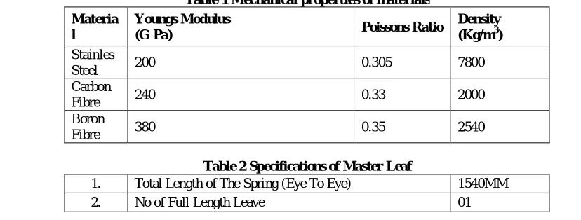
ATERIALSSteel alloys are the most commonly used spring materials. The most popular alloys include high-carbon (such as the music wire used for guitar strings), oil-tempered low-carbon, chrome silicon, chrome vanadium, and stainless steel. The selection of the spring material is usually the first step in parametric spring design. Material selection can be based on a number of factors, including temperature range, tensile strength, elastic modulus, fatigue life, corrosion resistance, electrical properties, cost, etc. The Helical Spring Design module requires the following material properties as input as Elastic Modulus (E), Poisson's Ratio (µ) and Material Mass Density (ρ).
Table 1 Mechanical properties of materials Materia
l
Youngs Modulus
(G Pa) Poissons Ratio
Density (Kg/m3)
Stainles
Steel 200 0.305 7800
Carbon
Fibre 240 0.33 2000
Boron
Fibre 380 0.35 2540
Table 2 Specifications of Master Leaf
1. Total Length of The Spring (Eye To Eye) 1540MM
Volume 2, Issue 10, October 2013
Page 326
(Master Leaf)3. Outer Diameter of Eye 43 MM
4. Inner Diameter of Eye 36 MM
5. Thickness of The Leaf Spring 13 MM
6. Width of The Leaf Spring 70 MM
7. Youngs Modulus of The Spring 200*103N/MM2
8. Load Acting on The Spring 3850
3.
F
EAA
NALYSIS3.1 Stress analysis between materials
The comparison of displacement in Steel alloy, Carbon fiber and Boron are as follows.
Fig 1 Nodal displacement Vector sum of Steel. fiber Maximum Displacement of Carbon Fiber = 4.189 mm
Fig 2 Nodal displacement Vector sum of Carbon Maximum Displacement of Steel = 5.055 mm
Volume 2, Issue 10, October 2013
Page 327
3.2 Graphs Between Materials
The comparison of deformation in graphs of Steel, Carbon Fiber and Boron are as follows.
Fig 4 Deformation Vs Nodal Distance Graph in X, Y, Z axes of steel
Fig 5 Deformation Vs Nodal Distance Graph in X, Y, Z axes of Carbon Fiber
Fig 6 Deformation Vs Nodal Distance Graph in X, Y, Z axes of Boron Fiber
4.
R
ESULTSA
NDD
ISCUSSIONSThe deformation results for Steel, Carbon Fiber and Boron are as follows.
Table 3 Deformation Results
Deformation UX UY UZ USUM STEEL
Node 554 493 1680 493
Value 0.50550 5.0549
-0.49368E-01 5.0550
CARBON FIBRE
Node 554 493 1680 493
Volume 2, Issue 10, October 2013
Page 328
01BORON FIBRE
Node 554 493 1680 493
Value -0.24457
-2.5659 0.27476E-01 2.5660
Table 4 Minimum values of Von mises stress
STRESS S1 S2 S3 SINT SEQV
STEEL
Node 1708 1875 1797 626 626
Value
-0.52160E+07 -0.82792E+07 -0.30133E+08 0.92924E-03 0.80705E-03 CARBON FIBRE
Node 1708 1875 1797 626 626
Value
-0.70258E+07 -0.10129E+08 -0.31172E+08 0.16903E-02 0.14728E-02 BORON FIBRE
Node 1708 1875 1797 626 626
Value
-0.80786E+07 -0.12426E+08 -0.31069E+08 0.25944E-02 0.22602E-02
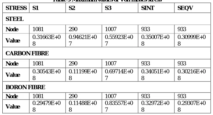
The maximum values of Von mises stress results for Steel, Carbon Fiber and Boron are as follows.
Table 5 Maximum values of Von misses stress
STRESS S1 S2 S3 SINT SEQV
STEEL
Node 1081 290 1007 933 933
Value 0.31663E+0 8 0.94621E+0 7 0.55923E+0 7 0.35007E+0 8 0.30999E+0 8 CARBON FIBRE
Node 1081 290 1007 933 933
Value 0.30543E+0 8 0.11199E+0 8 0.69714E+0 7 0.34051E+0 8 0.30216E+0 8 BORON FIBRE
Node 1081 290 1007 933 933
Value 0.29479E+0 8 0.11488E+0 8 0.83557E+0 7 0.32972E+0 8 0.29307E+0 8
5.
C
ONCLUSIONSThe development of composite leaf spring can be adoptable in place of conventional steel spring. Since it is having some tremendous advantage. This project analysed that composites can be used in place of steels for designing leaf springs to reduce weight and improved performance. In this project leaf springs 3D-modelling has done in pro-E and analysis has done in ANSYS. Also comparative study has been done between composites like carbon fibre, boron fibre and conventional steel with respect to weight and strength. From the observations and results, it is concluded that leaf spring with composite is lighter and economical than the conventional steel springs with same design specifications.
References
Volume 2, Issue 10, October 2013
Page 329
[2] Mouleeswaaran Senthil Kumar, Sabapathy Vijayarangan “Analytical and Experimental Studies on Fatigue LifePrediction of Steel and Composite Multi-leaf Spring for Light Passenger Vehicles Using Life Data Analysis” ISSN 1392–1320 MATERIALS SCIENCE Vol. 13, No. 2. 2007.
[3] Mahmood M. Shokrieh *, Davood Rezaei “Analysis and optimization of a composite leaf spring” Composite Structures 60 (2003) 317–325.
[4] J.P. Hou, J.Y. Cherruault, I. Nairne, G. Jeronimidis, R.M. Mayer “Evolution of the eye-end design of a composite leaf spring for heavy axle loads” Composite Structures Volume 78, Issue 3, May 2007, Pages 351-358.
[5] S. Vijayarangan.Fatigue of Composites–Fatigue Modulus Concept and Life Prediction Journalof Composite Materials,1986.
[6] Dharam, C. K.Composite Materials Design and Processes for Automotive Applications.The ASME Winter Annual Meeting, San Francisco, 1978.
[7] Eichhorn,et.al, Current international research in to cellulosic fibbers and composite, Review, Journal of materials science 36 (2001), pp2107-2131.
[8] Dakshraj Kothari, Rajesh Satankar “Review of Researches on Leaf Spring Regarding Use of Composite Material and Various me thods for Predicting Fatigue Life” IJCRR Vol. 4 issue 01 Jan.2012.
[9] R. W. Landgraf and R. C. Francis “Material and Processing Effects on Fatigue Performance of Leaf Springs” Congress and Exposition Cobo Hall,Detroit February 26-March 2, Vol.28 No.3 (2009), pp.351-363
[10]Kumar and Vijayarangan, Analytical and experimental studies on fatigue life prediction of steel and composite multi-leaf spring for light passenger vehicles using life data analysis, Materials science, Vol. 13, No. 2, 2007.
[11]Arora, Bhushan, and Aggarwal, Eye design analysis of single leaf spring in automotive vehicles using CAE tools, International journal of applied engineering and technology, vol.1(1),2011, pp88-97.
[12]Krishan and Aggarwal, A finite element approach for analysis of a multi leaf spring using CAEtools, Rsearch journal of recent sciences, vol.1(2), Feb.2012, pp92-96.
[13]Rajendran and Vijayarangan, Optimal design of a composite leaf spring using genetic algorithms, July 2000. [14]Venkatesan and Devaraj, Design and analysis of compoite leaf spring in light vehicles, International journal of
modern engineeringresearch, Vol.2, Issue.1, Jan-Feb 2012, pp213-218.
[15]Raghavedra.et.al, Modelling and analysisof laminated composite leaf spring under the static load condition by using FEM, International journal of modern engineering research, Vol.2, Issue.4, July- Aug.201, pp1875-1879.
[16]Kumar, Patnaik, and Yadav, Minimization of stress of parabolic leaf spring by simulated annealing algorithm, International journal of engineering research and applications, Vol.2, Issue 4, July-Aug.2012, pp457-460.
[17]Patel, Jain, and Gandhi, a Review of Effect of Material on Fatigue Life of Leaf Spring, VSRD International journal of mechanical, automobile and production engineering, vol.2(4), 2012, pp161-165.