Indoor LED Lighting Control System Using
WSN Considering User Satisfaction
R. Meenakshi
1, Dr.D.M.Yadav
2P.G. Student, Department of Electronics & Telecommunications Engineering, JSPM’s Bhivarabai Sawant Institute of
Technology & Research, Wagholi, Pune, India1
Principal, Department of Electronics & Telecommunications Engineering, JSPM’s Bhivarabai Sawant Institute of
Technology & Research, Wagholi, Pune, India 2
ABSTRACT: Nowadays, energy saving is one of the most important factor to consider. Automated lighting systems are a solution for efficient use of lighting which forms a large part of world’s total energy consumption. However, today automated lighting solution when employed in indoor environments like homes and offices are not very effective. Since indoor environment have users with different and varying requirements. This work proposes a LED lighting control system using wireless sensor networks with tunable parameters to meet twin goals of energy efficiency and user satisfaction. Users in the indoor environment can adjust the parameters through a mobile application for their needs.
KEYWORDS: LED lighting control system, minimum light intensity
I. INTRODUCTION
Energy and its efficient use are of concern due to the twin problems of depleting energy resources and its effect on the environment. Energy consumption of consumer electronics is a major contributor. Light accounts for a great part of the total energy consumption. It is estimated that approximately 20% of world’s total energy consumption [7] is due to lighting systems.
Related studies of an energy efficient lighting system have been done and are ongoing by various researchers around the world. The invention of light emitting diode (LED) results in lower energy consumption of a light, because the LED lighting device consumes 50 percent of the total energy consumption compared to the fluorescent lighting device.. The technical report from the U.S. Department of Energy shows that about 15 percent of total energy consumption can be reduced via light control based on user's living pattern. Thus the combination of LED and tailored solutions can reduce energy consumption.
User satisfaction is a more crucial factor than cost benefits due to energy saving in a house or office environment. Since the existing lighting control systems can support only on/off or dimming control according to user movement or brightness of surroundings, it is very difficult to be applied to such complex environments. In the complex environment there is a variety of control requirements needed depend on individual users and their needs. Since the existing systems are designed without considering user satisfaction, it is not appropriate to the places such as house and office where user satisfaction is the main criteria. User dissatisfaction can arise out of frequent On/Off, insufficient illumination intensity for his current work. Thus intelligent lighting control systems should be designed considering both energy efficiency and user satisfaction.
Indoor environments present a challenge in terms of the user and his activities. A general On/Off and/or preset dimming control might cause a lot of inconvenience to a user in an indoor environment like a home or office. Therefore, there is a need for a new intelligent lighting control system which should be designed considering both energy efficiency and user satisfaction.
The goals of the new efficient lighting control system design can be stated as:
-- The new intelligent lighting control system should be designed to maximize the utilization of an LED.
-- The new intelligent lighting control system should be designed to control based on the situation awareness and hence have communication capability.
-- The new intelligent lighting control system should be designed to enhance both energy efficiency and user satisfaction.
This work presents an implementation of a lighting scheme based on the above design goals for LED‘s utilizing multi sensors and wireless communication technology that can result in potential energy saving in an indoor environment while allowing the user to tune the control to his satisfaction.
II. LITERATURESURVEY
Pan et al [1] proposes a wireless sensor network-based intelligent light control system for indoor environments. The wireless sensor network is responsible for measuring current illuminations. Lighting devices (whole and local) are managed based on user activities and profiles by two requirement models – binary and continuous satisfaction.
An illumination decision algorithm and a device control algorithm were proposed to determine proper illumination and achieve desired optimization goals of the end user. Then a closed-loop device control algorithm is applied to adjust the illumination levels of lighting devices. The system requires high computational cost and provides non-friendly user interaction.
Park et al [2] proposed lighting control system based on a building automation and control network (BACnet – Building Automation and Control). The system can reduce the energy consumption for lighting loads by 40%. Within this 40% energy saving. 28% of the saving can be achieved by ON/OFF control. Twelve percent of saving can be achieved by dimming control. Primarily completely meant for building automation and is concerned with energy saving & stable operation of the network and does not consider user satisfaction.
Uhm et al [3] proposed an LED light system with light sensors, motion sensors, and network interfaces. LED light enabler communicates with context – aware middleware using an intelligent power gateway that determines the optimal power control by analysing user living patterns using sensing data obtained by devices.
In summary, this light control system can control illumination intensity of an LED light based on brightness of surrounding and movement of residents. This enabler reduces power consumption upto 58% in comparison to a basic lighting system. Energy efficiency & user satisfaction are highly dependent on user activities & the environment spaces considered.
Bellido et al [4] proposed building lighting automation system using digital addressable lighting interface (DALI) devices with wireless sensor networks. The main purpose of the system is to provide the end customer with an economically fully centralized system focuses on cost saving.
The use of DALI devices with WSN allows half-duplex communication which can provide many parameters about lighting and lamp status, this is useful for energy saving and maintenance purposes. BAC does not consider user satisfaction as criteria.
Byun et al [6] proposed an intelligent household LED lighting system considering energy efficiency and user satisfaction. The proposed system utilizes multi sensors and wireless communication technology in order to control an LED light according to the user’s state and the surroundings. The proposed system can autonomously adjust the minimum light intensity value to enhance both energy efficiency and user satisfaction. The proposed lighting system reduces total power consumption of the test bed up to 21.9%.
III.THEORETICALBACKGROUND
It is useful to analyze the operation sequence of an indoor lighting environment as shown figure-1.
Figure.1- Basic Operating Principles Source: Net
In the above figure-1,
Lmin – minimum light intensity. Lmax – maximum light intensity. Tr – rise time period of light intensity.
Tm –time period between no movement detection and that the light intensity begins to falls. Tf – fall time period of the light intensity.
If there is no motion detected, the intensity of the light has to be kept at the Minimum Light Intensity level (Lmin). When motion is detected, the intensity of the light has to increase from minimum light intensity to Maximum Light Intensity (Lmax) with the rise time (Tr) set by the user. When no motion is detected, the intensity of the light has to start reducing after a delay time(Tm) by a rate specified by fall time (Tf). Both these parameters are specified by the user.
It can be seen that,
If Tr Longer => Tm and Tf are shorter => Greater Energy saving => Higher Inconvenience
The figure-2 illustrates the comparison of amount of energy reduction and user satisfaction. The shaded portion shows the amount of energy reduction. If the rise time is more and fall time is more and the delay time is less after no movement detection, then there is a higher energy saving as illustrated by the first graph. This gives higher inconvenience to the user due to the dark environment.
Relatively second graph illustrates with a very less rise time, gradually slow decrease in fall time and more delay time. This gives lower energy saving but higher convenience to the user. User can set the parameters according to their requirement and the space environment upto to their satisfaction level.
In summary, inconvenience to users will be higher because of frequent light on/off and dark indoor environment, while energy saving is higher. Hence it is necessary to properly set the value according to space environmental characteristics (like frequent or rare user movement, work type, etc,)
IV.PROBLEMDEFINITION
Based on the objective of this work being to design an intelligent LED lighting control system which would result in energy saving as well consider user satisfaction, the following design goals can be stated:
LED Utilization
Have communication capability
Communication means should be barrier free
Control decisions based on situations
Enhance energy efficiency and user satisfaction
The above can be realized by the use of Sensors and wireless communication technology and user feedback. The technology will allow the use and control of LED based on the user’s state and surroundings.
V. SYSTEMMODEL
Intelligent lighting control system can reduce energy consumption as automatically controlling the intensity of illumination. The main features of the proposed system model are as follows and shown in figure-3.
Autonomous control based on user movement
Autonomous control based on brightness of the surroundings
Autonomous optimization of system control with the user inconvenience feedback signal.
Figure.3- Block diagram of the System Model.
To realize the above, we design the intelligent household LED lighting system with the following control and feedback elements for a single node
- a controller
- a motion detection sensor - an illumination sensor and
- a wireless communication interface and
- an algorithm to take action based on user feedback
The motion detection sensor of a single node provides a feedback on the user movement and the illumination sensor of the same node provides a feedback on the brightness of the location of the node.
controllers. Collective control of the controllers of different nodes along with user feedback provides the desired results.
Figure.4- Illustrates the overview for a typical room/hall.
A large room typical of office environments can be visualized as shown in below figure-4.
Source: Net
Figure.5- Overview of the proposed system with many LED groups
The proposed system using various sensors and wireless communication technology can reduce energy consumption via interaction with the information about user’s state and surroundings (e.g. brightness of a room). The autonomous control On/Off could lead to disturbance to residents. Thus, in order to enhance both energy efficiency and user satisfaction the proposed system autonomously optimizes the system control and state variables, especially Lmax, Lmin, Tr , Tm, and Tf.
VI.ALGORITHM
The objective of the algorithm is to derive the Lmin value, which can save energy at the maximum without causing inconvenience for users. The input to the algorithm is a signal of inconvenience and a Timer. The signal of inconvenience is the input/user feedback indicating that the lighting brightness is not sufficient. The Timer provides the interrupt after a given amount of time.
Step 1: In the first step, check whether a signal of inconvenience has occurred. If a signal of inconvenience has occurred, then
Ln = (Lmc+Ln-1)/ 2, Lmic = Ln-1, n = n + 1, and timer= T. And then check again whether a signal of inconvenience has occurred.
Step 2: Again, check whether a signal of inconvenience has occurred. If a signal of inconvenience has occurred, then Ln = (Lmc+Ln-1)/2, Lmic= Ln-1, n = n + 1, and timer= T as in Step 1. If a signal of inconvenience has not occurred, then check whether time is equal to zero (i.e. the expiration of a given amount of time, T).
Step 3: Again, check whether timer is equal to zero, if timer is equal to zero, then Ln = (Lmic+Ln-1)/2, Lmc=Ln-1, n = n + 1 and timer= T. And then, check whether Lmc – Lmic is less than 5 or not. If timer is not equal to zero, check again whether a signal of inconvenience has occurred.
Step 4-1: After check whether Lmc – Lmic is less than 5, if Lmc – Lmic is less than 5, then terminate this flowchart. If Lmc – Lmic is not less than 5, then perform the process of Step 4-2.
Step 4-2: Check whether a signal of inconvenience has occurred. If a signal of inconvenience has occurred, then Ln = (Lmc+Ln-1)/2, Lmic= Ln-1, n= n+ 1, and timer= T. If a signal of inconvenience has not occurred, then perform again from Step 3.
It is possible to derive the value of Lmin, which can save energy at the maximum with user satisfaction through the proposed algorithm.
VII. PROPOSEDIMPLEMENTATIONOFHARDWARE
Figure-6 shows the block diagram of the proposed hardware. In this proposed hardware, there are two nodes. Each node has an ARM processor, motion detection sensor, illumination sensor and a group of LED’s. A another Arm based board is used as a super controller which is used for setting the parameters and taking the input from the user if there is any dissatisfaction with light intensity. The two nodes can be set with two different parameter values. Each node displays percentage intensity separately using LCD screens.
If there is any dissatisfaction in the illumination of light for the user, then a signal of inconvenience will be sent from the user as a feedback through a mobile application. Parameters set by user will be displayed on the LCD screen and sent to the particular node.
VIII. RESULTSANDDISCUSSIONS
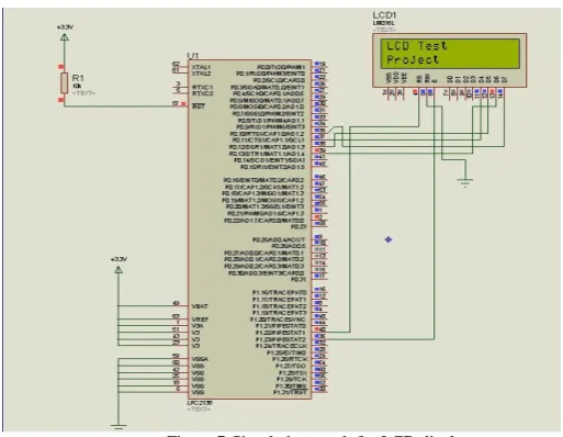
Figure 7 shows the simulation result for LCD display. To test the LCD display, it has been connected to LPC2138 microcontroller. The schematic has been designed and simulated by using Proteus software.
Figure.7-Simulation result for LCD display
To simulate the design, coding has been done using Keil4 software. The output string is displayed in two separate lines. The parameters send by the user will be displayed in the LCD display screen.
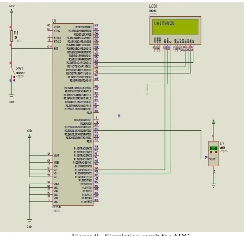
Figures 8 & 9 shows the simulation result for Analog to Digital Converter.
To test the ADC, LCD has been connected to LPC2138 microcontroller along with the temperature sensor. First it displays the text written in the code.
Figure.9 –Simulation result for ADC
Then it displays digital value corresponding to the analog value sent from the temperature sensor as shown in the figure 9. Here it has been tested with two separate commands given for two lines.
IX.CONCLUSION
Indoor environment requirements have to take into account the needs of the users User satisfaction is a more crucial factor compared to the cost benefits due to energy saving in a house or office environment. Automated lighting systems can be made effective by giving user tunable parameter in indoor environments like home and office buildings. User interaction can be made with fine adaptive control tuning along with intuitive user interface application for different mobile operating systems like Android, IOS and windows mobile.
REFERENCES
1. M.-S. Pan, L.-W. Yeh, Y.-A. Chen, Y.-H. Lin, and Y.-C. Tseng, "A WSN-Based Intelligent Light Control System Considering User Activities
and Profiles," IEEE Sensors Journal, vol. 8, no. 10, pp. 1710-1721, Oct. 2008.
2. T.-J. Park and S.-H. Hong, "Experimental Case Study of a BACnet-Based Lighting Control System," IEEE Trans. on Automation Science and
Engineering, vol. 6, no. 2, pp. 322-333, Apr. 2009.
3. Y. Uhm, I. Hong, G. Kim, B. Lee, and S. Park, "Design and implementation of power-aware LED light enabler with location-aware adaptive
middleware and context-aware user pattern," IEEE Trans. on Consumer Electron., vol. 56, no. 1, pp. 231-239, Feb. 2010.
4. F. J. Bellido-Outeirino, J. M. Flores-Arias, F. Domingo-Perez, A. Gil-de-Castro, and A. Moreno-Munoz, "Building lighting automation through
the integration of DALI with wireless sensor networks," IEEE Trans. on Consumer Electron., vol. 58, no. 1, pp. 47-52, Feb. 2012.
5. F. Leccese, "Remote-Control System of High Efficiency and Intelligent Street Lighting Using a ZigBee Network of Devices and Sensors," IEEE Trans. on Power Delivery, vol. 28, no. 1, pp. 21-28, Jan. 2013.
6. Jinsung Byun, Insung Hong, Byoungjoo Lee, and Sehyun Park, "Intelligent Household LED Lighting System Considering Energy Efficiency