www.ijiset.com
202
Design & analysis Of Bevel Gear for Dynamic and Wear
Loading using geometrical programming
Narendra Sharma, D.V.S. Chauhan
ABSTRACT
This paper is a proficient approach for solving the problem of design and analysis for Dynamic and Wear load of Bevel gear, principally to aid the industries and designers. Surrounded by the diverse optimization techniques the approach breaks new era by utilizing Geometrical Programming Technique, because this is one of the proficient and enhanced techniques to resolve non-linear equations of the complex and sensible design problems.
The research deals with the design of bevel gear train for lowest dynamic load and wear load. The load capacity of bevel gears is based on either bending or wears capacity whichever is lesser. The tangential force for passing on utmost power has been found by lowering the dynamic load or wear load as per the necessity.The arbitrary nature of design variables has been given appropriate deliberation and probability of fulfilling constraints equation has also been taken care of.
A clarifying instance of bevel gear train design has been considered. The bevel gears are designed and optimized using Geometric Programming technique, considering the nature of parameters, proper values are given to convince constraints. The problem taken is solved for optimization by lowering dynamic load on the gear as well as to lower the wear load on the gear. The manually computed results are comparefor the diverse values achieved from the software implemented.
Keywords : Gear, Bevel Gear, Geometrical programming.
INTRODUCTION
Bevel Gears
To recognize the bevel gear tooth geometry, one might first monitor the case of straight bevel gears. If the generating rack used to obtain the cylindrical gear involutes is curved in a horizontal plane into a
circular shape, it results in a crown gear which is used to derive the flank form of bevel pinion and gear. For straight bevel gears the crown gear or generating gear can be placed amid the pinion and gear assembly. Its center is located accurately at the intersection point of the pinion and gear shafts.
As a mental implement the crown gear should consist of a very thin material like aluminum foil. For all three elements it is to be in mesh at the similar time. The pinion is situated at the back surface of the crown gear and meshes with the negative teeth while the ring gear is located at the front surface of the crown gear and meshes with the positive teeth. If such an agreement is achievable then the kinematic coupling circumstances of the bevel gear set are satisfied which means the pinion and the gear can mesh with each other also.
A single outline of the generating gear generates a gear on its one surface and the mating member on its other surface. The outline and lead is instantly which causes a straight lead and an octoid outline on the generated teeth. The octoid essentially is the bevel gear analog of an involute. The octoid provides stable ratio and makes the gears insensible to displacements vertical to the pitch line.
Virtual Number of Teeth
The tooth profiles of bevel gear should be urbanized on a spherical plane. As a true expansion of a spherical surface into a plane is not possible, an estimate has to be made for which the virtual number of teeth is to be resolute. This limitation is defined as the number of teeth which a spur gear would have radius of which is equivalent to the back cone distance and having pitch of the bevel gear. This is called Tredgold’s approximation.
The virtual number of teeth is given by
TRvR=2πRRbR/P
= T/cos Ψ
www.ijiset.com
203
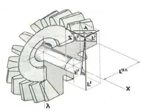
Force Analysis of Bevel GearFig 1.2 Components of Tooth Force
For force investigation of pair of mating bevel gear, it is unspecified that the total force PRNR acts on the pitch
point at the middle of the tooth width. The consequential however actually occurs somewhere between the midpoint and the back end of tooth but the fault due to above hypothesis is marginal.
Here we have represented the forces FRnR, FRaR, FRrR by PRN,R
Pa and PRrR, pressure angle φ by αRnR and pitch angle ϒ
by Ψ correspondingly. The mean tooth force PRN Ris
resolved in three equally perpendicular components. They are tangential force PRtR, radial force PRr Rand the
axial force Pa.
The tangential force is considered as following
PRt R=RR (2 MRtR/d)
Where MRt R= Transmitted torque = 60 x 10^6 (KW) /
(2πN) (N-mm)
d = Pitch circle diameter (mm)
Radial force, PRrR = PRtRtan αRnRCos Ψ
Axial force, Pa = PRtRtan αRnRSin Ψ
If the shaft angle is 90P
0
P
then the following relation holds good
Pa= PRr
Fig. 1.3 Illustration of Spiral Angle
The cases discussed above are the cases of straight bevel gear. Now we will talk about spiral bevel gear. In the known figure spiral angle is shown by Ψ but we gave denoted it by β for our ease. A range of forces acting on spiral bevel gear are given as following:
Tangential Force, PRt R=RR (2 MRtR/d)
Radial force, PRrR = PRtR(tan αRnRcos Ψ −sinβsin Ψ)/ cosβ
Where β is the mean spiral angle
Axial force, Pa = PRt R( tan αRnRsin Ψ +sinβcos Ψ)/ cosβ
Dynamic Load on Gear Tooth
The tangential force performing on the bevel gear will be PRt R= (2 MRtR/d)
The above significance of tangential constituent therefore depends upon rated power and rated speed. In addition to this, there is a dynamic load acting which can be considered by two dissimilar methods i.e. approximate estimation by means of the velocity factor in the preliminary stages of gear design and accurate calculation by Spott’s equation in ending stages.
The effective load PReffR between two meshing teeth is
given below
PReR = CRsRPRt R/ CRv
CRsR = Service factor, CRvR = velocity factor
Velocity factor for bevel gear is given as here
CRvR= 5.6 / (5.6 + √ v)
Where v is the pitch line velocity in m/s.
In the last stage of gear design, when gear dimensions are recognized, errors are particular and the quality of gear is resolute, the dynamic load is calculated by equation derived by M.F.Spotts.
Depending upon the resources of the pinion and gear, there are three equations for the dynamic load:
(i) Steel pinion with steel gears
PRdR = eNRpRTRpRbrR1RrR2R/ 2530 √ (rR1RP
2
P
+ rR2RP
2
P
)
www.ijiset.com
204
PRdR = eNRpRTRpRbrR1RrR2R/ 3785 √ (rR1RP2
P
+ rR2RP
2
P
)
(iii) Steel pinion with C.I. gears
PRdR = eNRpRTRpRbrR1RrR2R/ 3260 √ (rR1RP
2
P
+ rR2RP
2
P
)
Where
PRdR = dynamic load (N)
e = sum of error between two meshing teeth (mm)
NRpR = speed of pinion (RPM)
rR1R, rR2R = Pitch circle radii of pinion
and gear (mm)
The dynamic load is understood to be inclined at an angle αRnR to the tangent plane. The dynamic load PRdR
acts in the same direction as the resultant force P.
Tangential component of the dynamic load is PRdR Cos
αRn RCos Ψ.
The effective load is given through
PReR = CRsR PRtR + PRdRCosαRn RCosΨ
This is the effective load in the tangent direction for judgment with beam strength, or wear strength. In order to evade failure of gear tooth due to bending
PRbR > PRe
In addition to this dynamic load is also given by the equation as below:
PReR = CRsR PRtR+U21V (Ceb+PURtR)/ 21V+ (Ceb+PRtR )
Where V in the pitch line velocity
e the gear and pinion errors
b is the face width.
Wear Strength of Bevel Gear
Bevel gear is considered to be alike to a formative pinion and formative gear in a plane perpendicular to the tooth element. So the wear strength of bevel gear is given as follows:
(SRwR)RnR = b’Qd’RpRK
Where (SRwR)RnR= Wear strength perpendicular to the
tooth element
b’ = b/CosΨ = Face width along the tooth element
d’RpR = dRpR / CosΨ = Pitch circle diameter of
the formative pinion
Substituting values in the above equation, we get
(SRwR)RnR= bQdK / CosP
2
P
Ψ
The component of (SRwR)RnR in the rotation is denoted by
SRw
Therefore SRw R=RR(SRwR)RnRCos Ψ Or
SRwR= bQdK / CosΨ
Above equation is known as Buckingham’s equation of wear strength. The wear strength SRwR indicates the
maximum tangential force that the tooth can transmit without pitting breakdown. It should be always greater than the effective force between the meshing teeth. The virtual number of teeth on the pinion and gear are T’RpR & T’RgR correspondingly. The gear factor
Q for external bevel gear is through
Q = 2 T’RgR / (T’RpR + T’RgR)
The pressure angle in a plane perpendicular to the tooth element is αRnR. The factor K is given as
K = 0.16 (BHN / 100)P
2
The given equation is applicable for steel gears with 20P
0
P
normal pressure angles. In order to evade failure of gear tooth due to pitting SRwR> PReR
METHODOLOGY & PROGRAMMING
Geometric Programming is a technique for the solution a category of nonlinear Programming problems. It was introduced by Richard Duffin, Clarence Zener and Elmor Peterson. It is applied to diminish functions which are in the form of
www.ijiset.com
205
frequently reduces a complex optimization problemto one relating a set of immediate linear algebraic equations. The main drawback of the method is that it needs the objective function and the constraints in the outline of Posynomials.
Posynomial
In an engineering design condition, often the objective function (like the total cost) f(X) is described by the sum of numerous component costs URiR(X) as
f(X) = UR1R + UR2R + ………… + URNR
In many cases, the component cost Ui can be articulated as a power function
Ui = cRiRxRiRP
a1i
P
xR2RP
a2i
P
………xRnRP
ani
Where the coefficients cRiR are positive
constants, the exponents aRij Rare real constants
(positive, zero or negative) and the design parameters xR1R, xR2R………..xRnR are taken to be positive variables.
The functions like f, because of the positive coefficients variables and real exponents are known as Posynomials. For instance, f( xR1R, xR2R, xR3R) = 8 – 5xR1R
+ 21xR2R + 7xR1RP
2
P
– 3xR1RxR2R + 5xR3R is a Posynomial. If the
natural formulation of the optimization difficulty does not lead to Posynomial functions, geometric programming methods can still be used to resolve the problem by replacing the real functions by a set of empirically fitted Posynomials over a large range of the parameters xRiR.
Design & Optimization of Bevel Gear for Minimum Dynamic Load
Flow Chart of Optimizing Gear for Lowest Dynamic Load by Geometric Programming method
Design of Bevel Gear for Lowest Dynamic Load
Dynamic Load between gear teeth
The determination of the dynamic load between gear teeth is a complicated problem because of diverse assumptions involved in the design and magnitude of the errors are unknown etc. So making an allowance for all this the equation for the dynamic load is described by
PRdR= [2e√ (K.mReR)]/t ……….(4.1)
Where e = combined error of mating of two gears (mm)
t = time for passage of a tooth through the contact zone
t = 60/ (T.N) seconds
where T = No. of teeth of gear
N = speed of gear in RPM
K = spring constant for the pair of machine gear teeth
If both gears are made of steel, then K = 11500 bN/mm
If gear is made of steel and pinion of C.I., then K =8000 bN/mm
mReR = Equivalent mass for two gears (Kg)
www.ijiset.com
206
The spring constant of a pair of gear will vary while atooth is passing through the contact cone since one, two or sometime more, pair may be contact at dissimilar times. During the central portion of the passage a single pair is in contact which must carry the whole load.
The dynamical system of two gears is considered as the masses mR1R and mR2R.concentrated at the pitch
circles connected by a spring comprising of two teeth. For such a system, the effectual mReR is given the
below equation
1/mReR = 1/mR1R + 1/mR2
The mass m1 of the pinion and m2 of gear is equal to
mR1R= π rR1RP
2
Pb γR1R/2g
mR2R= π rR2RP
2
Pb γR2R/2g
Where b = thickness in axial direction (mm)
g = Acceleration due to gravity
= 9806.6 mm/sP
2
γR1R, γR2R = weight density of pinion and gear
respectively in N/mmP
3
Considering steel pinion and steel gear combination and taking γR1R= γR2R = 0.0000768 N/mmP
3
Then 1/mReR = 81270000/b * [(rR1RP
2
P
+ rR2RP
2
P
)/ rR1RP
2
P
.rR2RP
2
P
]
Substituting all these in Eq. (4.1) we get,
PRdR = (eTR1RNR1Rb rR1R rR2R) / (2530*√ (rR1RP
2
P
+ rR2RP
2
P
))
Force Analysis Of Bevel Gear
The resultant force P acting on the tooth of a bevel gear is resolved into three components PRtR, PRrR, and PRa Ras shown in fig 4.1 Where PRtR = Tangential
component (N)
PRrR = Radial component
(N)
PRaR = Axial or Thrust
component (N)
Fig 4.1 Components Of Tooth Force
From triangle ABC
PRrR= P Sin αRnR ……….. (a)
BC = P Cos αRnR ……….. (b)
From triangle BDC
PRaR= BC Sin Ψ = P Cos αRnRSin Ψ ………. (c)
PRtR= BC Cos Ψ = P Cos αRn RCos Ψ ……… (d)
From eqn. (c) and (d)
PRaR = PRtRtan Ψ ……… (3)
From eqn. (a) and (b)
PRrR = PRtR{tan αRnR/ Cos Ψ} ……… (4)
The cases explained above are the cases of straight bevel gear. Now we will talk about spiral bevel gear. Different forces acting on spiral bevel gear are given as following:
Tangential Force,PRt R=RR (2 MRtR/d)
Radial force, PRrR = PRtR( tan αRnRcos Ψ −sinβsin Ψ)/
cosβ
Where β is the mean spiral angle
Axial force, Pa = PRtR( tan αRnR sin Ψ +sinβcos Ψ)/
cosβ
The tangential component is calculated from the relationship
PRt R= (2 MRtR/d)
Where MRt R= Transmitted torque = 60 x 10^6 (KW) /
(2πN) (N-mm)
d = Pitch circle diameter (mm)
The above equation is utilized to resolve the three components of the resulting tooth force
www.ijiset.com
207
approximate estimation by means of the velocityfactor in the preliminary stages of gear design and precise calculation by Spott’s equation in final stages.
The effective load PReR between two meshing teeth is
given by
PReR = CRsRPRt R/ CRv
CRsR = Service factor, CRvR = velocity factor
Velocity factor for bevel gear is given as
CRvR= 5.6 / (5.6 + √ v)
Where v is the pitch line velocity in m/s.
In the last stage of gear design, when gear dimensions are notorious, errors are specific and the quality of gear is determined, the dynamic load is deliberated by equation derived by M.F.Spotts.
Depending upon the materials of the pinion and gear, there are three equations for the dynamic load are
(i) Steel pinion with steel gears
PRdR = eNRpRTRpRbrR1RrR2R/ 2530 √ (rR1RP
2
P
+ rR2RP
2
P
)
(ii) C.I. pinion with C.I. gears
PRdR = eNRpRTRpRbrR1RrR2R/ 3785 √ (rR1RP
2
P
+ rR2RP
2
P
)
(iii) Steel pinion with C.I. gears
PRdR = eNRpRTRpRbrR1RrR2R/ 3260 √ (rR1RP
2
P
+ rR2RP
2
P
)
Where
PRdR = dynamic load (N)
e = sum of error between two meshing teeth (mm)
NRpR = speed of pinion (RPM)
rR1R, rR2R = Pitch circle radii of pinion
and gear (mm)
The dynamic load is understood to be inclined at an angle αRnR to the tangent plane. The dynamic load PRdR
acts in the same direction as the resultant force P.
Tangential component of the dynamic load is PRdR Cos
αRn RCos Ψ.
The effective load is given by
PReR = CRsR PRtR + PRdRCosαRn RCosΨ
This is the effective load in the tangent direction for evaluation with beam strength, or wear strength. In order to avoid breakdown of gear tooth due to bending
PRbR > PRe
Where PRb R= Bending load of the gear and is
given by
PRbR = mRnRbσRbRY(1-b/AR0R)/cosβ
Where mRnR = Normal module of gear(mm)
b = Face width of gear(mm)
σRb R= Safe bending stress(N/mmP
2
P
)
Y = Lewis form factor based on Virtual number of teeth
AR0R=Back Cone Distance
PRb = R2𝜋rR2RbσRbRY.cosΨ(1-b/AR0R)/NR2R cosβR
R………..(5)
Or PRbRNR2R cosβ /R R2𝜋rR2RbσRbRY.cosΨ(1-b/AR0R)R R≤R
R1………(6)
The load capacity of pair of gear is based on bending capacity. The tangential force PRt R for transmitting the
maximum power is found by minimized PRd R and can
be spoken by considering the service factor as well as the factor of security as unity
The equation is given by:
PRe R= PRt R + PRd
As PRt = RPReR- PRd
The problem now is to reduce objective function given by equation
PReR = CRsR PRtR + PRdRCosαRn RCosΨ………..
Satisfying the constraint equation
PRbRNR2Rcosβ /RR2𝜋rR2RbσRbRY.cosΨ(1-b/AR0R)RR≤R R1
Geometric Programming Implementation
If the design parameters are rR1R and rR2R are taken as
random variable because of mechanized tolerance etc. their value will vary about mean value. If these random variables follow normal distributions the mean values and standard deviation are rR1R, rR2Rand σR1R,
www.ijiset.com
208
equivalent deterministic form is given by equationPRdDR = PRe R+ [∑ (𝑛
𝑖=1 dPRe R/drRiR)P
2
P
rRiR. σP
2
PRriR] P
½
P
(4.2)
If the constraint equation gRjR is satisfied with a
probability PRj Rand normal variation for probability PRjR
is given ΦRjR (PRjR) then the new constraint equation in
equivalent deterministic form is given by
gRjdR = gRjR - ΦRjR (PRjR) [∑ (
𝑛
𝑖=1 dPReR/drRiR)P
2
P
rRiR. σP
2
PR
riR] P
½
P (4.3)
Lastly the problem reduces to minimize the objective function given by equation (4.2) fulfilling constraint equation (4.3)
Design & Optimization of Bevel Gear for Minimum Wear Load
Flow Chart of Optimizing Gear for lowest Wear Load By Geometric Programming method
Design of Bevel gear for Lowest Wear Load
Wear Strength of Bevel Gears
Bevel gear is measured to be equal to a formative pinion and formative gear in a plane perpendicular to the tooth element. So wear strength of bevel gear is given as
(SRwR)RnR=b’Qd’RpRK
………(5.1)
Where (SRwR)RnR= Wear strength perpendicular to the
tooth element
b’ = b/CosΨ = Face width along the tooth element
d’RpR = dRpR / CosΨ = Pitch circle diameter of the
formative pinion
Substituting these values in the above equation, we get
(SRwR)RnR=bQdK / CosP
2
P
Ψ ……….(5.2)
The component of (SRwR)RnR in the rotation is denoted by
SRw
Therefore SRw R=RR(SRwR)RnRCos Ψ
Or SRwR=bQdK/CosΨ
………(5.3)
Above equation is known as Buckingham’s equation of wear strength. The wear strength SRwR indicates the
maximum tangential force that the tooth can pass on without pitting failure. It should be always more than the efficient force between the meshing teeth. The virtual number of teeth on the pinion and gear are T’RpR
& T’RgR correspondingly. The gear factor Q for
external bevel gear is given through
Q= 2 T’RgR / (T’RpR + T’RgR)
……….(5.4)
The pressure angle in a plane perpendicular to the tooth element is αRnR. The factor K is given through
K = 0.16 (BHN / 100)P
2
The above equation is appropriate for steel gears with 20P
0
P
normal pressure angles. In order to evade breakdown of gear tooth due to pitting
SRwR> PReR
Force Analysis of Bevel Gear
The wear load on bevel gear is understood to be at an angle αRn Rto the tangent plane as shown in fig. 4.1 in
last chapter
Referring to fig we have
SRrR= S Sin αRnR ……….. (a)
BC = S Cos αRnR ……….. (b)
From fig we have
www.ijiset.com
209
SRtR= BC Cos Ψ = S Cos αRn RCos Ψ ……… (d)From eqn. (c) and (d)
SRaR = SRtRtan Ψ ……… (e)
From eqn. (a) and (b)
SRrR = SRtR{tan αRnR/ Cos Ψ} ……… (f)
The tangential component of wear strength is considered from the association
SRt R= (2 MRtR/d)
Where MRt R= transmitted torque (N-mm)
d = pitch circle diameter (mm)
Where MRtR= 60 x 10^6 (KW) / (2πN) (N-mm)
The above equation is used to conclude the three components of the resultant tooth force.
The direction thrust components depend upon the hand of the pitch cone angle, on the direction of rotation and on whether the driving or driven gear is under concern.
Consequently tangential component of the dynamic load is given by
SRdRCos αRn RCos Ψ
And effective load is given by
SReR = CRsR SRtR + SRdR CosαRn RCosΨ
……….(g)
Where SRdR is calculated in a same fashion as PRd.
This is one effective load on the tangential direction for evaluation with beam strength.
In order to evade breakdown of gear tooth due to bending
SRbR≥SRe
RR Where
SRb R= Bending load of the gear and is given
by
SRbR = mRnRbσRbRY(1-b/AR0R)/cosβ
Where
mRnR = Normal module of gear(mm)
b = Face width of gear (mm)
σRb R= Safe bending stress(N/mmP
2
P
)
Y = Lewis form factor based on Virtual number of teeth
AR0R=Back Cone Distance
SRb = R2𝜋rR2RbσRbRY.cosΨ(1-b/AR0R)/NR2
R………..(h)
Or SRbRNR2R/R R2𝜋rR2RbσRbRY.cosΨ(1-b/AR0R)R R≤R R1
………(i)
The load capacity of pair of gear is based on bending capacity. The tangential force StRRfor passing on the
maximum power is found by minimized SRd Rand can
be spoken by considering the service factor as well as the factor of safety as unity
The equation is given by:
SRe R= SRt R + SRd
As SRt = RSReR- SRd
The problem now is to reduce objective function given by equation
SReR = CRsR SRtR + SRdRCosαRn RCosΨ ………..(j)
Satisfying the constraint equation
PRbRNR2R/RR2𝜋rR2RbσRbRY.cosΨ(1-b/AR0R)RR≤R R1
Geometric Programming Implementation
If the design parameters are rR1R and rR2R are in use as
random variable because of manufacturing tolerance etc. their value will fluctuate about mean value. If these random variables chase normal distributions the mean values and standard deviation are rR1R, rR2Rand σR1R,
σR2R correspondingly, then new objective function in
alike deterministic form is given by equation SRdDR = SRe R+ [∑ (
𝑛
𝑖=1 dSRe R/drRiR)P
2
P
rRiR. σP
2
PRriR] P
½
P
……....(5.3.1)
If the constraint equation gRjR is fulfilled with a
probability SRj Rand normal variation for probability SRjR
is given ΦRjR (SRjR) then the new constraint equation in
equivalent deterministic form is given by gRjdR=gRjR - ΦRjR (SRjR) [∑ (𝑛
𝑖=1 dSReR/drRiR)P
2
P
rRiR. σP
2
PRriR] P
½
P
…..(5.3.2)
www.ijiset.com
210
RESULTS AND DISCUSSIONThe software is implemented for obtaining the optimum design of bevel gear with lowest dynamic load and wear load as optimization standard. Analysis of the software representation was done with the help of manually considered results.
Analysis of result of design of bevel gear
and optimizing it for lowest dynamic load
As shown in flowchart in section 4.1 of chapter 4, the user has to input a variety of parameters i.e. the desired gear ratio, module of gears and pitch cone angle of the gear. The software for design of bevel gear was tested for diverse values of modules of gear keeping all other parameters as constant.
Among all the parameters tested the software is compared for its compatibility with the
mathematically solved example. In the given problem, for given module the gear under design concern will have 9 diverse outputs for 9 diverse values of wR2R which fluctuates between 0.6 and 1.4 for
a selected value of weight wR2R = 1.0, the result
computed mathematically is similar as that of what we have got from the output of the computer program within allowable bound of error. Hence it can be safely concluded that the software developed serves its purpose of determining the gear design parameters for exacting material and power transmission with minimization of dynamic load of gear.
But, the gear dimensions computed are not its optimized values. To optimize the computed gear parameters, a constraint equation is utilized to examine the design values. It has been found that not all the gear dimensions computed for a given set of input has optimum values of gear dimensions. Only those values of radius of gear, rR2R will be optimum
values of gear which are greater than or equal to 194.25 mm.
Comparing our program for m = 3 and gear ratio = 4, only few gear radius, rR2 forR wR2 Requal to 1.1, 1.2, 1.3,
1.4 satisfies the constraint equations and hence they are the optimum value of gear radius satisfying the constraint and hence any of values can be selected for an optimized values of gear radius satisfying all design circumstances in the given problem. It can be accomplished from the results that:
Designing of gear for lowest dynamic load is free of hardness of gear material.
Not all the computed radii of gear, rR2 Rare
optimized values. For optimization it must convince the constraint equation.
For a predefined weight wR2 Rthe value of
radius rR2R increases with increase in the value
of the module of gear.
For lower values of module, few values of rR2R are in optimized choice. And as the values
of module increases the range will also increase. It is experiential that module m = 4 and above the optimized values of rR2 Rdoes
not drop below for wR2R = 1.0. Therefore for
higher values of module, we don’t have optimized value of rR2R for lower values of
weight wR2R i.e. wR2R = 0.90 or less.
Analysis of result of design of bevel gear and optimizing it for lowest wear load
As shown in flowchart in section 5.1 of chapter 5, the user has to input the diverse parameters i.e. the desired gear ratio, module of gears, pitch cone angle of the gear and BHN. The software for design of bevel gear was tested for diverse values of modules of gear keeping all other parameters as steady.
Surrounded by all the diverse parameters, i.e. gear ratio, pitch angle and BHN value, the software is compared for its compatibility with the manually calculated results. In the given problem, for given module the gear under design contemplation will have 9 different outputs for 9 different values of wR2R
which varies between 0.6 and 1.4.
For a chosen value of weight wR2R = 1, the result
estimated manually is same as that of what we have got from the output of the computer geometric program within permissible limit of error. Hence it can be safely accomplished that the software developed serves its function of determining the gear design parameters for particular material and power transmission with minimization of wear load of gear.
But, the gear dimensions estimated are not its optimized values. To optimize the calculated gear parameters, a constraint equation is used to examine the design values. It has been found that not all the gear dimensions calculated for a given set of input has optimum values of gear dimensions. Only those values of radius of gear, rR2R will be optimum values of
gear which are greater than or equal to 143.57 mm.
Comparing our program for m = 3, BHN = 300 and gear ratio = 4, only few gear radius rR2 Rfor wR2R 1.1, 1.2,
www.ijiset.com
211
constraint and hence any of values can be selected foran optimized values of gear radius satisfying all design conditions in the given problem. It can be accomplished from the results that:
Not all the calculated radius of gear rR2 Ris
optimized values. For optimization it must satisfy the constraint equation.
For a given weight wR2 Rthe value of radius
rR2R increases with increase in the value of
the module of gear.
For smaller values of module, few values of rR2 Rare in optimized range. And as the
values of module increases the range will also increase.
Designing of gear for minimum dynamic load is dependent of hardness of gear material. For a given module as the BHN number increases the number of radius of gear rR2 Rfalling in the range in the
optimized range decreases.
Limitations of Software
Following are the limitations of software:
1. Software is developed for a specific problem of gear design, with a given material.
2. Software is developed for a given power to be transmitted from the gear train so no flexibility of power is there in the software
Conclusion
The software implemented in this project will aid in making judgments concerning the design of bevel gear and optimizing it for lowest dynamic and wear load. The characteristic of the software is that in order to integrate subjectivity, the judgment maker can provide its own design parameters, such as pitch angle of the gear, module, gear ratio, BHN.
The thesis presents a bevel gear design method based on Geometric Programming Technique of optimization which is a conception till now not employed in the bevel gear designing problem. The literature survey helped in knowing about the efforts being carried out in the field of gear designing and Geometric Programming Technique. It recognizes the requirements for, and processes the information about relative significance of all design parameters for given relevance, without which inter – parameter variable comparison could not be accomplished. It productively presents the results of this information concerning the difference in these design parameters
of gear in order to determine in the appropriateness for given relevance.
U
BIBLIOGRAPHY
1. BEOHAR S.B.L and SINGH G.S., “Optimum Gear
Train Design for Minimum Dynamic Loading”, proceedings of National Conference on Operational Research in Modern Technology, Year 1996, Page –A-56.
2. CARROLL R. K. and G.E. JOHNSON,
“Dimensionless Solution to the Optimal Design of Spur Gear sets” , Transactions of ASME, Journal of Machine design, Year -1989, Vol. – 111, Page – 290
3. PALAMBROS P. Y., “Monotonicity in Goal and
Geometric Programming” Transactions of ASME, Journal of Mechanical Design, Year 1982, Vol. – 104, Page – 108
4. POMREHN L.P and PAPALAMBROS
P.Y.,“Discrete optimal design formation with
application to gear train Design”. Transaction of ASME, Journal of Mechanical Design, Year – 1995,Vol – 117, Page - 419.
5. RAO A.C., “Synthesis of 4 – bar Function Generator
using Geometric Programming”, Journal of Mechanism and Motion Theory, Year 1979, Vol. – 14, Page – 141.
6. RAO S.S, “Optimization – Theory and Application”,
Printed by Wiley Eastern Limited, New Delhi, Year – 1985.
7. SEIREG ALI, “Computer optimization of Gear
Design”, Transaction of ASME, Journal of Mechanical design, year – 1981, Vol – 103, Page – 6.
8. SANQER D.J. and WHITE.G.,“Synthesis of
Composite gear Trains”, Journal of Mechanism, Year 1971, Vol – 6, Page – 143.
9. JAIN R.C, BEOHER S.B.L and OJHA S.L,
“Optimum Design of a hollow shaft for Maximum torque Transmission by stochastic Signomial Geometric Programming”. Journal of Institute of Engineers (India), Mechanical Engineering Division, Year - 1988, Vol. – 69, Page – 98.
10. MAHADEVAN K and REDDY K.B. “Design Data
Hand Book”,Published by CBS Publishers and Distributors, Delhi, Year 1993.
11. V.B.BHANDARI., “Design of machine elements”.
Printed by Tata McGraw Hill Publishing Company Ltd., New Delhi.
12. RAO S.S., “Optimization-Theory and Application”,
Printed by Wiley Eastern Ltd., New Delhi.
13. MAITRA G.M., “Hand book of Gear Design”,
Published by Tata McGraw Hill Publishing Company Ltd., New Delhi.
14. DUDELY D.W., “Handbook of Practical Gear
Design”, Printed at Tata Mc Graw Hill 49TPublishing
Company Ltd., New Delhi, Year – 1984.
15. IBRAHIM GUNEY and ERSOY, “An application of
Geometrical Programming ”, International journal of Mechanical and Mechatronic Engineering, Vol. 2, Num .2, Page 157 – 161.
16. B. O. Akinnuli1 , O. O. Agboola1* and P. P.
Ikubanni1 Parameters Determination for the Design of
Bevel Gears Using Computer Aided Design (Bevel CAD) 20 April 2015
17. JIHUI LIANG, 2 LILI XIN“Dynamic simulation of
spiral bevel gear based on solidworks and adams” January 2013. Vol. 47 No.2
18. HIROFUMI SENTOKU AND TOMONOBU ITOU,
www.ijiset.com