A Compact Broadband Printed Circular Slot Antenna with Stair
Shaped Ground Plane
Baudha Sudeep1, * and Kumar V. Dinesh2
Abstract—This is the first communication reporting a compact broadband printed circular slot antenna with stair shaped ground plane in which bandwidth is enhanced mainly in the lower frequency band on adding 19 strips at regular space intervals in the partial ground plane. The impedance matching at specific band (7.1–8.4 GHz) takes place as a result of circular slot in the patch. The proposed structure is printed on an FR4 substrate withεr = 4.3 and 0.025 loss tangent over a compact volume of 20×25×1.5 mm3. The impedance bandwidth (S11<−10 dB) of the proposed antenna is 133.7% (3.0–
15.1 GHz). The antenna exhibits 4.9 dB peak gain and 74% peak radiation efficiency in the operating band. Satisfactory results and such a simple and easy to fabricate design with compact space make the proposed antenna a suitable choice for UWB applications, 5.2/5.8 GHz WLAN bands, 3.5/5.5 GHz Wi-MAX bands, X band (8–12 GHz) and other wireless communication systems. Measured and simulated results are in good agreement, affirming the simulation process. Omnidirectional radiation patterns are generally observed in the operating band of the designed antenna.
1. INTRODUCTION
Recent research and development in the world of wireless communication suggests use of antenna structures which are easy to fabricate and possess qualities such as broad bandwidth, high gain, high efficiency and good radiation patterns. Printed monopole antennas are ideal candidate for these qualities. Slot cutting techniques (circular, rectangular, elliptical, square etc.) have been suggested for bandwidth enhancement of patch antenna [1]. Semi-circular patch with tapered microstrip line and trapezoidal partial ground plane for large impedance bandwidth is suggested [2]; bandwidth enhancement is mainly achieved due to tapered microstrip line whereas trapezoidal ground plane helps in impedance matching. Dual broad band behaviour and miniaturization have been achieved by adding parasitic slot and patch in the ground plane [3]. Bandwidth enhancement and band notch behaviour by cutting T and C shaped slots in rectangular patch [4] and semi-circular slotted patch with ultra wide band [5] have been reported recently. Antenna with U-Shaped Slit and Rectangular Parasitic Patches shows considerably large amount of fractional bandwidth (139%) covering frequencies from 2.9 to 16.3 GHz [6]. Antennas with radiation path, incomplete ground plane slots and arc shape have been suggested for UWB application [7, 9–11].
Bandwidth enhancement has been reported due to introduction of curved shaped slot in the radiating patch [8] and truncation of the corners and cutting symmetric circular slots in the radiating patch [12], bandwidth in the lower operating range is enhanced as a result of mode splitting phenomenon. Monopole slot antennas with parasitic elements and strip line feed for broadband behaviour are introduced [13–16]. Size of the structures proposed above is comparatively large (of the order of
Received 3 December 2017, Accepted 28 January 2018, Scheduled 7 March 2018 * Corresponding author: Baudha Sudeep ([email protected]).
impedance bandwidth of the proposed structure is consistently reported as 133.7% (3.0–15.1 GHz).
2. ANTENNA GEOMETRY AND PERFORMANCE
The proposed structure is printed on an FR4 substrate with εr = 4.3 and 0.025 loss tangent over a compact volume of 20×25×1.5 mm3. Graphical demonstration along with various parameter tags of the proposed antenna is shown in Figure 1; whereas the dimensional descriptions are presented in Table 1. Ground plane with strips is printed on one side and patch with circular slot is on the other side of the substrate. The proposed antenna is evolved from simple antenna in three steps as shown in Figure 2. In step one, there is simple antenna with partial ground plane and patch is chosen with appropriate dimensions. Strips at regular offset space are added in step two for excitation of lower order resonances. Finally in step three, a circular slot is cut out from the patch for better impedance matching. Simulation is performed using CST (computer simulation tool), a standard Finite integration technique (FIT) based commercial electromagnetic simulator.
Simulated return loss (Magnitude ofS11) comparing the spectral behaviour of the simple antenna,
simple antenna with strips and proposed antenna is demonstrated in Figure 3. It is clear that, initially in case of simple antenna the impedance bandwidth is 61.8% (9.5–18 GHz); on adding strips in the ground plane (antenna with strips) the corresponding impedance bandwidth has improved to 133.7%
(a) (b) (c)
Figure 1. The proposed antenna configuration. (a) Top view. (b) Bottom view. (c) Side view.
Figure 2. Evolution of the proposed antenna from simple antenna.
Table 1. Parameter value of different sections of the proposed antenna (All dimensions are in millimeters).
a b c d g h m r s w x
Figure 3. Simulated return loss (Magnitude of S11) comparison of simple antenna, simple antenna
with strips and proposed antenna.
(3.0–15.1 GHz) but a band rejection (7–8.5 GHz) is observed in this band. Now to cover this omitted band a circular slot in the patch is cut out (proposed antenna). Finally the impedance bandwidth of the proposed antenna is reported as 133.7% (3.0–15.1 GHz) consequent to excitation of lower order resonance caused due to strips in the ground plane as well as impedance matching resulting from circular slot in the patch.
3. EFFECT OF STRIPS AND SLOT 3.1. Effect of Strips in the Ground Plane
Bandwidth enhancement of the proposed antenna is mainly due to addition of strips in the partial ground plane. Strips of size 7×1 mm2 are added sequentially at an offset position of 1 mm as shown in Figure 1. Effect on the return loss (magnitude of S11) on increasing number of strips in the ground
plane is illustrated in Figure 4. In the beginning, when the number of strips is increased from 1 to 5, it is found that impedance bandwidth starts enhancing at lower band and when number of strips reaches to 5, broadband behavior is observed as lower order resonance gets excited as evident in Figure 4(a). On further increasing strips from 6 to 10, the bandwidth starts degrading as shown in Figure 4(b), this is because of impedance mismatch caused by location of strips in the central position of the ground. Exact dual band nature has been observed in most of the cases when strips are increased from 11 to 15 due to excitation of lower order resonances as visible in Figure 4(c). Now the bandwidth response of the antenna starts at lower resonances as number of strips is increased from 16 to 19. It is well illustrated from Figure 4(d) that at 19 strips, the impedance bandwidth of the antenna is attained to 133.7% (3.0–15.1 GHz) but there is a range of frequency (7–8.5 GHz) in which return loss (Magnitude of S11) goes above −10 dB line, due to mismatch in this particular range. There is a need to match
impedance in 7–8.5 GHz frequency range for covering the desired bandwidth.
3.2. Effect of Circular Slot in the Patch
Circular slot in the patch acts as a key factor in impedance matching of the proposed antenna. On introducing strips in the ground plane impedance bandwidth reaches to 133.7% (3.0–15.1 GHz), however there is an impedance mismatch in the range 7–8.5 GHz. This mismatch is overcome by cutting a circular slot in the patch of the antenna at appropriate location. The diameter of the circular slot sensitizes the return loss of the proposed antenna. Return loss (Magnitude of S11) of the proposed antenna with
different values of r is shown in Figure 5. On increasing the diameter of the slot to 6 mm, the impedance matching has been achieved in the range 7–8.5, and beyond 6 mm, the value of S11 reaches above
(c) (d)
Figure 4. Simulated return loss (Magnitude of S11) of the proposed antenna with different numbers
of strips in ground plane, (a) 1–5 strips, (b) 6–10 strips, (c) 11–15 strips, (d) 16–19 strips (All other parameters are same as in Table 1 except circular slot, as in this case there is no circular slot in the patch).
Figure 5. Simulated return loss (Magnitude ofS11) comparison of the proposed antenna with different
values ofr (All other parameters are fixed and have same values as in Table 1).
4. SIMULATED AND MEASURED RESULTS
The proposed antenna is printed using LPKF PCB prototyping machine on an FR4 substrate with
εr = 4.3 and 0.025 loss tangent and Agilent Vector Network Analyzer (VNA) is used for measuring return loss and radiation patterns with a 50 Ω SMA connector connected for feeding. Figure 6 shows measured and simulated return loss (Magnitude of S11) of the proposed antenna. Both results are in
Figure 6. Simulated and measured return loss along with photograph of the proposed antenna.
(a) (b)
Figure 7. Input impedance variation of simple antenna, simple antenna with strips and proposed antenna. (a) Real part. (b) Imaginary part.
introduction of strips in the ground plane and a circular slot in the patch.
Impedance matching is an important aspect of any antenna structure. Input impedance variation of simple antenna, simple antenna with strips and proposed antenna is shown in Figure 6. From the real part (Figure 7(a)) of the input impedance, it is observed that in case of simple antenna impedance is far away from 50 Ω for frequencies below 9.5 GHz. On adding strips to the ground plane (simple antenna with strips), the impedance is normalized to 50 Ω and on further cutting a circular slot (proposed antenna) in the patch the structure finally shows impedance close to 50 Ω in the entire band of operation (3.0–15.1 GHz). Inductive behaviour of simple antenna is observed in frequencies below 9.5 GHz as shown in Figure 7(b), this inductive behaviour is compensated by adding strips in the ground plane (simple antenna with strips) and cutting a circular slot in the patch (proposed antenna).
Frequency versus gain and radiation efficiency performance of the proposed antenna is depicted in Figure 8. Gradual increment in gain is observed with respect to frequency, which is in conformity with the behaviour of monopole antennas. At higher frequencies electrical size of antenna structure increases; as a result the directional properties are enhanced. The peak gain of the proposed antenna is 4.9 dB in the operating range of frequencies. Radiation efficiency varies from 63 to 74% in the operating band. Contrary to gain response radiation efficiency gradually decreases with respect to frequency. This gradual decrement might be because in most of the materials losses (conduction and dielectric losses) are increased with increase in frequency.
Figure 8. Gain (dB) and radiation efficiency of the proposed antenna.
(a) (b)
(c) (d)
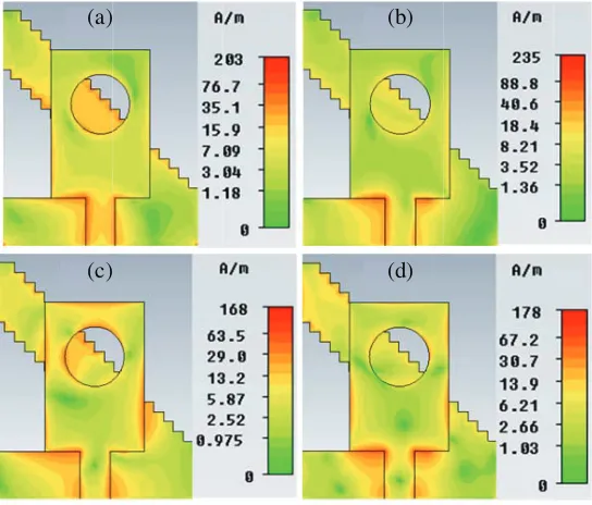
Figure 9. Surface current distribution of the proposed antenna at (a) 3.6 GHz, (b) 5.9 GHz, (c) 9.3 GHz, (d) 13 GHz.
order resonances are visible for 9.3 and 13 GHz frequencies. Current concentration is comparatively lower at the edges of the patch for 3.6 and 5.9 GHz frequencies. Lower order resonances are visible in this case. At these frequencies strips and the circular slot contributes to radiations from the structure. Conclusively, it indicates that strips in the ground plane and circular slot in the patch result in lower order resonance as well as contribute to radiations.
(a) (b)
(c) (d)
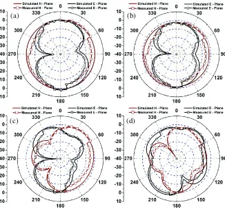
Figure 10. Simulated radiation pattern of the proposed antenna at (a) 3.6 GHz, (b) 5.9 GHz, (c) 9.3 GHz, (d) 13 GHz.
5. CONCLUSION
In this study a compact broadband printed antenna with stair-shaped ground plane and a circular slot in the patch is presented and investigated. Bandwidth enhancement is reported in the lower band of operation. Strips are added sequentially at offset position in the ground plane and a circular slot is cut into the patch without changing the dimensions of simple antenna. Bandwidth enhancement results on adding strips in the ground plane due to excitation of lower order resonances and circular slot helps in impedance matching at 7–8.5 GHz. The reported impedance bandwidth of the proposed antenna is 133.7% (3.0–15.1 GHz). The peak gain and radiation efficiencies are 4.9 dB and 74%, respectively. Simulated return loss (Magnitude ofS11) and radiation patterns of the proposed structure are in close
agreement. Simple and easy to fabricate design with compact space makes the proposed antenna suitable for UWB applications, 5.2/5.8 GHz WLAN bands, 3.5/5.5 GHz Wi-MAX bands, X band (8–12 GHz) and other wireless communication systems.
REFERENCES
1. Wong, K. L.,Compact and Broadband Microstrip Antennas, John Wiley & Sons, New York, 2002. 2. Samsuzzaman, M. and M. T. Islam, “A semi-circular shaped super wideband patch antenna with high bandwidth dimension ratio,”Microwave and Optical Technology Letters, Vol. 57, No. 2, 445– 452, Feb. 2015.
8. Baudha, S. and D. K. Vishwakarma, “Bandwidth enhancement of a planar monopole microstrip patch antenna,”International Journal of Microwave and Wireless Technologies, No. 12, Dec. 2014. 9. Karli, R., H. Ammor, J. Terhzaz, M. Chaibi, and A. M. Sanchez, “Design and construction of miniaturized UWB microstrip antenna with slots for UWB applications,” Microwave and Optical
Technology Letters, Vol. 57, No. 2, 460–463, Feb. 2015.
10. Lu, J. H. and C. H. Yeh, “Planar broadband arc-shaped monopole antenna for UWB system,”
IEEE Trans. Antennas Propag., Vol. 60, No. 7, 3091–3094, Jul. 2012.
11. Ray, K. P., S. S. Thakur, and A. A. Deshmukh, “Slot cut printed elliptical UWB monopole antenna,” Microwave and Optical Technology Letters, Vol. 56, No. 3, 631–635, Mar. 2014.
12. Baudha, S. and D. K. Vishwakarma, “Corner truncated broadband patch antenna with circular slots,”Microwave and Optical Technology Letters, Vol. 57, No. 4, 845–849, Apr. 2015.
13. Sze, J. Y. and K. Wong, “Bandwidth enhancement of a microstrip line-fed printed wide-slot antenna,” IEEE Trans. Antennas Propag., Vol. 49, No. 7, 1020–1024, Jul. 2001.
14. Jan, J. Y. and J. W. Su, “Bandwidth enhancement of a printed wide-slot antenna with a rotated slot,” IEEE Trans. Antennas Propag., Vol. 53, No. 6, 2111–2114, Jun. 2005.
15. Jan, J. Y. and L. C. Wang, “Printed wideband rhombus slot antenna with a pair of parasitic strips for multiband applications,” IEEE Trans. Antennas Propag., Vol. 57, No. 4, 1267–1270, Apr. 2009. 16. Sung, Y., “Bandwidth enhancement of a microstrip line-fed printed wide-slot antenna with a