High Speed and Cost Efficient Adaptive
Equalizer for ISI Removal
Chanpreet Kaur1
ME student, ECE Department. NITTTR sector 26, Chandigarh
Rajesh Mehra2
Assistant Professor, ECE Department. NITTTR sector 26, Chandigarh
Abstract :
This paper includes an efficient approach to design and implement a high speed and area efficient Adaptive Equalizer with LMS algorithm for ISI removal. In telecommunication, Intersymbol interference (ISI) is caused by multipath propagation. Therefore, the main aim is of designing the transmitter and receiver is to minimize the effects of intersymbol interference. Here output of the model is compared for different values of µ (step size) of LMS algorithm. Then the proposed model is synthesized with ISE 10.1, simulated with Modelsim and implemented on Virtex2 based xc2vp30-7ff896 target device. The result shows that algorithm with 0.005 step size has best constellation diagram and less MSE value than the step size of 0.001. The proposed model has the advantages of reduction in ISI using simple and less computational complex LMS algorithm along with enhanced performance in terms of speed, cost and area with existing results.
Key Words: FPGA, FSE, ISI, LMS, MSE. 1. Introduction
In telecommunication, intersymbol interference (ISI) is a form of distortion of a signal in which one symbol interferes with subsequent symbols. This is an unwanted phenomenon as the previous symbols have similar effect as noise, thus making the communication less reliable. ISI is usually caused by multipath propagation or the inherent non-linear frequency response of a channel causing successive symbols to "blur" together [1]. The presence of ISI in the system introduces errors in the decision device at the receiver output. Therefore, the objective is to minimize the effects of ISI. There are two ways to combat with ISI, first one is the error correcting codes and second one is the adaptive equalization technique. ISI can also be removed by using the cyclic prefix before transmitting the signal but reduces the spectral efficiency [2]. In the proposed model adaptive equalization technique is used. The algorithm used in equalization is LMS & is known for its simplification, low computational complexity and better performance in different running environments [3]. So the system is driven by the demand for better quality of service, higher data rates, and higher mobility [4]. Here x(n) is the original signal that we want to transmit , m(n) is the combined complex baseband impulse response of the transmitter, channel, RF and IF sections of the receiver, signal received at the equalizer is expressed as
) ( ) ( ) ( )
(n x n m n n n
y e (1)
y(n) denotes the input of adaptive equalizer, m’(n) denotes the complex conjugate of m(n), ne(n) is the baseband noise occurs in the receiver section, denotes the convolution operation. Impulse response of the equalizer is denoted by heq(n), the output of the equalizer is given by
) ( ˆn
r x(n)k(n)ne(n)heq(n) (2)
Here fractionally spaced equalizer (FSE) with modified LMS algorithm is used to compensate for channel distortion before aliasing effects occur due to the symbol rate sampling. FSE is further used to reduce computational requirements and to improve convergence [5] [6].
2. LMS Algorithm
Least mean squares (LMS) algorithms are a class of adaptive filter used to mimic a desired filter by finding the filter coefficients that relate to producing the least mean squares of the error signal (difference between the desired and the actual signal). LMS incorporates an iterative procedure that makes successive corrections to the weight vector in the direction of the negative of the gradient vector which eventually leads to the minimum mean square error. Compared to other algorithms LMS algorithm is relatively simple; it does not require correlation function calculation nor does it require matrix inversions. The LMS algorithm with step size of 0.005 has better than the step size of 0.001 and also the Mean square error (MSE) is reduced here. The difference between the desired r(n) and the actual signal rˆ(n) is called error signal. The desired signal r(n) is an exact replica of transmitted signal x(t) or represents the known properties of transmitted signal. According to error signal, weights of the equalizer or adaptive filter are updated to minimize the error signal, which can be described using the following equations [1] [6]:
e(n)r(n)wt(n)y(n) (3)
The weights vector of LMS algorithm is updated as
w(n1)w(n)2e(n)rˆ(n) (4) Where w(n+1) presents the new weight, w(n) presents the current weight, µ presents the step size, α presents the constant, e(n) presents the previous error, rˆ(n)presents the output of the adaptive equalizer. The step-size parameter or the convergence factor μ is the basis for the convergence speed of the LMS algorithm. If μ is chosen to be very small then the algorithm converges very slowly. A large value of μ may lead to a faster convergence but may be less stable around the minimum value.
The value of constant is adjusted by the algorithm to control the variation between filter weights on successive iteration. This technique of updating weights is repeated until the equalizer is converged. Upon reaching the convergence, algorithm freezes the weights of the filter.
3. Proposed Model
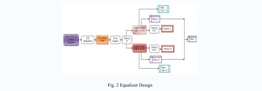
The proposed model for the ISI removal in wireless communication is shown in Fig.2. Transmitter section consists of QAM signal generator and interpolation blocks and the receiver section consist of adaptive equalizer and the symbol recovery blocks.
Fig. 2 Equalizer Design
The real and imaginary parts of signal are generated, interpolated and passed through channel. Down sampling of the distorted signal is done to meet the required sampling rate which further reduces the computational complexity.
Filter is a system that performs mathematical operations on a sampled, discrete-time signal to reduce or enhance certain aspects of that signal. Filter coefficients are saved in buffer which is inside the filter block. The internal block diagram of filter is shown in Fig. 3. The weights are updated in this block. It consists of 2 MAC units used to convolve the input samples with stored coefficient, adds them and stored the result in accumulator. Half of the coefficients are processed by MAC1 and half of coefficients are processed by MAC2. So in this way parallel MAC units can be used to make the operation fast which further enhances the speed of the proposed model.
Fig. 3 Filter
It means symmetric approach is used which is useful for coefficient update of least mean squares (LMSs) and coefficient update of equalizers. Down sampling is also done before samples are passed to MAC which further reduces the number of coefficients to be processed by MAC units. Then filtered signal is passed to symbol recovery block through port 1 and 2, to get the original output. The discrete pulse generator is used to generate regular pulses & at each pulse, the coefficients are passed to buffer from multiport switch. These filter coefficients are scene on the filter tap scope through port3 as shown in Fig. 3. Symbol recovery block recovers the original data.
The coming signal is compared with threshold value, so relational block is used for this purpose. The slicer block is used to extract a given range of bits from each input sample and present it at the output, so specific bits can easily be compared with threshold values.
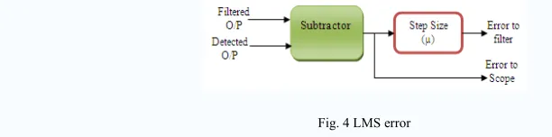
In LMS error calculation block, the filtered signal and the desired signal are compared by subtraction block and then the error is generated which is firstly multiplied with step size value. Then this output is fed back to filter by the ports 1 and 2 and then accordingly filter coefficients are changed to minimize the error. The error produced can also be checked on the scope through the port 3. The internal architecture of LMS error calculation block is shown in Fig. 4.
Fig. 4 LMS error
The process of filtering and updating of filter coefficients is repeated until the error is small enough to get the desired output.
4. Results and Discussions
pronounced during the starting iterations and the effect goes on decreasing with the successive numbers of iterations.
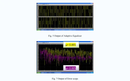
Fig. 5 Output of Adaptive Equalizer
Fig. 7 Output of Error scope
The filtered output has been compared with desired signal to get error signal which is shown in Fig. 7. Here it can be observed that with the numbers of the iterations error reduced to zero. The value of the error for equalizer with step size of 0.005 is -22.68 dB, and the value of error for equalizer with step size of 0.001 is -11.79 dB.
Fig. 8 Filter taps for step size 0.005
The proposed equalizer with step size of 0.005 has been implemented using 104 coefficients which are shown in Fig. 8. Whereas the equalizer with step size of 0.001 has been implemented using 123 coefficients which is shown in Fig. 9.
Fig. 9 Filter taps for step size 0.001 µ= 0.001
Mean Square Error is one of the most important measure of how well an equalizer works. Minimizing the MSE tends to reduce the bit error rate. The table given below shows the MSE of equalizer with different step sizes. MSE with step size of 0.001 is having highest value and the MSE with step size of 0.005 is having lowest value. The range of µ where the constellation diagram is stable is 0.003 to 0.009.
TABLE I COMPARISON of MSE
Step Size MSE in dB 0.001 -11.79 0.002 -9.02 0.003 -22.38 0.004 -22.15 0.005 -22.68 0.006 -20.28 0.007 -19.89 0.008 -18.98 0.009 -19.5
For checking out the best result are coming out from the proposed model, the stability of the constellation diagram can be seen. The constellation diagram of the input QAM signal is shown in Fig. 10.
Fig. 10 Input Constellation diagram
It shows that it has four phases and four amplitudes as in 16 QAM signal. When the signal is passed through the channel it suffers from ISI, then for this the constellation diagram is not stable. That constellation diagram is shown in Fig. 11.
Fig. 11 ISI suffered Constellation Diagram
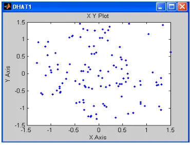
Fig. 12 Constellation diagram for step size 0.005
Here it is observed that with the number of iterations constellation diagram is stabled. But the same diagram with step size of 0.001 is not stable as the number of iterations goes on as shown in Fig. 13.
Fig. 13 Constellation diagram for step size 0.001
Then the VHDL code has been developed and simulated using Modelsim where output is shown in Fig. 14. It can be observed from the modelsim output that the input latency of the proposed equalizer is 7. After the 7th clock period ends, the next cycle begins at once. The real and imaginary inputs and outputs are shown in the Fig. 14.
Fig. 14 Simulation Result of FPGA based LMS algorithm
TABLE II
HARDWARE UTILIZATION REPORT
Logic utilization Used Available Utilization
No of Slices 1349 13696 9% No of Slice FF 1836 27392 6%
No of LUTs 1676 27392 6%
No of IOBs 45 556 8%
No of MULT 16 136 17%
No of GCLK 1 16 6%
Total Power 0.095W
It can be seen from Fig.15 that the proposed design uses very less number of available resources of target device.
Fig. 15 Resource Utilization
The maximum frequency required for the complete process is 121.958MHz. The required minimum input arrival time before clock is1.418ns and the maximum output required time after clock is 3.375ns.
TABLE III COMPARISON REPORT
Logic utilization
Proposed design
Equalizer design [3] CLK Cycles
(Speed factor)
7 12
No of Multipliers / DSP Blocks (Area & cost factor)
16 Mult 18 (DSP
Blocks)
The speed, area and cost utilization of the proposed design has been compared with the equalizer design of [3] which is shown in Table III. It can be observed that the proposed design has the input latency of 7 clocks using 16 multipliers compared to the input latency of 12 using 18 DSP blocks in case of [3]. The proposed design has shown an improvement of 41.7% in speed. Moreover proposed design has been implemented on multipliers based lower end FPGAs in order to provide cost effective solution.
5. Conclusion
equalizer has been designed and implemented on Virtex2 based xc2vp30-7ff896 target device. This proposed equalizer has been developed using symmetric approach to reduce the computational complexity. The partially serial MAC based approach has been used to optimize both speed and area. The proposed design has shown an improvement of 41.7% in speed. This design is implemented on FPGA with embedded multipliers which are less costly than the FPGA with DSP blocks. So, the proposed model can be used to provide speed, area & cost efficient solution for ISI removal in wireless applications.
Acknowledgements
The authors would also like to express his sincere thank and deep sense of gratitude to Dr. S. Chatterji, Professor and Head, Electronics & Communication Department for his constant inspirations, support and helpful suggestions throughout this research work.
References
[1] Ab-Rahman, A.A.H.; Kamisian, I.; Sha'ameri, A.Z.; “VLSI design and implementation of adaptive channel equalizer” Computer and Communication Engineering, 2008. ICCCE 2008. International Conference on 13-15 May 2008 Page(s):1121 – 1124.
[2] Zhifei Fan; Scharf, L.L.; Gubner, J.A.; “Analog Precoder and Equalizer Designs and their Geometry for Multichannel Communication” Wireless Communications, IEEE Transactions on Volume 7, Issue 8, August 2008 Page(s):2957 – 2963.
[3] Guo Yecai; He Longqing; Zhang Yanping; “Design and Implementation of Adaptive Equalizer Based On FPGA” Electronic Measurement and Instruments, 2007. ICEMI '07. 8th International Conference on Aug. 16 2007-July 18 2007 Page(s):4-790-4-794. [4] Wei Zhang; Xiaoli Ma; Gestner, B.; Anderson, D.; ““Designing low-complexity equalizers for wireless systems” Communications
Magazine, IEEE Volume 47, Issue 1, January 2009 Page(s):56 – 62.
[5] Banovic, K.; Khalid, M.A.S.; Abdel-Raheem, E, “FPGA Implementation of a configurable complex blind Adaptive Equalizer”, Signal Processing and Information Technology, 2007 IEEE International Symposium on 2007 , Page(s): 150 – 153
[6] Wireless communication THEODORE S. RAPPAPORT, Page(s): 355-362, 374-376,380
Authors
Chanpreet kaur: Miss Chanpreet kaur is currently pursuing M.E. degree from National Institute of Technical Teachers’ Training and Research, Chandigarh, India. She has completed B.Tech degree in Electronics and Communication from PTU, Jalandhar, Punjab, in 2007. Miss Chanpreet Kaur has authored a paper in National and International Conference. Miss Chanpreet’s interest areas are VLSI Design and Embedded System Design.