Optimization of Radiation Patterns From Isotropic
and Dipole Thinned Arrays
1
D.RamaDevi,
2Dr. G.S.N.Raju
1Dept. of ECE, MVGR College of Engineering, Vizianagaram, Andhra Pradesh, INDIA 2Dept. of ECE, Andhra University, Visakhapatnam, Andhra Pradesh, INDIA
Abstract
A thinned array is represented by a string of binary numbers. Each bit represent the element state either on state i.e. “1” or off state i.e. “0” For example an eight element array may be represented by 10110101,where the elements 2,5,7 are turned off and the elements 1,3,4,6,8 are turned on. Thinning an array to produce low side lobes is much simpler than the more general problem of non uniform spacing of the elements. The control of side lobes using non uniform technique is complex compared with thinning technique. If the array is symmetric then the number of possibilities is substantially smaller. Thinning may be considered as quantized amplitude taper where the amplitude at each element is represented by one bit. The main aim of this work is to find the best thinned array layouts using GA optimization technique with non uniform spacing. The work is extended to array of practical elements using dipole. By using pattern multiplication concept the results were obtained for array of dipoles using optimization technique. The results are very useful for practical applications. From the results it is observed that the first side lobe level and the last side lobe level and nulls are well controlled using this proposed method.
Keywords
GA, Thinning, Dipoles, Isotropic Elements
I. Introduction
Most of the work in literature focused on optimization of amplitude coefficients for fixed beam width to side lobe level ratio. But in this work both amplitude and spacing optimization is considered for fixed beam width to side lobe level ratio .These results are very useful for point to point communication and EMI problems. The work can be extended for other optimization techniques using the same concept. Here the results are compared for array of dipoles and isotropic elements with and without optimization technique. And also optimization technic is compared for isotropic and dipole elements.
A new technique for the design of a thinned, linear, multiplicative array which directly measures the principal solution of a radio
source distribution is described by Macphie [1]. The original
filled multiplicative array with uniform element spacing is first generalized to an array of 1+1subarrays each with 1+1elements. A thinning factor of 1/2 is shown to be possible if 1=1. Finally, if each sub array is further divided into smaller sub arrays until the smallest are simple two element interferometers, then the principal solution can be directly measured but with far fewer elements. Significant thinning factors are achieved when the array is very large. The method can also be used to measure the principal solution with planar arrays with very strong thinning occurring for large arrays.
Haupt [2] presented three approaches to improve the efficiency of an array aperture by interleaving two arrays in the same aperture area. The interleaved arrays have a periodic spacing’s that are integer multiples of a set minimum spacing and are optimized to reduce the maximum side lobe level. Fully and partially interleaved
sum arrays operating at the same frequencies are demonstrated as well as interleaved sum and difference arrays for a mono pulse system. A genetic algorithm is used to optimize arrays of isotropic point sources as well as arrays of dipoles modeled using the method of moments. Narrow beam widths are possible while avoiding high side lobes. The available aperture area is efficiently used.
Hebib et.al [3] focused on the design of thinned planar arrays achieving simultaneously the two following requirements 1) a given beam width in the broadside direction and 2) a given peak side-lobe level in a specified sub-domain of the visible region. It is seen that Cantor spiral arrays are excellent candidates. Peak side lobes of the order of 20 dB and a beam width of 0.6 are obtained with only 200 radiating elements.
Gardeli et.al [4] have proposed a Fabry–Perot cavity (FPC) between a ground plane and a partially reflective surface (PRS) is used here to design array antennas with large distance between the radiating elements. This configuration provides some advantages: i) a reduction of the number of array elements to achieve high directivity; ii) large space between contiguous elements that may host a bulky feeding network as required for dual polarization or active antennas; iii)small coupling and easy feeding network designs because of the smaller number of elements with larger inter-element distance. The presented dual polarized antenna comprises two interleaved 2 arrays placed in a 2-layer FPC, and exhibits a 19 dB gain and 30 dB of isolation between the two ports over an operating bandwidth of approximately 5.7%, i.e., typical for patch antennas.
A new approach for the synthesis of thinned uniformly spaced linear arrays featuring a minimum side lobe level is presented by
Keizer [5]. The method is based on the iterative Fourier technique to derive element excitations from the prescribed array factor using successive forward and backward Fourier transforms. Array thinning is accomplished by setting the amplitudes of the largest element excitations to unity and the others to zero during each iteration cycle. The number of turned ON elements depends on the array filling factor and the total count of element positions. The design of thinned planar micro strip arrays under specific constraints concerning the impedance-matching condition of the array elements and the radiation pattern is presented by Deligkaris et.al [6]. The radiation characteristics of the structure are extracted by applying the method-of-moments. The array design is based on a novel optimization method, which is a modified version of the Boolean particle swarm optimization that employs velocity mutation (BPSO-vm). Apart from the optimization of the array geometry, the proposed method is applicable to the discrete-variable optimization problems.
69
the same method successfully applied earlier to the thinning ofperiodic linear arrays. The effectiveness of the iterative Fourier technique for thinning periodic planar arrays is demonstrated for a number of large arrays (1500 element positions) with a circular aperture using various degree of thinning.
Oliveri et.al [8] proposed an analytical technique based on Almost Difference Sets (ADSs) for thinning planar arrays with well controlled side lobes. The method allows one to synthesize bi dimensional arrangements with Peak Side Lobe Levels (PSLs) predictable and deducible from the knowledge of the array aperture, the filling factor, and the autocorrelation function of the ADS at hand. The numerical validation, concerned with both small and very large apertures, points out that the expected PSL values are significantly below those of random arrays and comparable with those from Different Sets (DSs) although obtainable in a wider range of configurations.
Petko and Werner [9] proposed a multi-objective Pareto genetic algorithm design methodology which is applied to thinned planar arrays to simultaneously minimize peak side-lobe levels and target an elliptical main beam with specific minimum and maximum half-power beam widths. This new radiation pattern synthesis technique for thinned planar arrays provides antenna engineers with a set of tradeoffs between low side-lobe levels and close adherence to main beam design objectives (i.e., the specified half-power beam widths corresponding to the major and minor axes of an elliptical main beam).
A deterministic approach for the design of thinned arrays is
numerically assessed by Rocca [10] when dealing with extremely
large apertures. The method exploits the features of analytical binary sequences with known autocorrelation properties called Almost Difference Sets (ADSs) to efficiently synthesize arbitrary-sized thinned layouts. Performances and computational issues of the ADS technique are analyzed also in the presence of mutual coupling effects and compared to those of a state-of-the-art stochastic optimization method. The results show that the analytical thinning is far more numerically efficient for large layouts than the optimization approach despite a similar side lobe control.
Haupt et.al [11] presented a technique for dynamically altering the thinning configuration of a linear array in order place low side lobe and nulls in desired directions. Interference suppression in uniform linear arrays was attained using this technique.
Lin et.al [12] proposed an antenna array synthesis technique based on simultaneous perturbation stochastic approximation (SPSA) for sparse linear arrays with multiple constraints. The constraints include the number of elements, the array aperture, and the minimum and the maximum distance between two adjacent elements. With a novel vector mapping between the element spacing’s and the variables of SPSA, the constrained optimization problem is simply transformed to a non-constrained optimization problem, and the infeasible solutions are naturally avoided. A novel procedure to thin an antenna array which synthesizes a desired pattern with the minimum number of active elements is
proposed by Corcoles and Gonzalez [13]. The proposed method
yields both the active elements and their corresponding excitations of a thinned array having the minimum number of active elements needed to meet several prescribed design specifications of the radiated far field pattern. Specifications such as achieving a minimum gain, obtaining a pattern with a maximum allowable side lobe level or synthesizing a shaped beam pattern confined into a mask are considered. In order to carry out the thinning, a genetic algorithm is used, while computing the excitations is carried out through linear or quadratic programming. The procedure
incorporates the generalized scattering matrix analysis of an array made up of elements whose radiated field can be expressed as a spherical mode expansion, thus taking all electromagnetic effects inherently into account.
Dealing with the adaptive nulling of the array radiation pattern, two reconfigurable thinning strategies are presented by Poli et.al
[14] and assessed. An easily reconfigurable and low-complexity
antenna architecture is considered where a set of radio frequency switches is exploited to either connect or disconnect the array elements for controlling the radiation pattern and generating deep nulls along the directions-of-arrival of the undesired signals. By defining through a genetic algorithm-based optimization the on/ off status of the switches to maximize the signal-to-interference plus noise ratio at the antenna output, two different formulations are discussed. The first one does not constrain the number of active elements, while the other forces the solution to satisfy a fixed-directivity criterion also in correspondence with a time-varying interference scenario. The performances of the proposed approaches are assessed in both static and time-varying scenarios where single and multiple interfering signals impinge on the array from different angular directions.
Considering the synthesis of interleaved antenna arrays with shared and inactive elements a hybrid Genetic Algorithm (GA) where the initial population is seeded with good solutions is proposed by Plessis and Ghannam [15]. A number of seeding schemes are considered and the most effective of these are identified. The proposed algorithm is shown to reliably produce results with Side Lobe Level (SLL) values which are close to the optimum and to converge faster than the other algorithms considered. However, some of the seeding schemes mislead the GA and actually produce worse results than random initialization.
II. Formulation
The radiation characteristics can be obtained using the concept of vector magnetic potential. In the present work a horizontal dipole is considered and expressions for magnetic potential is formulated. The vector magnetic potential [16] of a dipole of a specified length is evaluated by considering a differential current element on the dipole. A differential current element results in a differential vector magnetic potential. The total potential is obtained by integrating the differential potential over its length.
The magnetic field is found out from the knowledge of the potential
from the expression Consider a thin wire antenna
located in free space. To obtain far-field pattern, the distance r
should be much greater than wavelength.
Let E be the electric field and r is the radius vector. Then the electric field is in the form of
(1) A(r) is the vector magnetic potential at point ‘r’ .
Here, ar is the unit vector from the origin towards the point of
interest.
The computed magnetic field vector is given by
(2)
current in the wire can be assumed to be along its axis.
As a result, the vector magnetic potential in the far-field zone is approximately written in the form of
(3)
Here, G(r) is Green’s function
axm is unit vector tangential to wire axis
r is the distance from origin to element dXm
N is number of segments If the wire segments are straight
(4)
From the above equations, Electric field is given by
(5)
Here, aө and aø are the unit vectors of the spherical coordinate system.
N m
X I X
I im
n
i m m
m
m
i , ,12,...
) (
0
, =
∑
==
(6)
Here, nm is the desired degree of polynomial.
From the derived current distribution the current field strength can be shown as
(7)
Im is current maximum
Further it can be simplified into the following form.
The electric field in the far field region in free space is determined using the relation between E and H. As the element of interest is horizontal, assuming sinusoidal current distribution in the element the field strength as a function of Sinθ is given by
(8)
l is length of the dipole
The radiation pattern of array of any given antenna can be obtained from the following equation.
(9)
Where F(θ) is the element pattern of the antenna under
consideration
Practical schemes used in GA:
Here Binary GA has been used [17].
Binary GA
In rank selection, the individuals are sorted by fitness. The probability that individual is selected is then inversely proportional to its position in this sorted list, i.e. the individual at the head of
the list is more likely to be selected than the next individual, and so on through the sorted list.
Offspring can be generated from selected parents in a number of different ways. For binary chromosomes, uniform crossover is the most general procedure. A mask that consists of ones and zeros is generated for each set of parents. The mask has the same number of bits as the parent chromosomes.
Uniform crossover:
Mask=round(rand(1,nvar*nbit))
offspring1=mask.*mother+not(mask).*father offspring2=not(mask).*mother+mask.*father
For the binary GA, mutation rateamounted to just changing a bit from a 0 to a 1, and vice versa.
pop (mutindx)=abs(pop(mutindx)-1)
Algorithm for Binary GA
Step 1: Define cost function,cost,variables and select GA parameters
Step 2: Generate initial population Step 3: Decode chromosomes
Step 4: Find cost for each chromosome Step 5: Select mates
Step 6: Mating Step 7: Mutation
Step 8: Convergence Check Step 9: Done else Go to step 3
The fitness function associated with this array is the maximum Side Lobe Level of its associated radiation field pattern to be minimized. The general form of the fitness function is given by [14].
(10)
Max |E (θ0)|=|E (θ)| -π/2 ≤ θ ≤ π/2, θ ≠ 00
III. Results
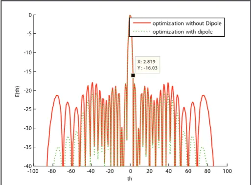
For isotropic element and dipole array using thinning
-100 -80 -60 -40 -20 0 20 40 60 80 100 -40
-35 -30 -25 -20 -15 -10 -5 0
X: 2.819 Y : -16.03
th
E(th)
optimization without Dipole optimization with dipole
71
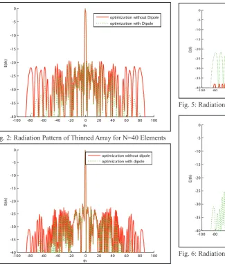
-100 -80 -60 -40 -20 0 20 40 60 80 100 -40
-35 -30 -25 -20 -15 -10 -5 0
th
E(th)
optimization without Dipole optimization with Dipole
Fig. 2: Radiation Pattern of Thinned Array for N=40 Elements
-100 -80 -60 -40 -20 0 20 40 60 80 100 -40
-35 -30 -25 -20 -15 -10 -5 0
th
E(th)
optimization without dipole optimization with dipole
Fig. 3: Radiation Pattern of Thinned Array for N=60 Elements
Table 1: Comparison of Beam Widths and Side Lobe Levels for Isotropic Element and Dipole Using Thinning
No. of Elements
Dipole Elements Isotropic Elements
Max SLL
(dB) B.W (Deg) Max SLL (dB) B.W (Deg)
20 -18.3 5.638 -17.98 5.638
40 -19.94 3.528 -19.41 3.528
60 -21.16 2.384 -22.67 2.384
For isotropic element using with and without thinning
-100 -80 -60 -40 -20 0 20 40 60 80 100 -40
-35 -30 -25 -20 -15 -10 -5 0
th
E(th)
is otropic without G A is otropic with G A
Fig. 4: Radiation Pattern of Isotropic Array for N=20 Elements
-100 -80 -60 -40 -20 0 20 40 60 80 100
-40 -35 -30 -25 -20 -15 -10 -5 0
th
E(th)
is otropic without G A is otropic with G A
Fig. 5: Radiation Pattern of Isotropic Array for N=40 Elements
-100 -80 -60 -40 -20 0 20 40 60 80 100 -40
-35 -30 -25 -20 -15 -10 -5 0
th
E(th)
is otropic with out G A is otropic with G A
Fig. 6: Radiation Pattern of Isotropic Array for N=60 Elements
Table 2: Comparison of Beam Widths and Side Lobe Levels for Isotropic Elements With and Without GA
No.of Elements
Isotropic Elements
with GA Isotropic Elementswithout GA
Max
SLL(dB) B.W (Deg) Max SLL (dB) B.W (Deg)
20 -18.06 5.592 -13.5 5.592
40 -19.41 3.528 -13.5 3.528
60 -21.13 3.346 -13.5 3.346
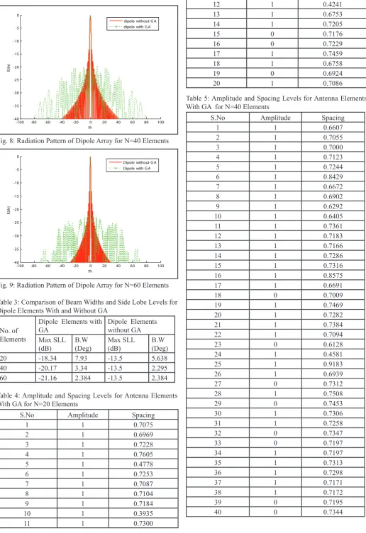
For Dipole elements using with and without thinning
-100 -80 -60 -40 -20 0 20 40 60 80 100
-40 -35 -30 -25 -20 -15 -10 -5 0
th
E(th)
dipole without thinning dipole with thinning
-100 -80 -60 -40 -20 0 20 40 60 80 100 -40
-35 -30 -25 -20 -15 -10 -5 0
th
E(th)
dipole without G A dipole with G A
Fig. 8: Radiation Pattern of Dipole Array for N=40 Elements
-100 -80 -60 -40 -20 0 20 40 60 80 100 -40
-35 -30 -25 -20 -15 -10 -5 0
th
E(th)
Dipole without G A Dipole with G A
Fig. 9: Radiation Pattern of Dipole Array for N=60 Elements
Table 3: Comparison of Beam Widths and Side Lobe Levels for Dipole Elements With and Without GA
No. of Elements
Dipole Elements with
GA Dipole Elements without GA
Max SLL
(dB) B.W (Deg) Max SLL (dB) B.W (Deg)
20 -18.34 7.93 -13.5 5.638
40 -20.17 3.34 -13.5 2.295
60 -21.16 2.384 -13.5 2.384
Table 4: Amplitude and Spacing Levels for Antenna Elements With GA for N=20 Elements
S.No Amplitude Spacing
1 1 0.7075
2 1 0.6969
3 1 0.7228
4 1 0.7605
5 1 0.4778
6 1 0.7253
7 1 0.7087
8 1 0.7104
9 1 0.7184
10 1 0.3935
11 1 0.7300
12 1 0.4241
13 1 0.6753
14 1 0.7205
15 0 0.7176
16 0 0.7229
17 1 0.7459
18 1 0.6758
19 0 0.6924
20 1 0.7086
Table 5: Amplitude and Spacing Levels for Antenna Elements With GA for N=40 Elements
S.No Amplitude Spacing
1 1 0.6607
2 1 0.7055
3 1 0.7000
4 1 0.7123
5 1 0.7244
6 1 0.8429
7 1 0.6672
8 1 0.6902
9 1 0.6292
10 1 0.6405
11 1 0.7361
12 1 0.7183
13 1 0.7166
14 1 0.7286
15 1 0.7316
16 1 0.8575
17 1 0.6691
18 0 0.7009
19 1 0.7469
20 1 0.7282
21 1 0.7384
22 1 0.7094
23 0 0.6128
24 1 0.4581
25 1 0.9183
26 1 0.6939
27 0 0.7312
28 1 0.7508
29 0 0.7453
30 1 0.7306
31 1 0.7258
32 0 0.7347
33 0 0.7197
34 1 0.7197
35 1 0.7313
36 1 0.7298
37 1 0.7171
38 1 0.7172
39 0 0.7195
73
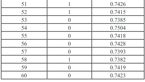
Table 6: Amplitude and Spacing Levels for Antenna ElementsWith GA for N=60 Elements
S.No Amplitude Spacing
1 1 0.7405
2 1 0.7422
3 1 0.7403
4 1 0.7392
5 1 0.7440
6 1 0.7401
7 1 0.7410
8 1 0.7439
9 1 0.7439
10 1 0.5298
11 1 0.8351
12 1 0.7449
13 1 0.7409
14 1 0.7412
15 1 0.7434
16 1 0.7389
17 1 0.7445
18 0 0.7371
19 1 0.7427
20 1 0.7407
21 1 0.7410
22 1 0.7381
23 1 0.7360
24 1 0.7468
25 1 0.7455
26 1 0.7516
27 0 0.7421
28 1 0.7409
29 1 0.7456
30 0 0.5031
31 1 0.5462
32 1 0.7436
33 1 0.5213
34 0 0.7404
35 1 0.7419
36 0 0.7414
37 1 0.7420
38 1 0.7343
39 0 0.7456
40 1 0.7438
41 0 0.7401
42 1 0.7407
43 1 0.7408
44 1 0.7465
45 1 0.7419
46 1 0.7440
47 1 0.6739
48 1 0.7434
49 0 0.7379
50 1 0.5348
51 1 0.7426
52 1 0.7415
53 0 0.7385
54 0 0.7504
55 0 0.7418
56 0 0.7428
57 0 0.7393
58 1 0.7382
59 0 0.7419
60 0 0.7423
IV. Conclusions
In this paper array thinning is considered for different array lengths with 0.5 lamda spacing. The SLL is well controlled and the null to null beamwidth points are achieved to the desired level. However, thinning is considered for array of dipoles and array of isotropic elements which are mostly used for practical applications. Here both beamwidth and sll are well controlled using amplitude and spacing optimization. From the results it is observed that for N=20 the SLL is -18dB and for N=40 it is -19dB and for N=60 it is -21dB. As the number of elements increases beamwidth decreases. These type of patterns are very useful for point to point communications with digital phase shifters and array beam forming is achieved.
References
[1] Robert H. MacPhie,“Thinned Coincident Arrays for the Direct Measurement of the Principal Solution in Radio Astronomy”, IEEE Transactions On Antennas And Propagation., Vol. 51, No. 4, pp. 783-793, April 2003.
[2] Randy L. Haupt,“Interleaved Thinned Linear Arrays”, IEEE Transactions on Antennas and Propagation., Vol. 53, No. 9, pp. 2858-2864, Sept. 2005.
[3] S. Hebib, N. Raveu, H. Aubert,“Cantor Spiral Array for the Design of Thinned Arrays”, IEEE Antennas And Wireless Propagation Letters., Vol. 5, pp. 104-106, May 2006. [4] Renato Gardelli, MatteoAlbani, Filippo Capolino,“Array
Thinning by Using Antennas in a Fabry–Perot Cavity for Gain Enhancement”, IEEE Transactions on Antennas and Propagation, Vol. 54, No. 7, pp. 1979-1990, July 2006. [5] Will P. M. N. Keizer,“Linear Array Thinning Using Iterative
FFT Techniques”, IEEE Transactions On Antennas And Propagation., Vol. 56, No. 8, pp. 2757-2760, Aug. 2008. [6] Kosmas V. Deligkaris, Zaharias D. Zaharis, Dimitra G.
Kampitaki, Sotirios K. Goudos, Ioannis T. Rekanos, Michalis N. Spasos,“Thinned Planar Array Design Using Boolean PSO With Velocity Mutation”, IEEE Transactions On Magnetics., Vol. 45, No. 3, pp. 1490-1493, March 2009.
[7] Will P. M. N. Keizer,“Large Planar Array Thinning Using Iterative FFT Techniques”, IEEE Transactions On Antennas And Propagation., Vol. 57, No. 10, pp. 3359-3362, Oct. 2009.
[8] Giacomo Oliveri, Luca Manicaand Andrea Massa,“ADS-Based Guidelines for Thinned Planar Arrays”, IEEE Transactions on Antennas and Propagation., Vol. 58, No. 6, pp. 1935-1948, June 2010.
[10] P. Rocca,“Large Array Thinning by Means of Deterministic Binary Sequences”, IEEE Antennas And Wireless Propagation Letters., Vol. 10, pp. 334-337, Oct. 2011.
[11] Paolo Rocca, Randy L. Hauptand Andrea Massa, “Interference Suppression in Uniform Linear Arrays Through a Dynamic Thinning Strategy”, IEEE Transactions On Antennas And Propagation., Vol. 59, No. 12, pp. 4525-4533, Dec. 2011. [12] Zhiqiang Lin, WeiminJia, Minli Yao, LuyaoHao, “Synthesis
of Sparse Linear Arrays Using Vector Mapping and Simultaneous Perturbation Stochastic Approximation”, IEEE Antennas and Wireless Propagation Letters., Vol. 11, pp. 220-223, Nov. 2012.
[13] Juan Córcoles, Miguel A. González,“Efficient Combined Array Thinning and Weighting for Pattern Synthesis Witha Nested Optimization Scheme”, IEEE Transactions on Antennas and Propagation., Vol. 60, No. 11, pp. 5107-5117, Nov. 2012.
[14] Lorenzo Poli, Paolo Rocca, Marco Salucci, Andrea Massa, “Reconfigurable Thinning for the Adaptive Control of Linear Arrays”, IEEE Transactions on Antennas and Propagation, Vol. 61, No. 10, pp. 5068-5079, Oct. 2013.
[15] W. P. du Plessis, A. bin Ghannam,“Improved Seeding Schemes for Interleaved Thinned Array Synthesis”, IEEE Transactions on Antennas And Propagation., Vol. 62, No. 11, pp. 5906-5910, Nov. 2014.
[16] Kesong Chen, Zishu He, Chunlin Han,“A Modified Real GA for the Sparse Linear Array Synthesis with Multiple Constraints”, IEEE Transactions on Antennas and Propagation, Vol. 54, No. 7, pp. 2169-2173, 2006.
[17] Randy L. Haupt,“An Introduction to Genetic Algorithms for Electromagnetics”, IEEE Antennas Author’s Information.
Dr. G.S.N. Raju received his B.E., M.E. with distinction and first rank from Andhra University and Ph.D. from IIT, Kharagpur. He is presently Vice-Chancellor, Andhra University, Visakhapatnam, India. He is in teaching and research for the last 30 years in Andhra University. He guided 29 Ph.D.s in the fields of Antennas, Electro Magnetics, EMI/EMC and Microwave, Radar Communications, Electronic circuits. Published about 300 technical papers in National/International Journals/Conference Journals and transactions. He is the recipient of The State Best Teacher Award‟ from the Government of Andhra Pradesh in 1999, ‟The Best Researcher Award‟ in 1994, ‟Prof. Aiya Memorial National IETE Award‟ for his best Research guidance in 2008 and Dr. Sarvepalli Radhakrishnan Award for the Best Academician of the year 2007, He was a visiting Professor in the University of Paderborn and also in the University Karlsruhe, Germany in 1994. At present he holds the positions of Vice-Chancellor, Andhra University, Visakhapatnam. He was Chief Editor of National Journal of Electromagnetic Compatibility. Prof. Raju has published five textbooks Antennas and Wave Propagation, Electromagnetic Field Theory and Transmission Lines, Electronics Devices and Circuits, Microwave Engineering, Radar Engineering and Navigational Aids. Prof. Raju has been the best faculty performer in Andhra University with the performance index of 99.37.