SLEEP & WAKEUP TECHNIQUE BASED CLUSTERING
PROTOCOL-PERFORMANCE EVALUATION IN WIRELESS
SENSOR NETWORK
1Dr.M.SENTHIL, 1Dr.P.SIVAKUMAR, 2T.C.INDHUMATHI
1
Professor, Department of Electronics and Communication Engineering, SKP Engineering College, Tiruvannamalai.
2
PG-Scholar., Department of Embedded system Technologies, SKP Engineering College, Tiruvannamalai. E-mail: [email protected], [email protected]
ABSTRACT
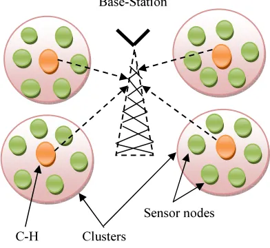
In order to achieve data information, the Sensor Node’s should form into small groups as clusters in wireless sensor network. In Multi-hop sensor network, the Base-Station (sink) is might not be considered. That is why, the hot-spot problem may occur in this network. In this paper, we analyze the sleep & wakeup approach, in order to avoid the hot spot (WLAN) problem, which aims to increase the network lifetime using energy conservation as well as increasing packet delivery ratio (PDR). In this technique, C-H (cluster-head) has been selected based on energy level & Base-Station distance. Using this technique, we can improve the energy conservation & PDR up to 63%, when compare to that of FCA (fuzzy clustering algorithm) according to their parameters of FND (First Node Dead) and HNA (Half of the Node Alive) parameter for each algorithm. Our simulation results shows that the sleep & wakeup approach is better and energy efficient clustering protocol based on their parameters.
Keywords: WSN; clustering; FCA; Sleep & Wakeup Technique.
1.
INTRODUCTIONWireless Sensor Network [1] performs “wireless communication” based on battery powered sensor nodes. The sensor nodes can sense the data information and send it to their base-station. After replacing (or) recharging the battery power level of each sensor nodes are not possible, when the battery power is low. The homogeneous and heterogeneous sensor nodes have chosen based on amount of energy level having same energy level; it is homogeneous, If not heterogeneous sensor node. WSN have used in many applications ex: Military applications for battlefield surveillance, Habitat monitoring, Disaster relief, Target tracking etc…
In WSN, each sensor nodes can aggregate all the clustering information known as data aggregation, which gives accurate results. Then they are partition in to small groups like clusters [2], [4]. Each cluster has a head known as C-H. Finally the packet transmission will taken place in between C-H as well as Base-Station. In this, each sensor node have a Digital Signature ID to send the data information to Base-Station in order to avoid the DoS attack, which means the sensor (source) node can send the data information with digital signature ID to Base- station. This can sense the information with digital
signature ID, and then it can receive the data information. Figure 1 shows the WSN architecture.
Base-Station
[image:1.595.323.519.474.654.2]Sensor nodes C-H Clusters
Figure 1: Wsn Architecture
573 Vaibhav Godbole [9] proposed this has protocol has used threshold value for selecting temporary C-H between 0’s and 1’s in competitive manner. From these temporary C-H’s, Base-Station can select one static C-H based on their energy as well as Base-station distance. In Fuzzy Clustering Algorithm, fuzzy logic has used to avoid the uncertainties of C-H radius estimation.
In order to improve the energy saving and get a high packet delivery ratio (PDR), we use sleep & wakeup protocol [10] like as routing protocol. In this approach, the path has created in between C-H’s as well as Base-station. If the sensor nodes are in path, then it becomes awaken nodes. Rests of the nodes are sleep nodes. Here, wake up node only can send their data information to base station according to the parameters.
2.
RELATED WORK-CLUSTERINGPROTOCOL
1 Fuzzy Clustering Algorithm
Fuzzy Clustering Algorithm [6] is a distributed competitive Algorithm. The temporary cluster-head’s has been selected by using threshold value. In every round, the temporary C-H have selected by randomized rotation manner (number between 0&1). From these temporary H, the permanent C-H has been selected by using Mamdani method [7] of fuzzy inference technique have the fuzzy if-then rules with linguistic variables, which means based on the energy consumption and base-station distance the C-H has selected. Figure 2 shows the Fuzzy Clustering Algorithm design.
Cluster Base-station Temporary C-H
Permenant C-H
[image:2.595.311.510.75.274.2]
Sensor Nodes
Figure 2: Fuzzy Clustering Algorithm
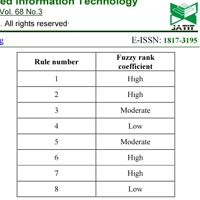
Fuzzy if-then Rules [8] as shown in table 1 was considered as the fuzzy descriptors, they are
(i) Node mobility
(ii) Base-station distance (iii) Energy
(iv) The Centrality of Nodes.
TABLE 1:FUZZY IF-THEN RULES WITH LINGISTIC VARIABLES
Rule number Fuzzy rank
coefficient
1 High
2 High
3 Moderate
4 Low
5 Moderate
6 High
7 High
8 Low
The FCA uses A* Algorithm is used to sense the path and find its destination (Base-Station) as explained below. In fuzzy clustering algorithm, the Base-Station can select new accurate C-Hs based on the energy as well as C-H radius distance, for the reason that, the Base-Station has known about all the clustering information in a network as like Centralized Clustering Algorithm [9]. Followed by the data packet has been send from C-H to Base Station. Assume if any problem occurs in C-H radius estimation, then we must use the fuzzy logic condition in order to solve the problem, since fuzzy logic, put together a real time decisions in a complete network. Algorithm. 1 shows the Fuzzy Clustering Algorithm uses A* algorithm
Algorithm 1: The Fca Uses A* Algorithm
The disadvantage of the FCA is (i) Battery level
of sensor nodes, because the Base-Station has accumulated the C-H in a network. Do again this processes the battery level gets discharge.
1. function A* (start)
2. set clusters
3. set empty set // for temporary C-H
selection.
4. set T(n) µ(0,1)
5. if THRESHOLD T(n) < Number
be Temporary C-H TRUE
6. if THRESHOLD T(n) > Number
be Temporary C-HFALSE
7. end if
8. end if
9. apply fuzzy if- then rules = avoid uncertainties
10. Rcompetition & Energy for C-H selection
11. if sensor node high energy &< Rcomp
distance.
12. be static C-H TRUE
13. else
14. static C-H FALSE
15. end if
[image:2.595.85.303.508.653.2](ii) Also in FCA, all the sensor nodes are in active sensor nodes. So it can spent more energy to propagate and send the data packet information to Base-Station.
2 Sleep and Wakeup Approach
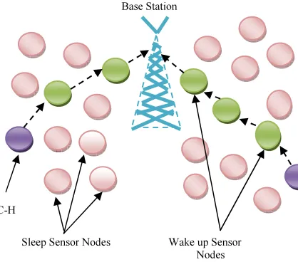
In sleep and wakeup approach [12], aims to increase the WSN lifetime by using reducing the energy consumption as well as increasing the Packet Delivery Ratio (PDR). Yan Wu et al., [10] proposed this approach is routing algorithm. The C-H has selected based on energy efficiency [11] and base station distance, subsequently the data packet transmission will takes place. Figure 3 shows the Sleep & Wakeup Technique design.
Base Station
C-H
Sleep Sensor Nodes Wake up Sensor
[image:3.595.90.299.306.490.2]Nodes
Figure 3: Sleep & Wake Up Approach
Algorithm 2, Sleep & Wakeup Approach [14] as explained below. Here the C-H has been selected as a mobile node. In mobility manner, the C-H can create a path to Base-station. Then the Base station can send the WORK_REQUEST message to C-H. If the sensor nodes are in the path, then the C-H can send the WORK message. Consequently, that particular sensor node becomes a wake up node [13]. After that the data packet transmission will taken place to base station. If the nodes are away from the path, then the C-H can send the sleep message. Subsequently, the sleep node does not send the data packet to base station.
After completing the data packet transmission, the sleep nodes preserve the WORK_REQUEST message to C-H, then the C-H can move from one place to another place, and then this process will repeated again, because of high-energy conservation. If any packet loss occurs, then the
packet transmission will stop. Using this packet loss, we have to create a parameter of FND (first node dead) of HNA (half of the node alive) condition. Algorithm 2 shows the Sleep & Wakeup Technique algorithm.
Algorithm 2: The Sleep & Wakeup Technique
.
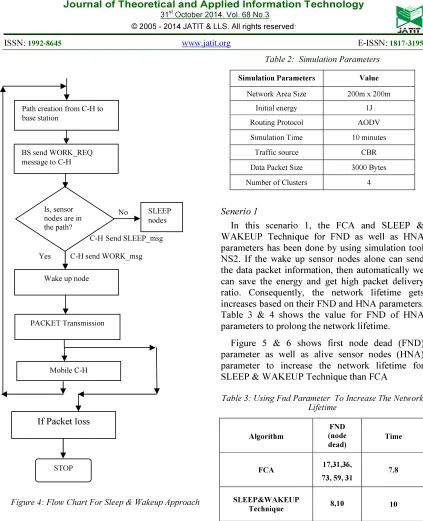
Figure 4 shows the flow chart for Sleep & Wakeup Approach. The flow chart shows,” how the packet will be transmitted” and it becomes dead.
Flowchart:
1. Node state cluster member
2. Rcompetition & Energy for C-H selection
3. if sensor node high energy &< Rcomp distance.
4. be static C-H TRUE
5. else
6. static C-H FALSE
7. end if
8. path creation C-H to basestation
9. if Ready to wake upsensor nodes
10. work_req msg send from C-H to
sensor
node
11. be wake up node = TRUE
12. sleep_msg send from C-H to rest
of the
nodes
13. be sleep node = TRUE
14. if completed packet transmission
15. Mobile C-H Repeats step 8
16. work_req send from sleep nodes to
C-H
17. packet transmission from
C-H to base station
18. end if
19. end if
20. exit
575
No
C-HSend SLEEP_msg
Yes C-H send WORK_msg
[image:4.595.84.507.72.593.2]
Figure 4: Flow Chart For Sleep & Wakeup Approach
3.
SIMULATION RESULTS ANDDISCUSSION
[image:4.595.87.275.106.558.2]In simulation part we just compare and study the performance of the FCA with Sleep & Wake up Technique by using Network Simulator 2.32(NS2) [16] [17]. .Network simulator2 is a powerful tool and it is object oriented. The NAM area size is 200m x 200m. In this, Sleep & Wake up Technique makes a routing path to send the data packet information from source node to destination node. The table 2 represents the simulation parameters.
Table 2: Simulation Parameters
Simulation Parameters Value
Network Area Size 200m x 200m
Initial energy 1J
Routing Protocol AODV
Simulation Time 10 minutes
Traffic source CBR
Data Packet Size 3000 Bytes
Number of Clusters 4
Senerio 1
In this scenario 1, the FCA and SLEEP & WAKEUP Technique for FND as well as HNA parameters has been done by using simulation tool NS2. If the wake up sensor nodes alone can send the data packet information, then automatically we can save the energy and get high packet delivery ratio. Consequently, the network lifetime gets increases based on their FND and HNA parameters. Table 3 & 4 shows the value for FND of HNA parameters to prolong the network lifetime.
[image:4.595.302.511.483.596.2]Figure 5 & 6 shows first node dead (FND) parameter as well as alive sensor nodes (HNA) parameter to increase the network lifetime for SLEEP & WAKEUP Technique than FCA
Table 3: Using Fnd Parameter To Increase The Network Lifetime
Algorithm
FND (node dead)
Time
FCA 17,31,36,
73, 59, 31
7.8
SLEEP&WAKEUP
Technique 8,10 10
Is, sensor nodes are in the path?
SLEEP nodes
PACKET Transmission
STOP Wake up node Path creation from C-H to base station
BS send WORK_REQ message to C-H
Mobile C-H
FIGURE 5:FIRST NODE DEAD (FND)PARAMETER FOR FCA
AND SLEEP&WAKEUP TECHNIQUE
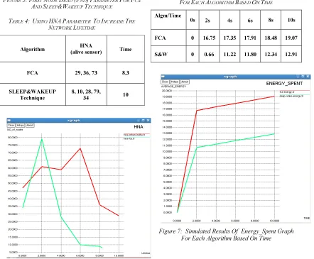
TABLE 4: USING HNAPARAMETER TO INCREASE THE
NETWORK LIFETIME
Algorithm HNA
(alive sensor) Time
FCA 29, 36, 73 8.3
SLEEP&WAKEUP Technique
8, 10, 28, 79,
34 10
Figure 6: Alive Sensor Nodes (Hna) Parameter For Fca And Sleep & Wakeup Technique.
In simulation results, the sleep & wakeup Approach [17], have many sensor nodes in a
network. From these sensor nodes, the C-H has been selected based on their energy as well as base station distance. Consequently, the path [18] has been created from C-H to Base station. If the sensor nodes are in the path, it will become a wake up node has to create a data packet transmission between C-H to BS (base station). Therefore, the energy_spent get decrease and get high PDR in a simulated network algorithm.
Based on time, the energy and PDR value has taken by NS2. In Sleep & Wake up approach, the energy _spent is low as well as the PDR get increase, when compare with FCA. Table 5 & 6 shows the simulation parameter of energy spent & PDR for each algorithm based on time. Figure 7 and 8 shows done the simulation results for energy Spent and PDR.
TABLE 5: SIMULATION PARAMETER ENERGY_SPENT VALUE
FOR EACH ALGORITHM BASED ON TIME
Algm/Time
0s 2s 4s 6s 8s 10s
FCA 0 16.75 17.35 17.91 18.48 19.07
S&W 0 0.66 11.22 11.80 12.34 12.91
[image:5.595.89.289.107.327.2] [image:5.595.88.530.339.704.2]577
Table 6: Simulation Parameter Pdr Value For Each Algorithm Based On Time
Algm/Time
0s 2s 4s 6s 8s 10s
FCA 0
0.42 50
0.45 68
0.47 93
0.542 4
0.607 5
S&W 0 0.72
17 0.76
16 0.86
54 0.892
5
0.938 5
Figure 8: Simulated Results Of Pdr Graph For Each Algorithm Based On Time
4.
CONCLUSIONWe have presented about the FCA as well as Sleep & Wakeup Technique. Under this work, the FCA has high energy spent and low PDR when compare to that of Sleep & Wake up Technique. Here we have increased the energy efficiency and packet delivery ratio (PDR) along with FND of HNA parameters to extend the network lifetime. However, the energy can be saved up to 63% along with PDR when compared to FCA.
As a future work, the Sleep & Wake up Approach can be extended for Mobile Sensor Network (MSN) like all sensor nodes as a mobile.
REFRENCES:
[1] C.Y Chong S.P. Kumar, Sensor networks: evolution, opportunities, and challenges, Proceedings of the IEEE 91 (8) pp. 1247– 1256, 2003.
[2] Siddhartha Chauhan and Lalit Kumar Awasthi, “Cluster Based Task Scheduling in Wireless Sensor Network”, International Journal of
Computer Applications (0975 – 8887) Volume 33 – No.4, November 2011.
[3] J.Yu and P. Chong, "A survey of clustering schemes for mobile ad hoc networks," IEEE Communications Surveys & Tutorials, vol. 7, pp. 32-48, 2005.
[4] E. Heidari, "Intelligent Clustering in Wireless Sensor Networks," in First International Conference on Networks and Communications, 2009. {NETCOM '09}, 2009, pp. 12-17. [5] A.K Jamal N and others,” Routing Techniques
in Wireless Sensor Network- A Survey” IEEE Wireless Communication 2004.
[6] Vaibhav Godbole,” Performance analysis of clustering protocol using fuzzy logic for WSN”,in: IAES International Journal of Artificial Intelligence vol 1, sep2012, pp.103-111.
[7] J.-M. Kim, S.-H. Park, Y.-J. Han, and T.-M. Chung, "CHEF: Cluster Head Election mechanism using Fuzzy logic in Wireless Sensor Networks," in Proc. 10th Int. Conf. Advanced Communication Technology ICACT 2008, vol. 1,2008, pp. 654-659.
[8] Y. Meng and L. for Kwok, "A case study: Intelligent false alarm reduction using fuzzy if-then rules in network intrusion detection," in Proc. 9th Int Fuzzy Systems and Knowledge Discovery (FSKD) Conf, 2012, pp. 505-509. [9] D. R. I. Gupta and S. Sampalli, "Cluster-head
election using fuzzy logic for wireless sensor networks," in 3rd Annual Conference on Communication Networks and Services Research, vol. 2, 2005.
[10]Yan Wu, Sonia Fahmy, Ness B. Shroff “Sleep/Wake Scheduling for Multi-hop Sensor Networks: Non-convexity and Approximation Algorithm”, October 7, 2009
[11]Sha Liu, Kai-Wei Fan, Prasun Sinha “Dynamic Sleep Scheduling using Online Experimentation for Wireless Sensor Networks”, 2005
[12]Bo Jiang, Binoy Ravindran and Hyeonjoong Cho “Energy Efficient Sleep Scheduling in Sensor Networks for Multiple Target Tracking”, 2009.
[14]Guofang Nan, Guanxiong Shi, Zhifei Mao and Minqiang Li “CDSWS: coverage-guaranteed distributed sleep/ wake scheduling for wireless sensor networks”, EURASIP Journal on Wireless Communications and Networking 2012.
[15]Chia Hung Tsai, Yu Chee Tseng, “A path connected-cluster wireless sensor network and its formation, addressing, and routing algorithms”, IEEE Sensors Journal, Volume 12, Number 6, 2012.
[16]Network Simulator:
http://www.isi.edu/nsnam/ns.
[17]M. Greis. Tutorial for the Network Simulator
NS2. [Online]. Available: