Implementation of Convolution Encoder & Viterbi Decoder
Dontabhaktuni Jayakumar
1Rayapati Guruswamy Nikitha
21
Assistant Professor
2B.Tech Student
1,2
Department of Electronic & Communication Engineering
1
Holy Mary Institute of Technology & Science, Bogaram, Hyderabad, India
2GITAM Deemed to be
University, Hyderabad, Telangana, India
Abstract— In the present scenarios, data transferring between the systems plays a vital role as the technologies are increasing day-by-day the number of users is simultaneously increasing. This wide usage leads to major issues in the digital communication systems and results in data corruptions. It’s very necessary for the telecommunication to reduce the data corruption by providing a suitable solution to the errors occurred in the communication process. One such method that decodes the process by simultaneously correcting the process effectively is Viterbi algorithm. For decoding the convolution codes Viterbi algorithm is the highest recognizable algorithm. This algorithm may be described with software as well as hardware implementations. To engage well organized communications an efficient data is presented by the digital systems. Data corruptions are the important issue confronted by the digital communication systems. To decrease data corruptions error correcting codes is a best technique. Al most all communication systems followed it because it’s power to decode efficiently, even Viterbi algorithm needs very typical hardware. While the decoding operation is in advance, the functioning obstructions can be eliminated, So that an improved method, Adaptive Viterbi Algorithm is used. The decoding of codes can be done very fast, as this algorithm is very effective in high speed functions. Convolution codes are used to gain a possible code sequences AVA uses maximum –likelihood decoding process.
Key words: Convolution Encoder, Viterbi Decoder
I. INTRODUCTION
Hardware description language called Verilog HDL is used to valuate this project, where it is one of the hardware descriptive languages that stand for Verilog Hardware Description Language. This language is employed in designing the electronic systems to semiconductor and electronic design industries as well as for assuring the analog and mixed signal circuit. This research makes use of two main tools namely MODELSIM – Simulation and XILINX-ISE – Synthesis for successfully reaching its objectives. Further of this research provides a clear description on Adaptive Viterbi Algorithm, its execution process and various kinds of languages and tools for evaluating the Viterbi Algorithm.
Convolutional coding has been used in communication systems including deep space communications and wireless communications. It offers an alternative to block codes for transmission over a noisy channel. An advantage of convolutional coding is that it can be applied to a continuous data stream as well as to blocks of data. IS-95, a wireless digital cellular standard for CDMA (code division multiple access), employs convolutional coding. A third generation wireless cellular standard, under preparation, plans to adopt turbo coding, which stems from convolutional coding. The Viterbi decoding algorithm,
proposed in 1967 by Viterbi, is a decoding process for convolutional codes in memory-less noise [52].
The algorithm can be applied to a host of problems encountered in the design of communication systems [52]. The Viterbi decoding algorithm provides both a maximum-likelihood and a maximum a posteriori algorithm. A maximum a posteriori algorithm identifies a code word that maximizes the conditional probability of the decoded code word against the received code word, in contrast a maximum likelihood algorithm identifies a code word that maximizes the conditional probability of the received code word against the decoded code word. The two algorithms give the same resultswhen the source information has a uniform distribution.
Traditionally, performance and silicon area are the two most important concerns in VLSI design. Recently, power dissipation has also become an important concern, especially in battery powered applications, such as cellular phones, pagers and laptop computers. Power dissipation can be classified into two categories, static power dissipation and dynamic power dissipation.
A. Aim & Objectives 1) Aim
Execution of Viterbi algorithm applying VHDL coding. 2) Objectives
To clearly understand the Hidden Markov model and Viterbi Decoder.
To evaluate the basic functionalities and steps involved in Viterbi algorithm
To research on the implementation of Viterbi algorithm through VHDL code
To critically analyze the results obtained through VHDL code.
B. Purpose of Study
II. LITERATURE REVIEW
Virtebi algorithm is an approach towards finding the most common sequence of hidden states in all listed states. It is dynamic programming algorithms that find the probability of all observed sequence for each combination. Pr (observed sequence | hidden state combination) It is a feasible procedure to find the common sequence .The complete calculation in each combination is much costly .It is evaluated for the error correction for noise in the digital communications. Virtebi algorithm is familiar algorithm works on the state machine assumption for the conventional codes. By using the system can be modeled at certain state. There are finite numbers of states. There will be a survivor path mostly a common path in a multiple sequence path that can lead to a given state.
It can describe the hardware and the software implementations. The noisy channels are usually corrected by the conventional codes as they are efficient for correcting the corrupted channels. Satellite communications, CDMA and GSM cellular, dial modem, deep-space communications and 802.11 wireless LANs. Mostly use the conventional codes. Information theory, speech theory, keyword spotting, computational linguistics and bioinformatics use this algorithm usually. The algorithm is not more likely i..e, it may create a numerable statements [8]. In the first step both the observed events and the hidden events must be within the same sequence and that sequence must resemble the time. While comes to the next step the two sequences must be put together and the known or the observed events must resemble the accurate one hidden event.
A. Errors Occurred During the Coding in Communication Process
Communication is a process of transferring data from one person to other person involves a lot of coding during the programming of its mechanism and the probability of getting errors is ample. Some of the simple bit errors can be adjusted by interpreting the real bit sequence during communicative path is down line. Most of the arbitrarily problems can be solved randomly utilizing few of the important features of Viterbi algorithm which yields to the original sequence. The most important feature for communication is to facilitate error free data transmission among digital or analog functioning signals along with amplification. Coding in communication system is basically categorized into four sections as
1) Encryption: mainly used for security of data,
2) data compression: used for data streaming and to reduce the space,
3) Data translation: used to demonstrate the data for transmission of communication channels
4) Error Control: identifies the errors and correct them as soon as possible.
For digital signals data represented as 0 and 1’s, so as to detect errors and analyzing the noise occurred while transmission as well as to correct those errors. In normal cables the error is due to the random motion and some deviation occurs when conduction is through various components like resistors, capacitors, inductors etc, which is known well known as thermal noise. This is one of the major
sources of noise for cable communication system. If there are various sources of noise in wireless communication systems such as in mobile phones, disturbances are of other user signal noise interruption. The original signal is normally added with the noise signal at receiver input. The forward error correction (FEC), auto repeat request (ARQ), hybrid ARQ and error code correction (channel coding) are the general methods used for error correction [9]
B. Proposed Solution for the Problem: Viterbi Algorithm Wide range applications of the Viterbi algorithm are towards the DNA analysis, speech appreciation for cell phones communication and facilitates. The outcome of backtracks from all the branches may obtain the algorithm task. The Viterbi algorithm can perform step-by-step function as illustrated:
1) Initialization: Arrange all metric in the perfect format. 2) Computation step j+1: Suppose the previous step and use
to identify the basic survivor paths for storage in allthe states.
3) Final step Continue to compute the entire pending algorithm reaches with all-zero state like hood paths. Viterbi algorithm is most likelihood detected sequence with the MLSD with in all the inter-symbol interference (ISI) as well as memory less noise considering all the input state channel as well as observable sequence. Let the Hidden Markov Model(HMM) with the states may be Y, at initial stage probabilities p I of being in state i and transition probabilities a of transitioning from state i to state j. Say we observe outputs . The state sequence most likely to have produced the observations is given by the recurrence relations.
Vok= P (Xo/k).πk
Vt,k = P (xi,j).pk /k).maxy∈Y(ay,kVt-1,y)
Here Vt,k is the probability of the most probable state sequence responsible for the first t +1 observations (we add one because indexing started at 0) that has k as its final state. The Viterbi path can be retrieved by saving back pointers which remember which state y was used in the second equation. Let Ptr (k,t) be the function that returns the value of y used to compute Vt,k if t > 0, or k if t = 0. Then:
yt = arg maxy∈Y(VT,y)
C. Hidden Markov Model and Viterbi Decoder 1) Hidden Markova model
The fully discrete model with an idea of conditional independence had introduced the hidden Markov modes as a bivariate process. The hidden Markov models consist of two classic layers sub cellular location known as upper layer and the functional class, which is lower layer. If any process is undertaken in the hidden Markov model the doubly stochastic process can’t be observed directly since, it is hidden and may be observed only with another stochastic process which will facilitates in sequential observation
Fig. 1: Shows the Hidden Markov Model
The two layers upper layer and lower layer are joined for analyzing multiple paths for the flow from begin to end. Nodes present at the ends of two layers encode the standards which are randomly hidden from the upper layer namely location class variables with the lower that is functional class variables. The direction of arrows present in between two layers is the transition flow indication there colors and shades are indicated as per the estimated probability counts based on training sequence.
D. Viterbi Decoder
In general Viterbi decoder apparatus Viterbi algorithm mainly for decoding as well as encode fragment flow by using he forward error correction (FEC) intricacy encoding system. Viterbi decoder is mainly employed for encoding the convolutional data as it is able to overcome number of errors received at the input data due to channel noise. The Viterbi decoding algorithm is a state of the art algorithm used to decode convolutional binary codes (viewed as a trellis tree) used in communication standards (like Qualcomm’s CDMA standard). In the implementation of input code symbol stream this Viterbi decoder is used to operate in decoding with some likely sequence. Viterbi algorithm follows the most likely path for maximum encoders and decoders with three main processing steps which are listed below:
Branch metric generation State metric generation Chain back
Before implementing the Viterbi algorithm it is essential to collect and relate all the noise with the Markov process in definite order. Viterbi detector includes the ISI channels having the predetermined memory noise driven with the MLSD and MAP sequence detector is utilized. Some of the important features of Viterbi decoder as listed below:
In most of the Industry standard k = 7. Where (G0, G1) = (133, 171), rated at ½ Viterbi decoder. It is possible to implement both with Xilinx FPGA or ASIC. There are 256 latency clock cycle, Speed of the design is very high which is approximately up to 122 Mbps for the Virtex II at the same
time for Spartan III the data rate is nearly 108 Mbps and more high for ASIC. The software input is of almost 4 bits. The length of track back will be of 64. Simple clock designs are completely synchronous.
E. Description of Viterbi Algorithm
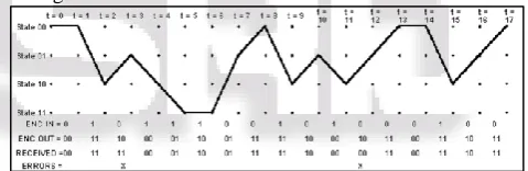
[image:3.595.310.547.238.328.2]Viterbi algorithm is basically implemented to decode the errors found in convolution encoded sequence. As discussed the Viterbi algorithm will make use of trellis structure in finding the coded sequence based on the transmission signals. Since each and every code sequence will follow based on the trellis process of encoding data. Considering an example of trellis diagram of half rate, three convolution encoder K=3 and 15 bit messages with four possible states shown in 4 horizontal rows with dotes.
Fig. 2: shows the Trellis Diagram of Viterbi Algorithm 18 columns shows the time instants from t0 to t17 both t=o and t=17 has the four dot column which is initial and final state situations while encoding messages. The state transition is shown with a dotted line at zero input. The figure shows the state of trellis, which reach the encoding of messages.
Fig. 3: shows States of the Trellis Diagram of Viterbi Algorithm
Maximum likelihood (ML) sequence will be obtained from the track of paths that occur for Viterbi algorithm is essential for processing information coding. The common aid to analyze the Viterbi algorithm is the trellis diagram. It is the decoding algorithm used with convolution code. The input, output, receiver and error details are shown at bottom to the figure. The receiver pair of the channel after collecting the complete information regarding the process the Viterbi decoder is ready to function with the bit that are to be transmission following some steps. Initially number of state is to be selected at a negligible collected error metric then save the number state arrived. Accurate performs of step from the initial trellis is to be achieved. All the state sequence state numbers are to be saved. Work forward with record of all the selected states which are saved in the previous steps which are to be built in by all the encoded convolution encoder.
F. Advantages of Viterbi Algorithm
[image:3.595.307.547.400.478.2]Viterbi algorithm. The usage of this Viterbi algorithm is found to be advantageous due to its cost effectiveness in modulated minimize at the same time the functional performance in some situation would modulate in maintaining the original cost. Emerging linear functioning of linear pulse distance is due to convenient source sequence.
III. RESEARCH ON PROPOSED SOLUTION
Research is generally defined as the human activity that is carried out based on the intellectual application in the investigation of matter. Basically there are various approaches for the researcher to finish their task successfully but these people select the approaches depending on their research objectives. For the present research, it’s better to prefer the secondary resources when compare to the primary resources. As the researcher may face problems while gathering the accurate
IV. ANALYSIS ON RESEARCH
Viterbi algorithm is extensively used decoder technique in digital communication systems because it secures the information message from the affects like noise, fading when transmitted from sender to receiver. Viterbi algorithm considers the regularly used symbols if the receiver gets the damaged sequence of symbols from the transmitter.
A. Analyzing the Results Obtained through VHDL Coding for the Implementation of Viterbi Algorithm
The implementation of Viterbi algorithm is somewhat difficult even though the process of algorithm is simple. Conventional encoding can be easily implemented on Viterbi algorithm even though there exist a large gap in complexity with the transmission side. State trellis uses conventional encoding, the decoder explores rotates between states because it is a finite state machine. It requires large memory registers for storing results. There is some delay in final decision on a sequence of transitions because of the size of the input code is very high. By observing the transition metrics between states the decision can be done and the results are updated in the form of Hamming distance or Euclidean with the error-corrupted received sequence.
B. Architecture of the Programmable Vd
The computation process of Viterbi decoder rises exponentially with the constraint size K. For raising size of k more hardware circuits are required for both treating power and memory .the reuse of resources for reducing the area occupancy and the operating frequency required by the UMTS standard is of primary concern. Three-bit soft decision has been adopted as quantized input: this alternative option represents a good trade-off compare complexity and accuracy The Viterbi decoder architecture mainly consists of three units.
1) Branch Metric Unit (BMU)
Calculation of the minimal length between the input pairs of bits and all the possible “ideal” pairs.
2) Path Metrics Calculation
For each decoder state, calculating for survivor ending in a metrics needed. Hence to obtain the survivor with the minimal metrics are to be noted.
3) Trace Back
[image:4.595.324.530.626.755.2]To obtain the desired results this is responsible step is to be simulated at the hardware implementations that don’t store the actual information regarding the survivor paths. But are stores one bit of information every time
Fig. 4: shows the Viterbi Decoder Data Flow
V. IMPLEMENTATION
A. Branch Metrics Calculations
The hard and the soft decision decoders are differ in calculating the branch matrices’. In the hard decision decoder, a hamming distance will be obtained between the ideal pairs and the received pairs. Therefore each pair has a branch metrics. A branch metrics is measured using Euclidean distance. Let x defines the first received bit in the pair, y the second, Hence the branch metrics will be.
1
2 The soft decision the actual results are not be needed as known absolute metric values. Only they differ in making sense.
In the next steps the branch metrics are to be calculated without hard ware multiplications.
*Need to be calculated without the hard ware implementations. The obtained x and y values are to be computed with the 2`complemant.
B. Path Metric Calculation
Path metric can be done by using ACS (Add-Compare-Select).this consists of repetition of each encoder state. 1) Add-out put response can be obtained by using the
previous results with matching path vales.
2) Compare, select-in this state system consist two path values, in that greater branch metric value should be leaved. Exists 2(-1) survivor paths for 2(-1) encoder states. the maximum difference cannot reach log-1, Where d represents the difference between minimum and maximum branch metrics
1) Trace Back
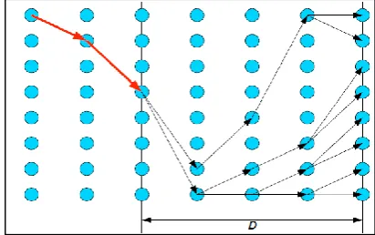
It has been said that all paths combined after decoding a large block of data as shown in the figure. That is they only differ in their endings and have same beginning.
In the graph of 4.2 the Blue circles represents the encoder states. It can be seen that all survivor paths have a common beginning (red) and there will differ only in their endings. If we want over decoder to have final latency, we have to decode a continuous stream of data. The decoding bits related to this part can be sent to output, as it is common that some of the part at the starting of the graph that belongs to all survivor path. From the above statement the decoding can be performed as follows:
1) Finding the survivor path for N+D input bits. 2) Send N bits to the output.
3) Find the survivor paths for another N pairs of input bits. 4) Trace back from the end of any survivor paths to the
beginning. 5) Go to step 2.
In this D parameter is important parameter and is called as decoding path. By increasing the D parameter there is a chance of decreasing of decoding error but also an increase in the latency.
The VD has been tested with a Nallatech extreme DSP Development Kit, and the appropriate results can be compared with both functional and MATLAB simulations. The maximum clock frequency is obtained for UMTS /GPRS after substitution and routing is equal to 32.26MHz.without using the trace-back method achieved faster implementation of Viterbi decoder. The extra resources used for reconfiguration procedure compared to fixed implementation is just 5%.this result is satisfied with procedures in Ref [17]. The main purpose of using Viterbi decoder is for fast switching between UMTS and GPRS decoding which is used in software radio applications .area can be reduced by reusing the resources.
VI. RESULTS
The input values for Viterbi encoder are specified in the developed code. Providing input every time for the developed design is time taking process. So, the input values are included directly in the developed code, so that simulation process can be executed directly. The Viterbi encoder input values given in this project are:
011010011001011010010110011010011001011001101001 011010011001011010010110011010010110100110010110 011010
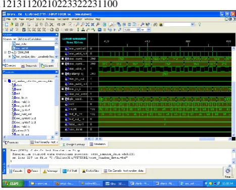
[image:5.595.314.546.68.231.2]Each input value will be processed and a corresponding output will be provided for the Viterbi encoder. The output values will be specified in the form of wave forms in both Xilinx and active HDL simulation environments
Fig. 6: Xilinx Simulation Environments for Viterbi Encoder and Decoder
A. Analysis of Simulation Using Xilinx
When clock signal is applied to the Viterbi decoder reset button is set as 0, and the system reset button kept as 0, the cyclic encoded data starts after 100ns.by applying the valid encoded pulse train to the decoder enc_symbol 0 and enc_symbol 1 varies according to the periodic pulse train. According to the enc_symbol the encoded output bit also a pulse train.
The dec_symbol0 consists an 3’h0 error bits at decoder process up to 100ns,after 100ns it decodes 3bits at a time changes continuously every 50ns.dec_valid_in is a continuous pulse train when dec_symbol is change their bit stream every after 100ns.thus we get dec_ out bit and dec_valid _out bits same as 1.the count of decoder is 103 and the buf_in_cnt as 102.from that the decoder buf_out_cnt and total count can be represented as 0 bit count
The concerned output for the above encoder is
031211211022332212022131231100111022332223110011 213112021022332212022131231100
112131120210223322231100
Fig. 7: Xilinx Simulation Results for Viterbi Encoder
B. Analysis of Simulation
[image:5.595.310.544.485.673.2]an encoded bit input value is set to ‘0’ then the results can be obtained as
100110100111000110111000
When an encoded valid input value is set to ‘0’ then the result can be obtained as
101010101010101010101010
When an encoded symbo0 value is given as ‘0’ then the results are
110111000000001111111111
For an encoded symbol1 if the value is set to 1 then the analyzed results are
111011110001111000111111
Now for a decoded symbol0 when the value is set to 7 then there will be periodic changes obtained in a de-mux as 7 0 7 0 7
And for decoded symbol1 when the value is given as 7 then the output is the demux value given as 0 7 0 7 0 7 0 7
When decoded valid input value is given as ‘0’ then the output is continues signal.
For a pattern value when given as ‘3’ then there will be no changes in the signal and similar appears when the decoded bit output, decoded valid output and decoded output error value is set to ‘0’.
When glb_seed value is set to 000E4048 then there appear a demux in the result. For ccnt, value is set to 1 then the result
104101010101010101010101010101010
And finally for buffer output count, total count and sim done value when set to ‘0’ the n there will be no changes in the signal.
Implementation of Viterbi encoder can also be simulated with the help of active HDL simulation environments. Active-HDL is an Aldec product developed using Field Programmable Gate Array (FPGA) with HDL simulator. The main reason for choosing this tool for simulation is that it can support graphical and text based designs with various simulation languages.
C. Synthesis and Implementation
[image:6.595.310.545.106.292.2]The design can be synthesized and implemented after verifying the design behavior with simulations. The process of synthesis and implementation can provide a clear view on how the developed code is working for obtaining simulation results
Fig. 4.5: Viterbi Decoder Synthesis
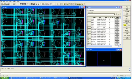
[image:6.595.309.548.342.495.2]The entire code developed for this project can be visualized using Xilinx hardware device. How the Viterbi algorithm code for encoder and decoder is working in a step by step process can be analyzed based on results of implementation.
Fig. 4.6: Design Layout for the Developed Code using Xilinx-ISE
[image:6.595.314.544.541.680.2]Checking the details of the design after implementing each and every action is necessary. Synthesis report can provide an opportunity to view all the resources utilized by the developed design
Fig. 4.7: Synthesis Report of the Design
Implementing the design in FPGA editor can provide the below results. This view is providing in-built working process and routing information.
[image:6.595.52.283.586.729.2]VII. CONCLUSIONS
As Viterbi algorithm is conceived more interesting and challenging for this research topic, it is considered, and also it has wide variety of applications in digital communications field. This research helps to generate more profits by the developers using Viterbi algorithm. Anyone besides students can easily analyze these Viterbi algorithm concepts and can gain more knowledge about it. This research mainly concerned with implementation of Viterbi algorithm using VHDL coding. Viterbi algorithm has many advantages like low power consumption and main advantage is error correcting using VHDL. Anyone reading this document will have to gain the cognition of working with different tools like Xilinx ISE and MODELSIM.
VIII. FUTURE SCOPE
By using FPGA device and hybrid microprocessor the decoding benefits can be achieved in future. Power benefits are provided by the integration of sequential decoding. To reduce the multipath fading which damages the signals, the adaptive array technique is used for future satellite communication. The solutions of the Adaptive Viterbi decoding calculate on the chosen noise level and algorithmic parameters. For independence on noise level and fixed complexity M-algorithm is used. In future to improve the decoder performance the adaptive Viterbi algorithm is carried out in reconfigurable hardware. [43]For power saving techniques can be used for the power saving architecture can be designed for the above decoder which is executable in the mobile devices. The non-binary codes can be implemented in the future for the Viterbi decoder. Viterbi decoder is now being implemented in XILINX in future it can also be implemented using JAVA. Therefore in the future Viterbi algorithm may be used for various scenarios. So in the future the complexity can be greatly reduced. By using M-algorithm decoding noise effects can also be greatly reduced.
REFERENCES
[1] R. E. Stake (1995) “The art of case study research”. USA: Sage.
[2] K.Aleksandar, M.F. Jose (2000) “The Viterbi Algorithm and Markov Noise Memory”. [Internet] available at URL:<http://www.ece.cmu.edu/~moura/papers/kavcic_ viterbinoisememory.pdf>, [accessed on20th November 2010].
[3] K. Hueske, J. Geldmacher, J. Gotze (2007) Adaptive decoding of convolutional codes, Copernicus Publications, pp. 209-214. Internet. (N.D) Coding in communication system.[Internet] available at URL: <http://www.mathdb.org/notes_download/elementary/n umber/ne_N6.pdf>, [accessed on20th November 2010].08)e: Sprnger.
[4] B. Tristan (2006) IMPLEMENTATION OF THE VITERBI ALGORITHM USING FUNCTIONAL PROGRAMMING LANGUAGES. [Internet] available
at URL:
<http://people.eecs.ku.edu/~esp/publications/c2009ItcT ristan.pdf>, [accessed on 20November 2010].
[5] K. Hucker (2001) Research Methods in Health, Care and Early Years. UK: Heinemann Publishers.
[6] Y. K. P.Cheung, G. A. Constantinides, J.T. D. Sousa (2003) Field-programmable logic and applications: 13th International Conference, FPL 2003, Lisbon, Portugal. New York: Springer.
[7] J. Kia (2005) What Is a Convolutional Encoder / Convolutional Encoding. [Internet] available at URL:
<http://www.askkia.com/articles/what-is-a-convolutional-encoderviterbi-algorithm.html>, [accessed on 20 th November 2010].
[8] G. Fettweis and H. Meyr, “Feedforward architecture for parallel viterbi decoding,” J. VLSI Signal Processing, vol. 3, pp. 105-119, 1991.
[9] G. Fettweis, H. Meyr, “High rate Viterbi processor: a systolic array solution,” IEEE J. SAC, Oct. 1990. [10] G. Fettweis, H. Dawid, and H. Meyr, “Minimized
method for Viterbi decoding: 600 Mb/s per chip,” in Proc. GLOBECOM 90, vol. 3, pp. 1712-1716,Dec. 1990. [11] G. Fettweis, L. Thiele, H. Meyr, “Algorithm transformations for ulimited parallelism,” Proc. IEEE ISCAS’90, 1756-59; also L Thiele, G.Fettweis, “-,” Electronics & Commun. no.2, 83- 91, 4/1990.
[12] A. P. Volnei (2004) Circuit design with VHDL. United States of America: MIT press.
[13] P. P. Chu (2006) RTL hardware design using VHDL: coding for efficiency, portability, and scalability. USA: John Wiley and Sons.
[14] Project seminar (2010) VHDL (VHSIC hardware description language) [Internet] available at URL: http://www.seminarprojects.com/Thread-vhdl-vhsic-hardwaredescription- language--14251#top>, [accessed on 20th November 2010]
[15] S. Kato, M. Morikura, S. Kubota, H. Kazama and K. Enomoto, “A TDMA satellite communication system for ISDN services,” Proc. Globecom’91, pp. 1533-1540, December 1991.
[16] K. Kawazoe, S. Honda, S. Kubota and S. Kato, “Ultra-high-speed and universal coding-rate Viterbi decoder VLSIC,” Proc. ICC’93, pp. 1434-1438, May 1993. [17] K. Koora, et. al, “ From algorithms testing to ASIC input
code of SOVA algorithm for Turbo codes,” Proceedings of Turbo-code seminar, 1996.
[18] S. Kubota, K. Ohtani and S. Kato, “A high-speed and high-coding-gain Viterbi decoder with low power consumption employing SST (scarce state transition) scheme,” Electron. Lett., 22 (9), pp. 491-493,1986. [19] L. Lang; C.Y. Tsui and R.S. Cheng, “Low power soft
output Viterbi decoder scheme for turbo code decoding,” Conference-Paper, ISCAS ‘97(Cat. No97CH35987). IEEE, New York, NY, USA, 4 vol. Lxvi+2832 pp. p. 1369-1372 vol.2, 1997.
[20] H.F. Lin and D.G. Messerschmitt, “Algorihtms and architectures for concurrent Viterbi decoding,” in Proc. ICC, pp.836-840, 1989.
[21] B.K. Min and N. Demassieux, “A versatile architecture for VLSI implementation of the Viterbi algorithm,” in Proc. ICASSP, pp. 1101-1104, May 1991.
Electronic-Letters, IEE, Vol.32, No.22, pp. 2198-2199, Oct. 1996.
[23] D. Oh, Y. Kim, and S. Hwang “A VLSI architecture of the trellis decoder block for the digital HDTV grand alliance system,” IEEE Trans. Consum. Electron, 42, (3) pp. 346-356, 1996.
[24] J.K. Omura, “On the Viterbi decoding algorithm,” IEEE Transactions on Information Theory, vol. IT-15, pp. 177-179, Jan 1969.
[25] K.K. Parhi, D.G.Messerschmitt, “Pipeline interleaving and parallelism in recursive digital filters,” IEEE Tr. ASSP, 1099-117, 7/89.
[26] Qualcomm, Inc., “Proposed EIA/TIA interim standard wideband spread spectrum digital cellular system dual-mode mobile station – base station compatibility standard,” April 21, 1992.
[27] C.M. Rader, “Memory management in a Viterbi decoder,” IEEE Transactions on Communications, vol. COM-29, pp. 1399-1401, Sept. 1981.
[28] R. Scheweikert, A.J.Vinck,”Trellis coded modulation with high-speed low complexity decoding,” submitted to IEEE GLOBECOM 1990.
[29] K. Seki; S. Kubota; M. Mizoguchi and S. Kato, “Very low power consumption Viterbi decoder LSIC employing the SST (scarce state transition) scheme for multimedia mobile communications,” Electronics-Letters, IEE, Vol.30, no.8, p.637-639, 14 April 1994. [30] C.B. Shung, P.H. Siegel, H.K. Thapar, and R. Karabed,