Abhishek Chittora, Amit Kumar, Ayushi Tikkiwal, Chetan Saini
Student, Electronics And Communication, Poornima College Of Engineering, Rajasthan, India Student, Electronics And Communication, Poornima College Of Engineering, Rajasthan, India Student, Electronics And Communication, Poornima College Of Engineering, Rajasthan, India Student, Electronics And Communication, Poornima College Of Engineering, Rajasthan, India
---***---Abstract
-The sizes and weights of various wirelesselectronic systems (e.g. mobile handsets) have rapidly reduced due to the development of modern integrated circuit technology. A Microstrip antenna (MSA) is well suited for wireless communication due to its light weight, low volume and low profile planar configuration which can be easily conformed to the host surface. However, MSAs suffers from low bandwidth. MSA bandwidth is greatly affected by the geometery and dimensions of the radiating microstrip patch. In this paper, the effect of various dimensions on rectangular microstrip patch antenna performance is investigated. By keeping the substrate thickness constant over various dimensions, simulations were carried out using IE3D software and EM Talk software. The results show that the dimensions effectively determine the performance of Microstrip Patch antenna.
Keywords:Microstrip Patch Antennas
1.0. INTRODUCTION
With the wide spread proliferation of wireless communication technology in recent years, the demand for compact, low profile and broadband antennas has increased significantly. To meet the requirement, microstrip patch antennas (MPAs) have been proposed. MPAs are widely used in wireless communication applications because of their low profile, lightweight, low cost and compatibility with integrated circuits (Guney and Sirikaya, 2004). However, the conventional MPA has a disadvantage of a narrow bandwidth. There are numerous and well-known methods of increasing bandwidth of this type of antennas, and amongst the most common ways varying the different dimensions of the radiating patch of antenna.However, the bandwidth and the size of an antenna are generally mutually conflicting properties, that is, improvement of one of the characteristics normally results in degradation of the other. A thick dielectric substrate having a low dielectric constant is more desirable as it provides better efficiency, larger bandwidth, and better radiation (Indrasen Singh et al,2011).
There are numerous geometries and dimensions of the radiating patch that can be used for the design of MPAs and their dielectric constants are usually in the range of 2.2 ≤ εr ≤ 12 . The radiation increases with frequency increase and using thicker substrates with lower permittivity, and originates mostly at discontinuities. The dielectric constant is the ratio between the stored amount of electrical energy in a material and to that stored by a vacuum. It is also a measure of the degree to which an electromagnetic wave is slowed down as it travels through the insulating material (Mutiara et al, 2011). Dielectrics are used in capacitors to store more electrical charge than vacuum. The lower the dielectric constant is, the better the material works as an insulator, and the better an insulator, the better it resists electrons from being absorbed in the dielectric material, creating less loss (Mutiara et al, 2011; Balanis, 1997). Radio frequency (RF) applications are characterized by the need for low dielectric losses, low leakage, and low and uniform dielectric constant accompanied by a low layer count. Choosing a material based on its dielectric constant characteristics and losses usually dominates over other considerations.
2.0. RECTANGULAR MICROSTRIP PATCH ANTENNA DESIGN
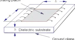
[image:1.595.398.525.661.730.2]In its most basic form, a microstrip patch antenna consists of a radiating patch on one side of a dielectric substrate and a ground plane on the other side as shown in Figure 1. The bottom surface of a thin dielectric substrate is completely covered with metallization that serves as a ground plane.
Figure 1: Structure of a Rectangular Microstrip Patch Antenna The rectangular MSA is made of a rectangular patch with
dimensions width (W) and length (L) over a ground plane
© 2015, IRJET.NET- All Rights Reserved Page 1701
PERFORMANC
E
OF A RECTANGULAR
MICROSTRIP PATCH
with a substrate thickness ( and dielectric constant as shown in Figure 1. There are numerous substrates that can be used for the design of MSAs, and their dielectric constants are usually in the range of 2.2 < εr < 12.
The steps followed in the design of rectangular MSAs as discussed in (K. Guney and N. Sirikaya, 2004; Balanis, 1997; Saeed and Sabira, 2005; Dafalla, 2004) are as follows;
The Patch Width (W) for efficient radiation is given as;
W= 2f0
where, W is the patch width, vo is the speed of light, fr is
the resonant frequency, an d is the dielectric constant of the substrate
The Effective Dielectric Constant ( ) - Due to the fringing and the wave propagation in the field line, an effective dielectric constant (εreff) must be obtained.
=
where, εreff is the effective dielectric constant, h is the height of the
dielectric substrate
The Effective Length ( ) for a given resonance frequency fr is
given as;
= s
The Length Extension ( ) is given as;
=
The Patch Length (L). The actual patch length now becomes;
The Bandwidth (BW)
where, is the wavelength in free space.
The Feed Co-ordinates. Using coaxial probe-fed technique, the feed points are calculated as;
Yf = W/2
Xf = L
where, yf and xf are the feed co-ordinates along the patch width and
length respectively
The Plane Ground Dimensions:- It has been shown that MSAs produces good results if the size of the ground plane is greater than the patch dimensions by approximately six times the substrate thickness all around the periphery (Balanis, 1997; Dafalla, 2004).
Lg = 6h + L
(9)
where, Lg and Wg are the plane
ground dimensions along the patch length and width respectively.
3.0. SIMULATION RESULTS AND DISCUSSION By using IE3D , simulation was carried out to generate the values of various rectangular MSA parameters namely patch width, patch length, and feed points. Also, simulation was carried out using IE3D and EM talk software and the results tabulated and plotted.
Figure 2 to 5 plots various MPA parameters (Patch Width, Patch Length, and Feed Point) with relation to resonant frequency. We have designed three rectangular patch antenna with transmission line feeding technique but the dimensios of all three antennas vary. The shape and dimensions of the patch are as following and named as A!,A2 and A3:
A1-
Parameters-
• Width-47mm
• Length-52mm
• Thickness-1.59mm
• Dielectric constant-4.4
[image:3.595.313.515.90.276.2]• Feeding technique-transmission line
Figure 2: Shape of a Rectangular Microstrip Patch Antenna; A1
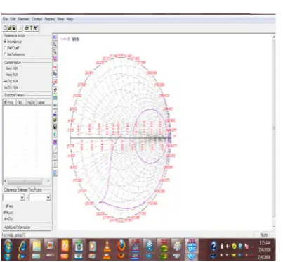
Impedance-
Figure 3: Impedance of a Rectangular Microstrip Patch Antenna; A1
A2-
Parameters-
• Width-49mm
• Length-50mm
• Thickness-1.59mm
• Dielectric constant-4.4
• Feeding technique-transmission line
• Resonant Frequency-1.5Ghz,2.996Ghz
Figure 4: Shape of a Rectangular Microstrip Patch Antenna; A2
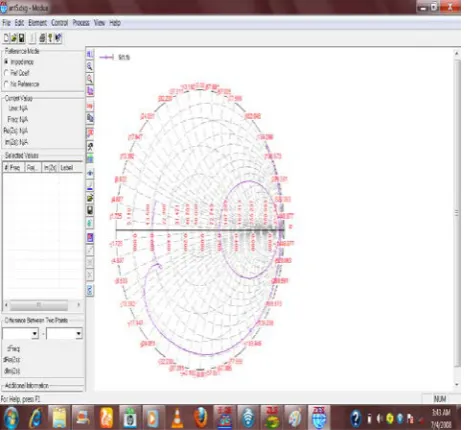
[image:3.595.312.542.428.615.2]Impedance-
Figure 5: Impedance of a Rectangular Microstrip Patch Antenna; A2
Wg = 6h + W
(10)
[image:3.595.29.254.519.664.2]A3-
Parameters-
• Width-45mm
• Length-50mm
• Thickness-1.59mm
• Dielectric constant-4.4
[image:4.595.333.534.157.289.2]• Feeding technique-transmission line
Figure 6: Shape of a Rectangular Microstrip Patch Antenna; A3
Impedance-
Figure 7: Impedance of a Rectangular Microstrip Patch Antenna; A3
Comparison between VSWR outputs of different antennas A1, A2 and A3-
Figure 5: Comparison between VSWR outputs of different antennas A1,A2 and A3
Comparison between Return Loss outputs of different antennas A1, A2 and A3-
[image:4.595.30.267.214.396.2] [image:4.595.30.265.467.682.2]Overall comparison between four rectangular patch antenna- Anten na Name Width
(mm) Length(mm) Frequency (Ghz)
VSWR Retur
n Loss (db)
A1 47 52 1.5,
2.992 1.76263,
1.1650 9 -11.155 4, -24.656
A2 49 50 1.5,
2.996 9.27753,
3.1264 7 -1.8688 5, -4.8524
A3 45 50 1.5,
2.996 12.3411,
3.6206 2 -1.4023 8, -4.9286 4.0 CONCLUSION
The performance of antenna depends on its dimensions(length, width and thickness),which can be seen from the above comparison graphs that out of the three different antennas simulated using IE3D software .In antenna A1, the resonant frequency are 1.5 and 2.992Ghz and VSWR is 1.7 and1.16 and the return loss of the same is -11.1557 nad -24.656 but in case of antenna A2 when the width is increased to 49mm and length is decreased to 50mm then the frequency becomes 1.5 and 2.996 and VSW 9.27753 and3.12647 and return loss -1.86885 and -4.8527 and in antenna A3, with length 50mm width 45mm and frequency 1.5 and 2.996 and VSWR 12.3411 and 3.62062 and return loss -1.40238 and -4.9286.
REFERENCE-
1. Ahamed Maruf et.al.(2012). Rectangular Microstrip Patch Antenna at 2GHz on Different Dielectric Constant for Pervasive Wireless Communication. International Journal of Electrical and Computer Engineering, Vol. 2, No. 3, pp. 31-39.
2. Ali Dheyab and Karim Hamad (2011). Improving Bandwidth of Rectangular Patch Antenna using Different
3. Thickness of Dielectric Substrate. ARPN Journal of Engineering and Applied Sciences, Vol. 6, No. 4, pp. 16-21.
4. Balanis, Contantine A. (1997). Antenna Theory – Analysis and Design. John Wiley & Sons Inc., 2nd Edition, pp. 722
5. Dafalla (2004). Design of a Rectangular Microstrip Patch Antenna at 1GHz. RF and Microwave Conference, Subang, Selangor, Malaysia, pp. 145-149.
6. D. D. Sandu et.al.(2003). Microstrip Patch Antenna with Dielectric Substrate. Journal of Optoelectronics and Advance Materials, Vol. 5, No. 5, pp. 1381-1387.
7. Guney and N. Sirikaya, (2004). Adaptive Neuro-Fuzzy Infrerence System for Computing of the Resonant Frequency of Circular Microstrip Antennas. Aces Journal, Vol. 19, No. 3, pp. 188-197. 8. Mutiara et al, (2011). Design of Microstrip
Antenna for Wireless Communication at 2.4 GHz. Journal of Theoretical and Applied Information Technology, Vol. 33, No. 2, pp. 184-192.