Self-balancing
Robot
Control
Using
Fractional-Order
PID
Controller
K. Kankhunthod,
V.
Kongratana,
A.
Numsomran
and
V.
Tipsuwanporn,
Member,
IAENG
Abstract—This paper presents a two-wheeled robot control that can balance upright on its own by controlling the angular speed of the motor to keep the robot upright using measured data from the gyroscope sensor. The aim of this study is to demonstrate the design of fractional-order PID controller (FOPID) that has more controllability and the ability to adjust outperform traditional PID controller. The design of optimal FOPID controller based on integer-order PID parameters are explained and validated its performance compared with the traditional PID controller using Matlab simulation. As well as the real system experiment is implemented on Raspberry Pi using IIR filters cascaded second-order section form II. The study revealed the appropriate concept of implementation of FOPID on the real system.
Index Terms—two-wheels self-balancing robot, raspberry pi, control system, fractional-order PID controller, digital IIR filter
I. INTRODUCTION
S
ELF-balancing robot is standing on two-wheels and keeps itself balance without falling as well-known small personal transporter called “Segway”. Self-balancing robot basedonan invertedpendulumtheoryisapopularresearch topic in several years. An inverted pendulum is a chal-lenge control problembecause thesystemisnon-linear and completely unstable [1]. To control the robot upright, the external force form motor is needed to compensatefor the angulardisplacementoftherobot.Themostimportantpartto stabilizetherobot’ssystemisacontroller.Themostwidely usedandsimplecontrollerisaPIDcontroller (proportional-integral-derivativecontroller)whichappropriatesfor improv-ing both transient and steady-stateresponses. However, the PID controller is less effective with high order and high external noise system [2]. This paper introduces fractional order PID controller (FOPID) PIλDµ controller based onfractionalcalculus.Thenon-integeroperatorsλandµarethe order of integral and derivative parts respectively, therefore FOPIDhavemoreadjustableparametersthantraditionalPID so that it has higher performancetocontrol highorderand delay time system, especially the performance of the non-linearcontrolsystemovercometraditionalPIDcontroller[3]. FOPIDwillbedeeplydescribedinsectionII.Therearemore authorseveralapproachesaboutaself-balancingrobotfollow
K. KankhunthodisamasterofengineeringstudentwithInstrumentation Engineering,FacultyofEngineering,KingMongkut’sInstituteof Technol-ogyLadkrabang,Bangkok,Thailand.
Assoc. Prof.V.Kongratana iswith theDepartment ofInstrumentation andControlEngineering,FacultyofEngineering,KingMongkut’sInstitute ofTechnologyLadkrabang,Bangkok,Thailand.
Assoc.Prof.Dr.A.NumsomraniswiththedepartmentofInstrumentation andControlEngineering,FacultyofEngineering,KingMongkut’sInstitute ofTechnologyLadkrabang,Bangkok,Thailand.
Assoc.Prof.Dr.V.TipsuwanporniswiththeDepartmentof Instrumen-tation andControlEngineering, FacultyofEngineering, KingMongkut’s Institute of Technology Ladkrabang, Bangkok, Thailand. (e-mail: [email protected]).
Fig.1. Self-balancingrobot.
literaturereviews[4-8]InsectionII,wewilldiscusstheories relatedtothispaperincludeoffractional calculus,fractional order PIλDµcontroller, digital IIR filter, and Kalman filter thatnecessarytoeliminatethemeasurementerrorfromthetilt sensor. Section III discusses in mechanical structure, mathematical model, and state-space of the robot. SectionIV demonstrates PID and FOPID controller design and their simulation results. Section V demonstrates to realizationimplemented both controllers on the real system andresultof PIDcontrolleronthe realsystem.
II. THEORIESRELATEDTOTHESELF-BALANCING ROBOT
A. Fractional Calculus
As far as we know that the conventional calculus has integer orders for both derivative and integral operations while the fractional-order calculus has non-integer order operationsaDαt in (1).
aDtα=
dα dtα
1 Rt
a(dt)
−α
<(α)>0,
<(α) = 0,
<(α)<0,
(1)
wherea, tdenote the limits of the operation and αdenotes the fractional order. The fractional differ-integral has multi-definitions [9] as follows:
1) Riemann-Liouville definition [10]:
aDtαf(t) =
1 Γ(m−α)
d dt
mZt
a
f(τ)
(t−τ)α−m+1dτ (2)
Form−1< α < m, m∈N whereΓ(·)is Euler’s gamma
Function.
2) Gr¨unwald-Letnikov definition:
Dαtf(t) = lim
h→0
1
hα
[t−a h ]
X
j=0
(−1)j α
j
In equation (3) part inside [] are integer. The Laplace trans-form of αth order derivative of a signal x(t) withα∈R
+
(assuming zero initial conditions) is given by (4).
L {Dαx(t)}=sαX(s). (4)
B. Fractional-orderPIλDµcontroller
Fractional PID controller or FOPID is well known as
PIλDµcontrollerbasedonthefractionalcalculus,λandµare
non-integerorderofintegralandderivativepartrespectively, thereforFOPIDhastotalfiveparameters(Kp,Ki,Kd,λand
µ) cause abilityto controlthe dynamic system precisely.In (5), u(t)is FOPID control input intime domainand Gc(s)
denotesthefractional-orderPIDcontrollertransferfunction.
u(t) =Kpe(t) +KiD−λe(t) +KdDµe(t) (5)
Gc(s) =Kp+
Ki
sλ +Kds
µ (6)
When taking λ = µ = 1 result is the traditional PID controller.
C. Kalman Filter
Kalman filter introduced by Rudolph E. Kalman in 1960 is the best well know filter theory [11] and widely used [12]. Kalman filter is kind of pure time domain filter which differs from most filter like a low-pass filter that is a frequency domain designed [13]. Kalman filter can eliminate noise and recover the real data by comparing error covariance between previous (7) and current states (8) [11]. Kalman filter time update equation:
(7)
Kalman filter measurement update equation:
(8)
WhereA, Bare parameters of state,Q, Rdenote error co-variance of process and measurement respectively,Pdenotes an estimated error covariance, K is Kalman filter gain, H is predicted measurement, more information about Kalman filter in [12] and about self-balancing robot with Kalman filter are in [14, 15].
D. Digital IIR Filters
Infinite impulse response (IIR) filter contain feedback paths that can keep infinite impulse response [16]. IIR filter can be model in transfer function form, H(z)that consists of poles (bi) and zeros (ai), as the following Equation.
H(z) =k
PM
i=0biz−i
1 +PN
i=1aiz−i
(9)
IIR cascaded second-order section form II transfer function defined as follows.
H(z) =k×
N−1
Y
n=0
bn[0] +bn[1]z−1+bn[2]z−2
1 +an[1]z−1+an[2]z−2
(10)
Where N is the number of sections,bnis the set of forward
coefficients, and an is the set of reverse coefficients. To
implement the PID controller on the microcontroller, the transfer function of controller is replaced by the IIR cascaded second-order section form II filter because it has less delay term than IIR filters described in (10) which will be discussed in the implementation section.
III. MODELING FORSELF-BALANCINGROBOT AND STATE-SPACEREPRESENTATION
A. Mechanical Struction
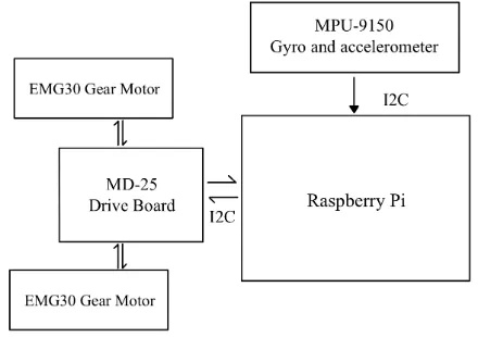
[image:2.595.316.536.431.586.2]The Structure of the self-balancing robot is shown in Fig.1. The chassis of the robot made by 4 threaded rods, layered with 3 mm acrylic plates for the equipment installed. Raspberry Pi 3 model B is used as the main controller because it’s tiny high-performance computer with 1.4 GHz, 64-bit quad-core processor [8], low power consumption with an ability to wirelessly access from another device over the same network that allows monitoring parameters while the robot is operating. The angular position and angular acceleration obtained from MPU-9150 Gyroscope and also accelerometer etc. It can communicate via I2C protocol. EMG30 gear motor with built-in encoder [17] and MD-25 drive board [18] designed for EMG30 was used as main drive system that also communicates via I2C. as shown by Fig.2. Gonc¸alves et. al. [19] have modeled EMG30 gear motor both mechanical and electrical and simulation resulted in estimated parameters of this motor that have been using in the simulation section of this paper.
Fig. 2. Structure of Self-Balancing Robot.
B. Mathematical model of self-balancing robot
The mathematical model of robot is separated into 3 parts as follows.
1) DC motor’s model: The circuit of a DC motor show in Fig.3
Fig. 3. Circuit of a DC motor.
Kk =Pk−H
T(HP−
k H
T +R)−1
xˆk=xˆ−k +Kk(zk−Hxˆ−k)
Pk= (I−KkH)Pk−
xˆ−k Pk−
=Axˆk−1+Buk
Equation.11 represent Kirchhoff’s voltage law of DC mo-tor where Va is voltage applied to DC motor, R and L are
equivalent resistance and inductance respectively,iis motor current,Ve is back emf voltage.
Va=Ri+L
di
dt +Ve (11)
Back emf voltage e V is a linear function of shaft angular velocity ,ω as show in (12).
Ve=keω (12)
Torque produced from a DC motor and total torque are represented in (13) and (14) respectively.
τm=itotalkm (13)
τtotal=τm−τf (14)
Where τm is no load torque produced from motor, τf
is friction torque, τtotal is total current of a motor. Then
combine (13) and (14) we get the relation between total torque and total current show in (15).
τtotal=itotalkm−τf (15)
τtotal=
(Va−Ve)
R km−τf (16)
Substitute (12) into (16) the governing equation of DC motor obtained (17). IR is moment of inertia of a wheel.
˙
ω= kmVa
IrR
−kmkeω
IrR
−τf
Ir
(17)
Equation (18) and (19) are state and output equations of state-space model
˙ θ ˙ ω
=
0 1 0 −kmke
IWR
θ ω
+
0 0
km IWR −
1 IW
Va
τf
(18)
y =
1 0
θ ω
+ 0 0
Va
τa
(19)
2) Robot’s Model: As mentioned previously, self-balancing robot’smodel is also called two-wheels inverted pendulumthathassimilarbehaviortotheinvertedpendulum oncart’smodel[20].Thecart’smodelwasreplacedwithtwo wheelsdescribedas follows.
Consider each left and right wheel applied Newton’s secondlawandtherelationbetweentorque,force,andradius the equations of left and right wheel obtained represent in (20) and(21).
MW¨x=
km
RrVa−
kmke
Rr2 x˙ −
IW
r2x¨−HL (20)
MWx¨=
km
RrVa−
kmke
Rr2 x˙−
IW
r2 x¨−HR (21)
Combining both (20) and (21) we have:
2
MW +
IW
r2
¨
x=2km
Rr Va−
2kmke
[image:3.595.327.524.53.152.2]Rr2 x˙−(HL+HR) (22)
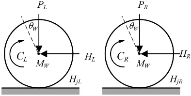
Fig. 4. Free body diagram of robot’s wheels.
[image:3.595.332.488.233.386.2]3) Chassis’s model: According to part of inverted pen-dulum model in the free body diagram of chassis shown in Fig.5
Fig. 5. Free body diagram of robot’s chassis.
The Equations of robot’s chassis calculated and integrated with the DC motor’s model (for more information see also [20], [21]) shown as follows.
(IP+l2MP)¨θP−2kRrmkex˙+2kRmVa+MPglsinθP
=−MPlx¨cosθP
(23)
2km
Rr Va = (2MW + 2IW
r2 +MP)¨x+2kRrmkex˙ +MPlθ¨P cosθP −MPlθP2 cosθP
(24) Linearize system with vertical upward equilibrium posi-tion condiposi-tion, θ = π, if ϕ denotes the deviation of the pendulum’s position from equilibrium (assume as a small deviation), that is, θP = π+ϕ then we get the following
conditions.
cosθP = cos(π+ϕ)≈ −1 (25)
sinθP = sin(π+ϕ)≈ −ϕ (26)
( ˙θP)2= ( ˙ϕP)2≈0 (27)
Then substitute approximations in (25), (26) and (27) into (23) and (24) result to two main governing equations as follows.
¨
ϕ= MPl
(IP+l2MP)x¨+
2kmke Rr(IP+l2MP)x˙−
2km R(IP+l2MP)Va
+ MPgl (IP+l2MP)ϕ
(28)
¨
x= MPl
2IW
r2 +MP+2MW ϕ¨−
2kmke Rr22IW
r2 +MP+2MW x˙
+ 2km R2IW
r2 +MP+2MW Va
(29)
˙ x ¨ x ˙ ϕ ¨ ϕ
=
0 1 0 0
0 2kmke(MPlr−IP−MPgl2) Rr2α
MPgl2
α 0
0 0 0 1
0 2kmke(rβ−MPl) Rr2α
MPglβ
α 0
x
˙ x ϕ ˙ ϕ
+
0
2km(−MPlr+IP+MPl2) Rrα
0
2km(−rβ+MPl) Rrα
(30)
y=
1 0 0 0 0 0 1 0
x
˙ x ϕ ˙ ϕ
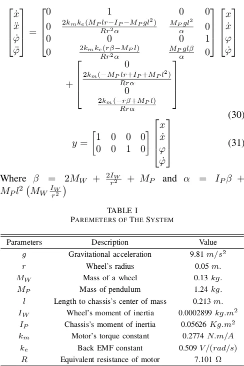
(31)
Where β = 2MW + 2rI2W + MP and α = IPβ +
MPl2 MWIrW2
TABLE I
PAREMETERS OFTHESYSTEM
Parameters Description Value
g Gravitational acceleration 9.81m/s2
r Wheel’s radius 0.05m.
MW Mass of a wheel 0.13kg.
MP Mass of pendulum 1.24kg.
l Length to chassis’s center of mass 0.213m. IW Wheel’s moment of inertia 0.0002899kg.m2
IP Chassis’s moment of inertia 0.05626Kg.m2
km Motor’s torque constant 0.2774N.m/A ke Back EMF constant 0.509V /(rad/s) R Equivalent resistance of motor 7.101Ω
IV. CONTROLLERDESIGN ANDSIMULATIONRESULT This section discusses the design technique of PID and FOPID controller and then simulate and compare control results using Simulink at the end of this section.
A. PID controller design
After state-space and parameters of self-balancing robot obtained in the previous section. The PID controller’s gains (Kp, Ki, Kd) obtained by minimizing the difference between
reference position (ϕ= 0, balance in vertical upward) and actual output using trial and error method based on mathe-matical model and balance ability of real robot’s system.
[image:4.595.47.291.64.429.2]Step 1: Create a closed-loop control system in Simulink represented in Fig.6, Auto-tune parameters using PID con-troller toolbox with 30-degree initial condition, adjusting proper response time and transient behavior. Controller out-put value required between -12 to 12 V. Too fast response time and strong transient behavior lead to the insufficient torque produced by two motors cause the robot can’t keep itself upward.
Fig. 6. Block diagram of closed-loop control.
Step 2: Applying PID controller gains to Raspberry Pi board using block diagram language available in CODESYS V3.5 (discussing at section V), start step 1 over again until achieving the best result. Optimal PID gains represented in Table II.
B. FOPID controller design
The design of FOPID controller performed by fraction-alorder PID controller optimization tool form FOMCON toolbox for MATLAB called by command fpid_optim
using the following steps.
Step 1: Convert state-space of the system to transfer function usingss2tf()for optimizing by FOPID controller optimization toolbox.
Step 2: FixKp, Ki, Kd with optimized integer-order PID
parameters obtained from section A.λ, µ= 1and set search limit for λ = [0.01,10], µ = [0.01,2], controller output = [−12,12].
Step 3: Using integrate square of error (ISE) performance matrix for faster response. Set setpoint to 0.078 rad (small deviation angle because fpid_optim toolbox focuses on transfer function optimization with zero initial condition there is not possible to set the setpoint to 0). Optimal FOPID controller’s parameters are also represented in Table. II
TABLE II
PARAMETERS OF THECONTROLLER
Parameters PID controller FOPID controller
Kp 194.534 194.534
Ki 1432.586 1432.586
Kd 5.551 5.551
λ 1 1.357
µ 1 0.803
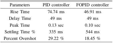
The simulation results of both controllers with 2 sec simulationtimecomparedinFig.7,Fig.7andTableIII.show that the result of closed-loop control with proper FOPID controller (red line) overshoot improved from 29.22% to 18.45%, rise time decreases from 74.74 ms to 46.91 ms compared withinteger-order PID controller. The fractional-orderPIλDµcontrollercanachievethesystemstability,great transient response and robustness compared with con-ventionalPID controller.
[image:4.595.336.516.402.475.2]Fig. 8. Control signal of PID and FOPID controller.
TABLE III
RESULT SPECIFICATION OFPIDANDFOPIDCONTROLLER
Parameters PID controller FOPID controller
Rise Time 74.74 ms 46.91 ms
Delay Time 49 ms 49 ms
Peak Time 0.13 sec 0.10 sec Settling Time % 335 ms 544 ms Percent Overshot 29.22 % 18.45 %
V. FOPID CONTROLLERIMPLEMENTATION ONREAL SYSTEM
[image:5.595.48.288.56.189.2]This section briefly demonstrates implementation of the controller into microcontroller board (Raspberry Pi 3) in term of IIR cascaded second-order section form II transfer function using CODESYS V3.5 Fig.9 represent the concept of a closed-loop control system of the self-balancing robot.
Fig. 9. Block diagram of closed-loop control.
Using PID implementation MATLAB toolbox pidim to convert continuous PID controller and Fractional-order PID controller to discrete-time transfer function with zero-order hold discretization method and convert to IIR cascaded second-order section form II matrix byd2sos()as follows.
PID controller:
FOPID controller:
[image:5.595.308.548.261.437.2]Create IIR cascaded second-order section form II function block using CODESYS V3.5 for controlling real system of the self-balancing robot the angular displacement of the robot with PID and FOPID controller shown in Fig.10 and Fig. 11
Fig. 10. Angular displacement of robot with PID controller.
Fig. 11. Angular displacement of robot with FOPID controller.
Fig.10 represents raw angle measured from MPU-9150 gy-roscope (blue line) and noiseless angle filtered by Kalman’s filters (red line). The result has shown that the angular displacement controlled by the PID controller of the robot is oscillated with amplitude less than±5degree and keep the robot upward.
[image:5.595.71.268.274.349.2] [image:5.595.307.550.488.636.2]Unfortunately, therehave two main problemswith this im-plementation.First, thecomplexityof calculationandmany loops per task circle cause the process slow response. The robotcan’tbalanceitself.Second,because ofi2c communi-cation, weused inthispaperislimited speed.
VI. CONCLUSION
Fractional-order PIλDµ controller (FOPID) for the
self-balancing robothas been studied on thispaper. The proper FOPIDparametersobtainedbyFOMCONtoolboxfor MAT-LAB based on proper integer-order PID parameters to achievingsystemperformanceandstabilityusingMATLAB and SIMULINK. The realize implementationon Raspberry PiconceptforbothcontrollershasbeenintroducedusingIIR cascaded second-order section form II transfer function in filterformonCODESYSV3.5,Intheoreticalterm.simulated results show that the FOPID controller can stabilize the system and improve transient response with less percent overshoot and rise time than PID controller. Whereas the implementation of PID controller on real robot systemcan keep the robot stablebetter than FOPID controller because ofthisimplementationonraspberryormicrocontrollerusing numericalmethodof filterl eadt oo verc omputinga ndslow overallprocess.TheFOPIDimplementationonRaspberryPi hasbeen studying inthe future.
The future study will focus on the implementation of fractional-order PID controller on a microcontroller board (RaspberryPi),theimprovementofprogramcyclespeedfor FOPID controller calculation and communication speed of robot’scomponents.
REFERENCES
[1] R.S. Voliansky and A.V. Sadovoi, “Second order sliding mode control of the inverted pendulum,”Proceedings of 2017 International Conference
on Modern Electrical and Energy Systems (MEES), Nov. 2017. pp.
224-227.
[2] O. Saleem and F. Abbas, “Nonlinear self-tuning of fractional-order PID speed controller for PMDC motor,”2017 13th International Conference
on Emerging Technologies (ICET), Islamabad, 2017, pp. 1-6.
[3] S. Jiang, M. Li and C. Wang, “Design and simulation of fractional order PID controller for an inverted pendulum system,”2017 IEEE Interna-tional Conference on Manipulation, Manufacturing and Measurement
on the Nanoscale (3M-NANO), Shanghai, 2017, pp. 349-352.
[4] M.I. Ali and M.M. Hossen, “A two-wheeled self-balancing robot with dynamics model,”2017 4th International Conference on Advances in
Electrical Engineering (ICAEE), Dhaka, 2017, pp. 271- 275.
[5] S. Wenxia and C. Wei, “Simulation and debugging of LQR control for two-wheeled self-balanced robot,”2017 Chinese Automation Congress
(CAC), Jinan, 2017, pp. 2391-2395.
[6] B. Shilpa, V. Indu and S.R. Rajasree, “Design of an underactuated self balancing robot using linear quadratic regulator and integral sliding mode controller,”2017 International Conference on Circuit ,Power and
Computing Technologies (ICCPCT), Kollam, 2017, pp. 1- 6.
[7] R. S. Martins and F. Nunes, “Control system for a self-balancing robot,”
2017 4th Experiment @International Conference (exp.at’17), 2017, pp.
297-302.
[8] Emil Eriksson (2016) Self-Balancing Robot Control System
in CODESYS for Raspberry Pi (Bachelor’s Thesis), Ume˚a
University, Ume˚a, Sweden. Retrieved from http://www.divaportal. org/smash/record.jsf?pid=diva2:1090623
[9] A. Tepljakov, E. Petlenkov and J. Belikov, “FOMCON: a MATLAB toolbox for fractional-order system identification and control”
Interna-tional Journal of Microelectronics and Computer Science, vol. 2, no.
2, pp. 5162, 2011.
[10] C.A. Monje, Y. Chen, B. Vinagre, D. Xue, and V. Feliu, “Fraction-alorder Systems and Controls: Fundamentals and Applications” ser. Advances in Industrial Control. Springer Verlag, 2010.
[11] H. Cheng, J. Xiao, Y. Long and T. Zhang, “Wind pendulum modeling based-on improved PID algorithm,” 2016 IEEE 11th Conference on
Industrial Electronics and Applications (ICIEA), Hefei, 2016, pp.
2288-2293.
[12] Greg Welch and Gary Bishop. 1995. “An Introduction to the Kalman Filter”Technical Report. University of North Carolina at Chapel Hill, Chapel Hill, NC, USA.
[13] K. Liu, M. Bai and Y. Ni, “Two-wheel self-balanced car based on Kalman filtering and PID algorithm,” 2011 IEEE 18th International
Conference on Industrial Engineering and Engineering Management,
Changchun, 2011, pp. 281-285.
[14] L. Ouyang, B. Du, A. Peng and Y. Ou, “Design of a Wheeled Inverted Pendulum as a platform for learning based control,”2012 IEEE
International Conference on Information and Automation, Shenyang,
2012, pp. 418-421.
[15] O.K. Sayidmarie, M.O. Tokhi and S.A. Agouri, “Real-time validation of a novel two-wheeled robot with a dynamically moving payload,”The 23rd IEEE International Symposium on Robot and Human Interactive
Communication, Edinburgh, 2014, pp. 102-105.
[16] Steve Winder, Chapter 17 – IIR filter design, Editor(s): Steve Winder,
InEDN Series for Design Engineers, Analog and Digital Filter Design
(2nd Edition), Newnes, 2002, pp. 395-408, ISBN 9780750675475
[17] R. Electronics, “EMG30, mounting bracket and wheel specification: Robot Electronics,” 2016. [Online]. Available:
http://www.robotelectronics. co.uk/htm/emg30.htm. [Accessed 16
May 2018].
[18] R. Electronics, “MD25 Technical Documentation: Robot Elec-tronics,” 2016. Available: https://www.robot-electronics.co.uk/htm/
md25tech.htm., [Accessed 16 May 2018].
[19] Gonc¸alves, J., Lima, J., Costa, P. and Moreira, A. “Modeling and Simulation of the EMG30 Geared Motor with Encoder Resorting to SimTwo,”The Official Robot@Factory Simulator. Advances in
Sustain-able and Competitive Manufacturing Systems,pp.307-314.
[20] MathWorks. 2012. “Control Tutorials for MATLAB and SIMULINK, Inverted Pendulum.” Available at:
http://ctms.engin.umich.edu/CTMS/index.php.exampleInvertedPendul
umsection-SystemModeling.[Accessed 13 May 2018]
[21] O. Jamil, M. Jamil, Y. Ayaz and K. Ahmad, “Modeling, control of a two-wheeled self-balancing robot,” 2014InternationalConferenceon
RoboticsandEmergingAlliedTechnologiesinEngineering(iCREATE),
Islamabad, 2014, pp. 191-199.
Modification date : 28 May 2019
editing detail:
1. author's name below the name of the paper. old version: "K.Kankhunthodl" edited version: "K. Kankhunthod" 2. Change the wrong word.
edit the wrong symbol of the Fractional-order PID controller from "P^(lambda) ID^(mu) Controller" to
the colected word "PI^(lambda)D^(mu) Controller"