Accelerating Somewhat Homomorphic Evaluation using FPGAs
Erdin¸c ¨Ozt¨urk1, Yarkın Dor¨oz2, Berk Sunar2and Erkay Sava¸s3 1
Istanbul Commerce University 2
Worcester Polytechnic Institute 3
Sabancı University
Abstract. After being introduced in 2009, the first fully homomorphic encryption (FHE) scheme has created significant excitement in academia and industry. Despite rapid advances in the last 6 years, FHE schemes are still not ready for deployment due to an efficiency bottleneck. Here we introduce a custom hardware accelerator optimized for a class of reconfigurable logic to bring LTV based somewhat homomorphic encryption (SWHE) schemes one step closer to deployment in real-life applications. The accelerator we present is connected via a fast PCIe interface to a CPU platform to provide homomor-phic evaluation services to any application that needs to support blinded computations. Specifically we introduce a number theoretical transform based multiplier architecture capable of efficiently handling very large polynomials. When synthesized for the Xilinx Virtex 7 family the presented architecture can compute the product of large polynomials in under 6.25 msec making it the fastest multiplier design of its kind currently available in the literature and is more than 102 times faster than a software imple-mentation. Using this multiplier we can compute a relinearization operation in 526 msec. When used as an accelerator, for instance, to evaluate the AES block cipher, we estimate a per block homomorphic evaluation performance of 442 msec yielding performance gains of 28.5 and 17 times over similar CPU and GPU implementations, respectively.
Keywords: Somewhat homomorphic encryption, NTT multiplication, FPGA
1
Introduction
Fully homomorphic encryption (FHE) is a promising new technology that enables efficient blinded com-putations on semi-trusted servers. The introduction of the first plausible FHE construction by Gentry in 2009 [19, 20], fueled the race to develop more efficient schemes. More specifically, lattice-based [22, 21, 32], integer-based [15, 10, 11] and learning-with-errors (LWE) or (ring) learning with errors ((R)LWE) based en-cryption [6, 23, 24] schemes were introduced in just a few years. Despite the rapid progression of new FHE optimization techniques such as ones developed to render expensive bootstrapping evaluations obsolete [5] and ones for more effective parallel processing throughbatching of multiple data bits into a ciphertext [33, 4, 9], FHE is still far from being ready for use in real-life applications. For instance, an implementation by Gentry et al. [25] homomorphic evaluates the AES circuit in about 36 hours resulting in an amortized per block evaluation time of 5 minutes. Another NTRU based proposal by Dor¨oz [16] manages to evaluate AES roughly an order of magnitude faster than [25]. Still it does not come close to what is acceptable in practice. The main difficulty in developing efficient FHE schemes is to overcome the massive parameter sizes necessary to retain security while allowing evaluation of deep circuits.
Specifically, in [36], Wang et al. present an optimized version of their result [37], which achieves speed–up factors of 174, 7.6 and 13.5 for encryption, decryption and the recryption operations on an NVIDIA GTX 690, respectively, when compared to results of the implementation of Gentry and Halevi’s FHE scheme [22] that runs on an Intel Core i7 3770K machine. Cao et al. [7] proposed a number theoretical transform (NTT)-based large integer multiplier combined with Barrett reduction to alleviate the multiplication and modular reduction bottlenecks required in many FHE schemes. The encryption step in the proposed integer based FHE schemes by Coron et al. [10, 11] were designed and implemented on a Xilinx Virtex-7 FPGA. The synthesis results show speed up factors of over 40 over existing software implementations of this encryption step [7]. A more recent work by Dai et al. [14] reports GPU acceleration for NTRU based FHE evaluating Prince and AES block ciphers, with 2.57 times and 7.6 times speedup values, respectively, over an Intel Xeon software implementation. Finally, in [17] and later in [18] Dor¨oz et al. present an architecture for ASIC that implements a full set of FHE primitives including bootstrapping.
In Table 1, we present an overview of previous FHE implementations on various platforms. Clearly, since the platforms vary greatly according to available memory, clock speed, area/price of the hardware a side-by-side comparison is not possible and therefore this information is only meant to give an idea of what is achievable on various platforms.
Table 1.Overview of specialized FHE Implementations. GH-FHE: Gentry & Halevi’s FHE scheme; CMNT-FHE: Coron et al.’s FHE schemes [10, 11] [22]; NTRU based FHE, e.g. [27, 34]
Design Scheme Platform Performance
CPU
AES [25] BGV-FHE 2.0 GHz Intel Xeon 5 min / AES block AES [16] NTRU-FHE 2.9 GHz Intel Xeon 55 sec / AES block Full FHE [31] NTRU-FHE 2.1 GHz Intel Xeon 275 sec / per bootst.
GPU
NTT mul / reduction [35] GH-FHE NVIDIA C250 GPU 0.765 ms NTT mul [35] GH-FHE NVIDIA GTX 690 0.583 ms
AES [14] NTRU-FHE NVIDIA GTX 690 7 sec / AES block FPGA
NTT transform [37] GH-FHE Stratix V FPGA 0.125 ms NTT modmul / enc. [7] CMNT-FHE Xilinx Virtex7 FPGA 13 msec / enc.
ASIC
NTT modmul [17] GH-FHE 90nm TSMC 2.09 sec
Full FHE [18] GH-FHE 90nm TSMC 3.1 sec / recrypt
As evident from Table 1, significant gains are possible by developing custom tailored designs for FPGA and ASIC platforms. Much of the development so far has focused on the Gentry-Halevi FHE [22], which intrinsically works with very large integers (million bit range). Therefore, a good number of works focused on developing FFT/NTT based large integer multipliers [17, 35, 35, 18]. Currently, the only full-fledged (with bootstrapping) FHE hardware implementation is the one reported by Dor¨oz et al. [18], which also implements the Gentry-Halevi FHE. At this time, there is a lack of hardware implementations of the more recently proposed FHE schemes, i.e. Coron et al.’s FHE schemes [10, 11], BGV-style FHE schemes [5], [22] and NTRU based FHE, e.g. [27, 34]. We, therefore, focus on providing hardware acceleration support for one particular family of FHE’s: NTRU-based FHE schemes, where arithmetic with very large polynomials (both in degree and coefficient size) is crucial for performance.
theoretical transform (NTT) based approach. Using this FPGA core we can evaluate polynomial multipli-cation 28 times faster than on a similar CPU and 17 times faster than a similar GPU implementations. Furthermore, by facilitating efficient exchange using a PCI Express connection, we evaluate the overhead incurred in a sustained homomorphic computations of deep circuits. For instance, also taking into account the cycles lost in data transfer our hardware can evaluate a full 10 round AES circuit in under 440 msec per block.
2
Background
In this section we briefly outline the primitives of the LTV-based fully homomorphic encryption scheme, and later discuss the arithmetic operations that will be necessary in its hardware realization.
2.1 LTV-Based Fully Homomorphic Encryption
While the arithmetic and homomorphic properties of NTRU have been long known by the research commu-nity, a full-fledged fully homomorphic version was proposed only very recently in 2012 by Alt-L´opez, Tromer and Vaikuntanathan (LTV) [27]. The LTV scheme is based on a variant of NTRU introduced earlier by Stehl´e and Steinfeld [34]. The LTV scheme uses a new operation called relinearization as well as existing techniques such as modulus switching for noise control. While the LTV scheme can support homomorphic evaluation in a multi-key setting where each participant is issued their own keys, here we focus only on the single user case for brevity.
The primitives of the LTV scheme operate on polynomials in Rq =Zq[x]/hxN + 1i, i.e. with degreeN, where the coefficients are processed using a prime modulus q. In the scheme an error distribution function
χ – a truncated discrete Gaussian distribution – is used to sample random, smallB-bounded polynomials. The scheme consists of four primitive functions:
KeyGen. We select decreasing sequence of primes q0 > q1 > · · · > qd for each level. We sample g(i) and
u(i) from χ, compute secret keys f(i)= 2u(i)+ 1 and public keys h(i) = 2g(i)(f(i))−1 for each level. Later we create evaluation keys for each level: ζτ(i)(x) = h(i)s(τi)+ 2e(τi)+ 2τ(f(i−1))2, where {sτ(i), e(τi)} ∈ χ and
τ= [0,blogqic].
Encrypt.To encrypt a bitbfor theithlevel we compute:c(i)=h(i)s+ 2e+bwhere{s, e} ∈χ.
Decrypt.In order to compute the decryption of a value for specific leveliwe compute:m=c(i)f(i) (mod 2).
Evaluate.The multiplication and addition of ciphertexts correspond toXORandAND operations, respec-tively. The multiplication operation creates a significant noise, which is handled with using relinearization and modulus switching. The relinearization computes ˜c(i)(x) = P
τζ (i) τ (x)˜c
(i−1)
τ (x), where ˜c (i−1)
τ (x) are 1-bounded polynomials that are equal to ˜c(i−1)(x) = P
τ2 τc˜(i−1)
τ (x). In case of modulus switching, we do the computation ˜c(i)(x) = b qi
qi−1c˜ (i)(x)e
2 to cut the noise level by log (qi/qi−1) bits. The operation b·e2 is matching the parity bits.
2.2 Arithmetic Operations
CRT Conversion As an initial optimization we convert all operand polynomials with large coefficients into many polynomials with small coefficients by a direct application of the Chinese Remainder Theorem (CRT) on the coefficients of the polynomials:CRT:Aj −→ {Aj modp0,Aj modp1,· · · ,Aj modpl−1},where
pi’s are selected small primes, l is the number of these small primes, andAj is a coefficient of the original polynomial. Through CRT conversion we obtain a set of polynomials{A(0)(x), A(1)(x),· · ·, A(l−1)(x)}where
A(i)(x)∈R
pi =Zpi[x]/Φ(x). These small coefficient polynomials provide us with the advantage of performing
arithmetic operations on polynomials in a faster and efficient manner. Any arithmetic operation is performed between the reduced polynomials with the same superscripts, e.g. the product ofA(x)·B(x) is going to be {A(0)(x)·B(0)(x), A(1)(x)·B(1)(x),· · ·, A(l−1)(x)·B(l−1)}. A side benefit of using the CRT is that it allows us to accommodate the change in the coefficient size during the levels of evaluation, thereby yielding more flexibility. When the circuit evaluation level increases, since qi gets smaller, we can simply decrease the number of primesl. Therefore, both multiplication and relinearization become faster as we proceed through the levels of evaluation. After the operations are completed, a coefficient of the resulting polynomial,C(x) is computed by the Inverse CRT (ICRT):
ICRT(Cj) = l−1
X
i=0
q
pi
·
q
pi
−1
·Cj(i) modpi
!
modq,
where q=Qi=l−1
i=0 pi. Note that we will drop the superscript notation used for the reduced polynomials by the CRT for clarity of writing since we will deal with mostly the reduced polynomials henceforth in this paper.
Polynomial Multiplication The fundamental operation in the LTV scheme, during which the majority of execution time is spent, is the multiplication of two polynomials of very large degrees. More specifically, we need to multiply two polynomials,A(x) andB(x) over the ring of polynomials Zp[x]/(Φ(x)), wherepis
an odd integer and degree ofΦ(x) isN = 2n. Namely, we have A(x) =PN−1
i=0 Aixi andB(x) =P N−1 i=0 Bixi. The classical multiplication techniques such as the schoolbook algorithm have quadratic complexity in the asymptotic case, namelyO(N2). In general, the polynomial multiplication requires aboutN2multiplications and additions and subtractions of similar numbers in Zp. Other classical techniques such as Karatsuba algorithm [26] can be utilized to reduce the complexity of the polynomial multiplication to O(Nlog23). Nevertheless, the classical polynomial multiplication techniques do not yield feasible solutions for SWHE implementations, where we would need to perform billions of arithmetic operations inZp sinceN is a large number. The number theoretic transform (NTT)-based multiplication achieves a quasi-linear complexity for polynomial multiplication, which is especially beneficial for large values ofN.
The NTT can essentially be considered as a Discrete Fourier Transform defined over the ring of poly-nomials Zp[x]/(Φ(x)). Simply speaking, the forward NTT takes a polynomial A(x) of degree N −1 over
Zp[x]/(Φ(x)) and yields another polynomial of the form A(x) =PNi=0−1Aix
i. The coefficients Ai ∈
Zp are defined asAi=PN−1
j=0 Aj·wij modp, wherew∈Zpis referred as the twiddle factor. For the twiddle factor we have wN = mod p and ∀i < N wi 6= 1 modp. The inverse transform can be computed in a similar mannerAi =N−1·PNj=0−1Aj·w−ij modp. Once the NTT is applied to two polynomials,A(x) and B(x), their multiplication can be performed using coefficient-wise multiplication overAi andBi inZp; namely we
computeAi× Bimodpfori= 0,1, . . . N−1. Then, the inverse NTT (INTT) is used to retrieve the result-ing polynomialC(x) = IN T T(N T T(A(x)N T T(B(x)), where the symbol denotes the coefficient-wise multiplication of A(x) and B(x) in Zp. Note that the polynomial multiplication yields a polynomial C(x)
of degree 2N −1. Therefore, before applying the forward NTT, A(x) and B(x) should be padded withN
zeros to have exactly 2N coefficients. Consequently, for the twiddle factor we should havew2N = mod pand ∀i <2N wi6= 1 modp.
by reversing the bits of i, namely (i0, i1, . . . , in−1, in). For example, the new position of A12 when N = 16 is 3. The inverse NTT can also be computed with Algorithm 1, using the inverse of the twiddle factor,
ALGORITHM 1:Iterative Version of Number Theoretic Transformation input :A(x) =A0+A1x+. . .+AN−1xN−1,N = 2n, andw
output:A(x) =A0+A1x+. . .+AN−1xN−1 1 fori=N to 2N−1do
Ai= 0 ; end
2 (A0,A1, . . . ,A2N−1)←Permutation(A0, A1, . . . , A2N−1); 3 forM = 2to 2N do
4 forj= 0 to 2N−1do
5 fori= 0to M 2 −1do
6 x←i×2N
M ;
7 I ←j+i;
8 J ←j+i+M
2 ;
9 A[I]← A[I] +wxmod 2N× A[J] modp; 10 A[J]← A[I]−wxmod 2N× A[J] modp;
i←i+ 1; end
j←j+M; end
M ←M×2; end
i.e. w−1modp. Therefore, we can use the same circuit for both forward and inverse NTT. Note that the NTT-based multiplication technique returns a polynomial of degree 2N −1, which should be reduced to a polynomial of degreeN−1 by diving it byΦ(x) and keeping the remainder of the division operation. When the reduction polynomialΦ(x) is of a special form such asxN + 1, the NTT is known as Fermat Theoretic Transform (FTT) [1] and the polynomial reduction can be performed easily as described in [30] and [2]. However, for efficient SWHE implementation, we need to use reduction polynomials of general form.
Relinearization Relinearization takes a ciphertext and set of evaluation keys (EKi,j) as inputs, where
i ∈ [0, l−1] and j ∈ [0,dlog(q)/re −1], l is the number of small prime numbers and r is the level index. Algorithm 2 describes relinearization as implemented in this work. We pre-compute the CRT and NTT of the evaluations keys (since they are fixed) and in the computations we perform the multiplications and additions in the NTT domain. The result is evaluated by takinglINTT and one ICRT at the end. Anr-bit windowed relinearization computation involves dlog(q)/re polynomial multiplications and additions, which are performed again in the NTT domain efficiently. Since operand coefficients are kept in residue form, before relinearization we need to compute the inverse CRT of ˜cτ.
3
Architecture Overview
3.1 Software/Hardware Interface
ALGORITHM 2:Relinearization withrbit windows input : Polynomialcwith (n,log(q))
output: Polynomialdwith (2n,log(nqlog(q)))
1 {C˜τ}=NTT({˜cτ}) ; fori= 0to l−1do
2 loadEKi,0, EKi,1,· · ·, EKi,dlog(q)/re−1 ; 3 {Di}={Pdlog(q)/re−1
τ=0 C˜τ·EKi,τ}; end
4 {di}=INTT({Di}) ; 5 d=ICRT({di}) ;
computation of many polynomial multiplications, a fast large degree polynomial multiplication is the key to achieve a high performance in the NTRU-FHE scheme. The complexity of NTT-based polynomial mul-tiplication operation is quasi-linear O(NlogNlog logN), and the security levels require the degree of the polynomials to be N = 215 for applications such as LTV-AES in [16]. Having a large degree N increases the computation requirements significantly, therefore a standalone software implementation on a general-purpose computing platform fails to provide a sufficient performance level for polynomial multiplications. The NTT-based polynomial multiplication algorithm is highly suitable for parallelization, which can lead to performance boost when implemented in hardware. On the other hand, the overall scheme is a complex design demanding prohibitively huge memory requirements (e.g., in LTV-AES [16] key requirements exceed 64-GB of memory). Therefore, a standalone architecture for SWHE fully implemented in hardware is not feasible to meet the requirements of the scheme.
In order to cope with the performance issues we designed the core NTT-based polynomial multiplica-tion in hardware, where the polynomials have relatively small coefficients (i.e., 32-bit integers) to use it in more complicated polynomial multiplications and relinearization evaluations. The designed hardware is implemented in an FPGA device, which is connected to a PC with a high speed interface, e.g. PCI Express (PCIe). The PC handles simple and non-costly computations such as memory transactions, polynomial addi-tions and etc. In case of a large polynomial multiplication or NTT conversion (in case of relinearization), the PC using the CRT technique, computes an array of polynomials whose coefficients are 32-bit integers from the input polynomials of much larger coefficients. The array of polynomials with small coefficients are sent in chucks to the FPGA via the high-speed PCIe bus. The FPGA computes the desired operation: polynomial multiplications or only NTT conversion. Later, the PC receives the resulting polynomials from the FPGA and if necessary, i.e. before modulus switching or relinearization, evaluates the inverse-CRT to compute the result.
3.2 PCIe Interface
The PCIe is a serial bus standard used for high speed communication between devices which in our case are PC and the FPGA board. As the target FPGA board, we use Virtex-7 FPGA VC709 Connectivity Kit and can operate at 8 GT/s, per lane, per direction with each board having 8 lanes. The system is capable of sending the data packets in bursts. This allows us to achieve real time data transaction rate close to the given theoretical transaction rate as the packet sizes become larger.
3.3 Arithmetic Core Units
32-bit Modular Addition/Subtraction The modular addition circuit, takes one clock cycle to perform one modular addition operation where operandsA,Band the moduluspare all 32-bit integers andA, B < p. Since the largest value ofA+B can be at most 2p−2, at most one final subtraction of the moduluspfrom
A+B will be sufficient to achieve full modular reduction after addition operation. Similarly the subtraction unit is optimized to take one clock cycle to finish one modular subtraction operation on a target device.
Integer Multiplication The target FPGA device features many DSP units that are capable of performing very fast multiply and accumulate operations. Since these DSP units are highly optimized, it is particularly beneficial to utilize them in our core modular multiplier design. A DSP unit takes three inputsA,BandC, which are 18 bits, 25 bits and 48 bits, respectively.AandBare multiplicand inputs, andCis the accumulate input. The output is a 48–bit integer, which can be defined asD=A×B+C. Therefore, we can accumulate the results of many 18×25–bit multiplications without overflow. Since our operands are 32 bits in length, first we need to perform a full multiplication operation of 32–bit numbers. The operand lengths of the DSP units dictate that we need to perform four 16×16–bit multiplication operations to achieve a 32–bit multiplication operation. Utilizing four separate DSP slices, we could perform a 32–bit multiplication with 1 clock cycle throughput. However, this brings additional complexity to the hardware and because of the overall structure of the polynomial multiplication algorithm, 1–cycle throughput is not crucial for our design. Therefore, we decided to utilize a single DSP unit and perform the four required 16×16–bit multiplication operations to achieve a 32–bit multiplication operation on the same DSP unit. This results in a 4–cycle throughput. In our design, we use Barrett’s algorithm [3] for modular reduction, which requires 33×33–bit multiplication operations. Therefore, we use DSP slices to perform 17×17–bit integer multiplications at a time, instead of 16×16–bit multiplications, where both operations have exactly the same complexity. To minimize critical path delays, we utilize the optional registers for the multiplicand inputs and the accumulate output ports of the DSP unit.These registers increase the latency of a single 33×33-bit multiplication to 6 clock cycles. On the other hand, the throughput is still four clock cycles, which allows the multiplier unit to start a new multiplication every four clock cycles.
32-bit Modular Multiplication We use Barrett’s modular reduction algorithm [3] to perform modular multiplication operations. The Montgomery reduction algorithm [28], which is a plausible alternative to the Barrett reduction, can also be used for modular multiplication of 32-bit integers. Indeed, integer multipli-cations during the Montgomery reduction are slightly less complicated and can result in area efficiency. On the other hand, using the Montgomery reduction would not change the throughput, which is four clock cycles for a single modular multiplication in our design. Furthermore, the Montgomery arithmetic requires transformations to and from the residue domain, which can lead to complications in the design. Therefore, we prefer using the Barrett’s algorithm in our implementation to alleviate the mentioned complications in the design.
4
2
15×
2
15Polynomial Multiplier
We implemented a 215×215 polynomial multiplier, with 32–bit coefficients. Throughout the paper, we will use the term 32K to denote the 215×215 polynomial multiplier. We do not utilize any special modulus, to achieve a generic and robust polynomial multiplier as we use Barrett’s reduction algorithm for coefficient arithmetic. Instead of the classical schoolbook method for polynomial multiplication, we utilized the NTT– based multiplication algorithm, as explained in Section 2.2 and described in Algorithm 3. It should be noted that step 5 of Algorithm 3 is implemented by coefficient–wise 32–bit modular multiplications.
4.1 NTT Operation
NTT Algorithm We apply the NTT operation on a polynomialA(x) of degree 32K−1 overZp[x]/(Φ(x)).
ALGORITHM 3:NTT–based 32Kpolynomial multiplication
input :A(x) =A0+A1x+A32767x32767,B(x) =B0+B1x+B32767x32767,p output:C(x) =A(x)×B(x)
1 N T TA(x)←NTT of polynomialA(x); 2 N T TB(x)←NTT of polynomialB(x);
3 N T TC(x)←Inner products of polynomialsN T TA(x) andN T TB(x); 4 T(x)←Inverse NTT of polynomialN T TC(x);
5 C(x)←T(x)×(32768−1modp);
A(x) to make it also a polynomial of degree 64Kas followsA(x) =P32K−1
j=0 Aj·xj+P 64K−1 j=32K0·x
j. When we
apply the NTT transform onA(x), the resulting polynomial isA(x) =P64K−1
i=0 Ai·x
i, where the coefficients
Ai∈Zp are defined asAi =Pj64=0K−1Aj·wij modp, andw∈Zp is referred as the twiddle factor. Since the size of the NTT operation is actually 64K, we need to choose a twiddle factorwwhich satisfies the property
w64K ≡1 modp and ∀i < 64K wi 6= 1 modp. As we are utilizing generic modular multipliers, no special form ofwis required to achieve more efficient multiplications.
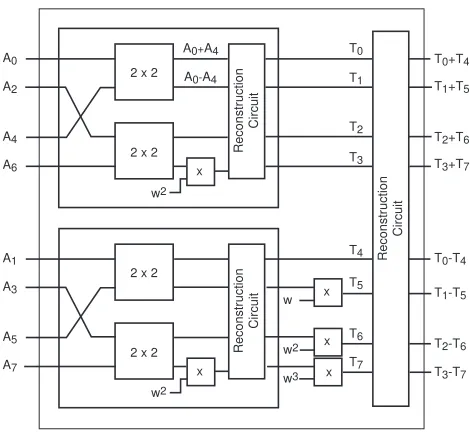
To achieve fast NTT operations, we utilize the Cooley–Tukey approach, as explained in Section 2.2. Cooley–Tukey approach works by splitting up the NTT–transform into two parts, performing the NTT operation on the smaller parts, and performing a final reconstruction to combine the results of the two half–size NTT transform results into a full–sized NTT operation. For the coefficients of NTT, we haveAi=
P32K−1
j=0 A2j·wi(2j)modp+wiP 32K−1
j=0 A2j+1·wi(2j)modpand denote this expression asAi=Ei+wiOi, whereEi andOi represent the ithcoefficients of the 32K NTT operation on the even and odd coefficients of the polynomial A(x), respectively. It is important to note that if the twiddle factor of the 64 K NTT operation is w, the twiddle factor of the smaller 32K operation will be w2. Because of the periodicity of the NTT operation, we know that Ei+32K = Ei and Oi+32K = Oi. Therefore, we have Ai = Ei+wiOi for 0 ≤i <32K and Ai =Ei−32K+wiOi−32K for 32K ≤i < 64K. For the twiddle factor, it holds that
wi+32K =wi·w32K =−wi. Consequently, we can achieve a full 64K NTT operation with two small 32K NTT operations utilizing the following reconstruction operation
Ai=Ei+wiOi,
Ai+32K =Ei−wiOi. (1)
The reconstruction operation is performed iteratively over very large number of coefficients. An 8×8 NTT circuit is illustrated in Figure 1. Note that, in a full 64K NTT circuit, the twiddle factorw16484is used in 8×8 NTT circuits.
Coefficient Multiplication and Accumulation Since our target FPGA has multiple number of DSP units and Block RAMs, we are able to parallelize the multiplication and accumulation operations at each level of the iterative NTT operation. We can utilize 3·KDSP units to achieveK modular multiplications in parallel, with a 4–cycle throughput, whereKis a design parameter that depends on the number of available DSP units in the target architecture. In our design,Kis chosen as a power of 2.
To be able to feed the DSP units with correct polynomial coefficients during multiplication cycles, we utilizeK separate Block RAMs (BRAM)) to store the polynomial coefficients. The algorithm used to access the polynomial coefficients in parallel is described in Algorithm 4. The algorithm takes the BRAM content (i.e., the coefficients ofA(x)), the degreeN = 2n, the current levelm, and the number of modular multipliers
K = 2κ as input, and generates the indexes in a parallel manner. Every four clock cycles, we try to feed modular multipliers the number of coefficients which is as close toK as possible. Ideally, it is desirable to perform exactlyKmodular multiplications in parallel, which is not possible due to the access pattern to the powers ofw. Algorithm 4, on the other hand, achieves a good utilization of modular multiplication units.
ALGORITHM 4:Parallel access to polynomial coefficients
input :A(x) =A0+A1x+. . .+A2N−1x2N−1,n,m, andκ < n output:Bi[j]
1 mCnt←2m−1−1 ; /* number of multiplications in a block */
2 bSize←2m; /* size of a block */
3 BRAM Cnt←2κ−2 ; /* number of BRAMs */
4 if bSize≤2κ−2 then fort= 0to 1024 do
fori= 0 to BRAM Cntdo in parallel forj=i+bSize−mCntto i+bSizedo
fork= 0 to 3do
5 AccessBRAMj[t+ 2k] ; 6 AccessBRAMj[t+ 2k+ 1] ;
k←k+ 1; end
j←j+ 1; end
i←i+bSize; end
t←t+ 8; end
end 7 else
fori= 0to BRAM Cntdo in parallel forj= 0 to 1024do
fork= 2m−κ+1to 2m−κ+2do 8 AccessBRAMi[k+j] ;
k←k+ 1; end
j←j+ 2m−κ+2; end
i←i+ 1; end
2 x 2
T4
2 x 2 Reconstr
uction Circuit T1 T7 T3 A0 A2 A4
A6 x
2 x 2
T0
2 x 2 Reconstr
uction Circuit T6 T2 T5 A1 A3 A5 A7
T0+T4
T1+T5
T0-T4
T1-T5
x x x w3 w2 x w Reconstr uction Circuit w2 w2
T2+T6
T3+T7
T2-T6
T3-T7
A0+A4
A0-A4
Fig. 1.Construction of the 8×8 NTT circuit iteratively.
4th coefficient of the polynomial with w2 = w16384. Since the coefficients are perfectly dispersed, we can read 256 coefficients to feed the 256 multipliers in four clock cycles. This is perfect as the throughput of our multipliers are also four cycles. When the multiplication operations are complete, with an offset of 19 cycles (four clock cycles are for the warm up of the pipeline whereas 15 clock cycles are the tail cycles necessary in a pipelined design to finish the last operation), the results are written back to the same address of the RAM block as the one the coefficients are read from. Since we are utilizing dual port RAM structures, and we guarantee different read and write addresses on each block, collisions never occur with this organization. We provide formulae for the number of multiplications in each level and an estimate of the number of clock cycles needed for their computation in our architecture. Suppose N = 2n and K = 2κ (n > κ) are the number of coefficients in our polynomial and the number of modulo multipliers in our target device, respectively. The coefficients are stored in block RAMS (BRAMs), with a word size of 32 bits and an address length of 10 bits (1024 coefficients per BRAM). For ideal case, the number of modular multipliers should be 4 times the number of BRAMS required to store a single polynomial. The formula for the number of multiplications for the levelm >1 can be given asM= 2n+1−m·(2m−1−1).Also, usingK= 2κmultipliers, the number of clock cycles to compute all multiplications in a given level 1< m≤n+ 1 can be formulated as
CCm=
4 + 4·
M
α· bK/αc
+ 15 κ≥m
4 + 4·(Kβ + 1)·2n+1−m+ 15 κ < m,
whereα= 2κ−m·(2m−1−1) andβ= 2m−1−2κ. In the formula, the first (4) and the last terms (15) account for the warm up and the tail cycles.
when m = 3, we have to read every 6th, 7th and 8th out of every 8 coefficients. We can read 24·2 = 48 coefficients every clock cycle from the BRAMs. This means we can only utilize 192 out of 25 modular multipliers since the irregularity of the access to the polynomial coefficients. This, naturally, results in a slightly low utilization. However, since we can read 2 coefficients from each BRAM every clock cycle, we are at almost perfect utilization, resulting in 4 + 128·4 + 15 = 531 clock cycles for this and the rest of the stages. Since the operands of the both operations are accessed in a regular manner, the number of clock cycles spent on modular additions and subtractions are calculated as 2n+12·(τn+1), when there are 2
τ modular adders
and 2τ modular subtractors.
Reconstruction Once we are done with the multiplications, we utilize 64 modular adders and 64 modular subtractors to realize the addition and subtraction operations as shown in Equation 1.
4.2 Inner Multiplication
Inner multiplication of two 64Kpolynomials is trivial for our hardware design. We can load 256 coefficients from each polynomial every 4 cycles and feed the multipliers, without increasing the 4–cycle throughput. For a 64K polynomial inner multiplication we spend 1024 + 15 = 1039 clock cycles.
4.3 Inverse NTT
The Inverse NTT operation is identical to the NTT operation, except that instead of the twiddle factor
w, we use the twiddle factor wi = w−1modp. The precomputed twiddle factors of the inverse NTT are stored in the same block RAMs as the forward NTT twiddle factors, with an address offset. Therefore, the same control block can be utilized with a simple address change for thew coefficients for the inverse NTT operation.
4.4 Final Scaling
Final scaling is similar to the inner multiplication phase. We load each coefficient of the resulting polynomial, and multiply them with the precomputed scaling factor. Similar to the inner multiplication phase, we can load 256 coefficients from the resulting polynomial in 4 cycles cycle and feed the multipliers, without increasing the 4–cycle throughput. For a 64K polynomial final scaling operation, we spend 1039 clock cycles.
5
Implementation Results
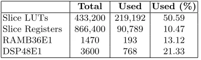
We developed the architecture described in the previous section into Verilog modules and synthesized it using Xilinx ISE and Vivado tools for the Virtex 7 XC7VX690T FPGA family. The synthesis results are summarized in Table 2. We synthesized the design and achieved an operating frequency of 250 MHz for multiplication of polynomials of degreen= 32,768 with a small word size of logp= 32 bit. The FPGA multiplier is used to process each component of the CRT representation of our large coefficient ciphertexts with logq= 1271 bits. In fact we keep all ciphertexts in CRT representation and only compute the polynomial form when absolutely necessary, e.g. for parity correction during modulus switching and before relinearization. We assume any data sent from the PC through the PCIe interface to the FPGA is stored in onboard BRAM units.
CRT Computation Cost. To facilitate efficient computation of multiplication and relinearization oper-ations we use a series of equal sized prime numbers to construct a CRT conversion. In fact, we chose the primes pis such that q=Ql
Table 2.Virtex-7 XC7VX690T device utilization of the multiplier
Total Used Used (%) Slice LUTs 433,200 219,192 50.59 Slice Registers 866,400 90,789 10.47 RAMB36E1 1470 193 13.12 DSP48E1 3600 768 21.33
– Precompute and storetk= 264·k (modpi) wherek∈[0,dlog(q/64)−1e].
– Given a coefficient ofc, we divide it into 64-bit blocks asc={. . . , wk, . . . , w0}.
– We compute the CRT result by evaluatingPt
k·wk (modpi) iteratively.
The CRT computation cost for 41 primespiper ciphertext polynomial is in the order of 89 msec on the CPU. The CRT inverse is similarly computed (with the addition of a word carry) before each modulus switching operation at essentially the same cost. Note that this high latency is a significant contributor of our choice to keep the operands in the CRT representation.
Communication Cost.The PCIe bus is only used for transactions of input/output values, NTT constants and transport of evaluation keys to the FPGA board. With 8 lanes each capable of supporting 8 Gbit/sec transport speed the PCIe is capable to transmit a 5 MB ciphertext in about 0.65 msec. Note that the NTT parameters used during multiplication also need to be transported since we do not have enough room in the BRAM components to keep them permanently. We have two cases to consider:
– Multiplication: We transport two polynomials of 5 MB each along with the NTT parameters of 5 MB and receive a polynomial of 10 MB, which costs about 3.25 msec per multiplication.
– Relinearization: We need to transport the ciphertext we want to relinearize, the NTT parameters and a set of log(q)/16≈80 evaluation keys (ciphertexts), where a window size of 16-bit is used, resulting in a 52 msec delay.
Multiplication Cost.We compute the product of two polynomials with coefficients of size log(p) = 32 bits using 256 modular multipliers in 12720 cycles, which translates to 152µsec. This figure is comprised of two NTT and one inverse NTT operations and one inner product computation. The addition of I/O transactions will increase the timing by 79µsec. Using the multiplication time, we estimate the latency of large polynomial multiplication with the following breakdown:
– Cost of small coefficient polynomial multiplications 41·152µsec = 6.25 msec.
– The PCIe transaction of the two input polynomials, the NTT coefficients and the double sized output polynomial is 3.25 msec.
Thus, the total latency for large polynomial multiplication in the CRT representation is computed in 9.51 msec.
Polynomial Modular Reduction. Since all operations are computed in a polynomial ring with a char-acteristic polynomial as modulus without any special structure, we use Barrett’s reduction technique to perform the reductions. Note that precomputing the constant polynomialx2N/Φ(x) (truncated division) in the CRT representation we do not need to compute any CRT or inverse CRT operations during modular reduction. Thus we can compute the reduction using two product operations in about 19 msec.
Modulus Switching. We realize the modulus switching operation by dropping the last CRT coefficient followed by parity correction. To compute the parity of the cut polynomial we need to compute an inverse CRT operation. The following parity matching and correction step takes negligible time. Note that the parities are single bit and therefore we do not need to compute another CRT operation. Therefore, modulus switching can be realized using one inverse CRT computation in 89 msec.
– We need to convert the ciphertext polynomial coefficients into integer representation using one inverse CRT operation, which takes 89 msec.
– The evaluation keys are kept in NTT representation, therefore we only need to compute two NTT operations for one operand and the result. For l = 41 primes and log(q)/16 ≈ 80 products the NTT operations take 331 msec.
– We need to transport the ciphertext, the NTT parameters and 80 evaluation keys (ciphertexts) resulting in a 52 msec delay.
– The summation of the partial products takes negligible time compared to the multiplications and the PCIe communication cost.
Then, the total relinearization operation takes 526 msec.
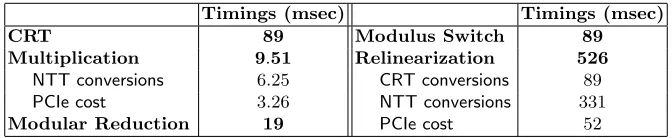
With the current implementation, the actual NTT computations still dominate over the other sources of latency such as PCIe communication latency and the CRT computations. However, if the design is further optimized, e.g. by increasing the number of processing units on the FPGA or by building custom support for CRT operations on the FPGA, then the PCIe communication overhead will become more dominant. The timing results are summarized in Table 3.
Table 3.Primitive operation timings including I/O transactions.
Timings (msec) Timings (msec)
CRT 89 Modulus Switch 89
Multiplication 9.51 Relinearization 526
NTT conversions 6.25 CRT conversions 89 PCIe cost 3.26 NTT conversions 331
Modular Reduction 19 PCIe cost 52
6
Comparison
To understand the improvement gained by adding custom hardware support in leveled homomorphic eval-uation of a deep circuit, weestimate the homomorphic evaluation time for the AES circuit and compare it with a similar software implementation by Dor¨oz et al [16].
Homomorphic AES evaluation.Using the NTRU primitives we implemented the depth 40 AES circuit following the approach in [16]. The tower field based AES SBox evaluation is completed using 18 Relin-earization operations and thus 2,880 RelinRelin-earizations are needed for the full AES. The AES circuit evalua-tion requires 5760 modular multiplicaevalua-tions. During the evaluaevalua-tion we also compute 6080 modulus switching operations. This results in a total AES evaluation time of 15 minutes. Note that during the homomorphic evaluation with each new level the operands shrink linearly with the levels thereby increasing the speed. We conservatively account for this effect by dividing the evaluation time by half. With 2048 message slots, the amortized per block AES evaluation time becomes 439 msec.
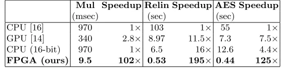
Table 4.Comparison of multiplication, relinearization times and AES estimate
Mul Speedup Relin Speedup AES Speedup
(msec) (sec) (sec)
CPU [16] 970 1× 10³ 1× 55 1×
GPU [14] 340 2.8× 8.97 11.5× 7.3 7.5× CPU (16-bit) 970 1× 6.5 16× 12.6 4.4× FPGA (ours) 9.5 102× 0.53 195× 0.44 125×
7
Conclusions
In this work we presented a custom hardware design to address the performance bottleneck in leveled somewhat homomorphic encryption evaluations. Given the large parameters used in such systems we design a large NTT based multiplier capable of multiplying very large degree polynomials. With the implementation of a CRT representation on the coefficients we managed to build a custom core capable of supporting polynomial multiplications with very large degree and very large coefficient polynomials. The design is highly optimized using numerous techniques to speedup the NTT computations, and to reduce the burden on the PC/FPGA interface. The resulting architecture dramatically improves the modular multiplication and relinearization speeds of the LTV SWHE scheme over a comparable software implementations. To demonstrate the effectiveness of the accelerator, we estimated the homomorphic AES evaluation performance and determined a speedup of about 28 times. Finally, we would like to note that the AES estimate is only to get a sense of the improvement, and in practice such a custom accelerator architecture may prove useful in more practical homomorphic evaluation applications.
References
1. Agarwal, R.C., Burrus, C.S.: Fast convolution using fermat number transforms with applications to digital filter-ing. Acoustics, Speech and Signal Processing, IEEE Transactions on 22(2), 87–97 (Apr 1974)
2. Aysu, A., Patterson, C., Schaumont, P.: Low-cost and area-efficient fpga implementations of lattice-based cryp-tography. In: HOST. pp. 81–86. IEEE (2013)
3. Barrett, P.: Implementing the rivest shamir and adleman public key encryption algorithm on a standard digital signal processor. In: Odlyzko, A. (ed.) Advances in Cryptology CRYPTO 86, Lecture Notes in Computer Science, vol. 263, pp. 311–323. Springer Berlin Heidelberg (1987),http://dx.doi.org/10.1007/3-540-47721-7_24
4. Brakerski, Z., Gentry, C., Halevi, S.: Packed ciphertexts in LWE-based homomorphic encryption. IACR Cryp-tology ePrint Archive 2012, 565 (2012)
5. Brakerski, Z., Gentry, C., Vaikuntanathan, V.: Fully homomorphic encryption without bootstrapping. Electronic Colloquium on Computational Complexity (ECCC) 18, 111 (2011)
6. Brakerski, Z., Vaikuntanathan, V.: Efficient fully homomorphic encryption from (standard) LWE. In: FOCS. pp. 97–106 (2011)
7. Cao, X., Moore, C., O’Neill, M., Hanley, N., O’Sullivan, E.: Accelerating fully homomorphic encryption over the integers with super-size hardware multiplier and modular reduction. Under Review (2013)
8. Cooley, J.W., Tukey, J.W.: An algorithm for the machine calculation of complex fourier series. Math. comput 19(90), 297–301 (1965)
9. Coron, J.S., Lepoint, T., Tibouchi, M.: Batch fully homomorphic encryption over the integers. IACR Cryptology ePrint Archive 2013, 36 (2013)
10. Coron, J.S., Mandal, A., Naccache, D., Tibouchi, M.: Fully homomorphic encryption over the integers with shorter public keys. In: CRYPTO. pp. 487–504 (2011)
11. Coron, J.S., Naccache, D., Tibouchi, M.: Public key compression and modulus switching for fully homomorphic encryption over the integers. In: EUROCRYPT. pp. 446–464 (2012)
12. Cousins, D., Rohloff, K., Schantz, R., Peikert, C.: SIPHER: Scalable implementation of primitives for homomor-phic encrytion. Internet Source (September 2011)
14. Dai, W., Dor¨oz, Y., Sunar, B.: Accelerating ntru based homomorphic encryption using gpus. In: HPEC (2014) 15. van Dijk, M., Gentry, C., Halevi, S., Vaikuntanathan, V.: Fully homomorphic encryption over the integers. In:
EUROCRYPT. pp. 24–43 (2010)
16. Dor¨oz, Y., Hu, Y., Sunar, B.: Homomorphic aes evaluation using ntru (2014),https://eprint.iacr.org/2014/ 039.pdf, iACR ePrint Archive
17. Dor¨oz, Y., ¨Ozt¨urk, E., Sunar, B.: Evaluating the hardware performance of a million-bit multiplier. In: Digital System Design (DSD), 2013 16th Euromicro Conference on (2013)
18. Dor¨oz, Y., Ozt¨¨ urk, E., Sunar, B.: Accelerating fully homomorphic encryption in hardware (2014), http://ecewp.ece.wpi.edu/wordpress/vernam/files/2013/09/ Accelerating-Fully-Homomorphic-Encryption-in-Hardware.pdf, to appear IEEE Transactions on Com-puters
19. Gentry, C.: A Fully Homomorphic Encryption Scheme. Ph.D. thesis, Stanford University (2009) 20. Gentry, C.: Fully homomorphic encryption using ideal lattices. In: STOC. pp. 169–178 (2009)
21. Gentry, C., Halevi, S.: Fully homomorphic encryption without squashing using depth-3 arithmetic circuits. IACR Cryptology ePrint Archive 2011, 279 (2011)
22. Gentry, C., Halevi, S.: Implementing Gentry’s fully-homomorphic encryption scheme. In: EUROCRYPT. pp. 129–148 (2011)
23. Gentry, C., Halevi, S., Smart, N.P.: Better bootstrapping in fully homomorphic encryption. IACR Cryptology ePrint Archive 2011/680 2011 (2011)
24. Gentry, C., Halevi, S., Smart, N.P.: Fully homomorphic encryption with polylog overhead. IACR Cryptology ePrint Archive Report 2011/566 (2011),http://eprint.iacr.org/
25. Gentry, C., Halevi, S., Smart, N.P.: Homomorphic evaluation of the AES circuit. IACR Cryptology ePrint Archive 2012 (2012)
26. Karatsuba, A., Ofman, Y.: Multiplication of many-digital numbers by automatic computers. Doklady Akad. Nauk SSSR 145(293–294), 85 (1962)
27. L´opez-Alt, A., Tromer, E., Vaikuntanathan, V.: On-the-fly multiparty computation on the cloud via multikey fully homomorphic encryption. In: STOC (2012)
28. Montgomery, P.L.: Modular multiplication without trial division. Mathematics of Computation 44(170), 519–521 (April 1985)
29. Moore, C., Hanley, N., McAllister, J., O’Neill, M., O’Sullivan, E., Cao, X.: Targeting FPGA DSP slices for a large integer multiplier for integer based FHE. Workshop on Applied Homomorphic Cryptography 7862 (2013) 30. P¨oppelmann, T., G¨uneysu, T.: Towards efficient arithmetic for lattice-based cryptography on reconfigurable
hardware. In: Hevia, A., Neven, G. (eds.) LATINCRYPT. Lecture Notes in Computer Science, vol. 7533, pp. 139–158. Springer (2012)
31. Rohloff, K., Cousins, D.: A scalable implementation of somewhat homomorphic encryption built on ntru. In: 2nd Workshop on Applied Homomorphic Cryptography (WAHC’14) (2014)
32. Smart, N.P., Vercauteren, F.: Fully homomorphic encryption with relatively small key and ciphertext sizes. In: Public Key Cryptography. pp. 420–443 (2010)
33. Smart, N.P., Vercauteren, F.: Fully homomorphic SIMD operations. IACR Cryptology ePrint Archive 2011, 133 (2011)
34. Stehl´e, D., Steinfeld, R.: Making ntru as secure as worst-case problems over ideal lattices. Advances in Cryptology – EUROCRYPT ’11 pp. 27–4 (2011)
35. Wang, W., Hu, Y., Chen, L., Huang, X., Sunar, B.: Accelerating fully homomorphic encryption using GPU. In: HPEC. pp. 1–5 (2012)
36. Wang, W., Hu, Y., Chen, L., Huang, X., Sunar, B.: Exploring the feasibility of fully homomorphic encryption. IEEE Transactions on Computers 99(PrePrints), 1 (2013)