SMART: An Efficient, Scalable, and Robust
Streaming Video System
Feng Wu
Microsoft Research Asia, 3F Sigma Center, No. 49 Zhichun Road, Haidian, Beijing 100080, China Email:[email protected]
Honghui Sun
Microsoft Research Asia, 3F Sigma Center, No. 49 Zhichun Road, Haidian, Beijing 100080, China Email:[email protected]
Guobin Shen
Microsoft Research Asia, 3F Sigma Center, No. 49 Zhichun Road, Haidian, Beijing 100080, China Email:[email protected]
Shipeng Li
Microsoft Research Asia, 3F Sigma Center, No. 49 Zhichun Road, Haidian, Beijing 100080, China Email:[email protected]
Ya-Qin Zhang
Microsoft Research Asia, 3F Sigma Center, No. 49 Zhichun Road, Haidian, Beijing 100080, China Email:[email protected]
Bruce Lin
Microsoft Corporation, One Microsoft Way, Redmond, WA 98052-6399, USA Email:[email protected]
Ming-Chieh Lee
Microsoft Corporation, One Microsoft Way, Redmond, WA 98052-6399, USA Email:[email protected]
Received 9 December 2002; Revised 12 September 2003
SMART, the acronym ofscalable media adaptation and robust transport, is a suite of compression and transmission technologies for efficient, scalable, adaptive, and robust video streaming over the best-effort Internet. It consists of two indispensable parts: SMART video coding and SMART video streaming. The SMART video coding part is an efficient DCT-based universal fine gran-ularity scalable coding scheme. Since the SMART video coding scheme adopts multiple-loop prediction and drifting reduction techniques at the macroblock level, it can achieve high coding efficiency at a wide range of bit rates. More importantly, it provides all sorts of scalabilities, that is, quality, temporal, spatial, and complexity scalabilities, in order to accommodate heterogeneous time-variant networks and different devices. The SMART video streaming part is a transport scheme that fully takes advantages of the special features of the scalable bitstreams. An accurate bandwidth estimation method is first discussed as the prerequi-site of network adaptation. Then, flexible error resilience technique and unequal error protection strategy are investigated to enhance the robustness of streaming SMART bitstream. The SMART system shows excellent performances with regard to high coding efficiency, flexible channel bandwidth adaptation, smooth playback, and superior error robustness in static and dynamic experiments.
1. INTRODUCTION
With the recent developments in computing technology, compression and transmission technologies, high-capacity storage devices, and high-speed wired and wireless networks, more and more users expect to enjoy high-quality
multime-dia services over the Internet [1,2,3]. In general, there are
two approaches to provide multimedia services on demand:
offline downloadingandonline streaming. Since the streaming approach enables users to experience a multimedia presenta-tion on the fly while it is being downloaded from the Inter-net, it has prevailed in both the academia and the industry. In virtue of the streaming techniques, users no longer have
to suffer from long and even unacceptable transport time for
full download.
Figure 1exemplifies a typical scenario for streaming the same content to users. Raw video sequences are usually com-pressed in advance and then saved in the storage device. Upon the client’s request, the streaming server retrieves com-pressed bitstream from the storage device and delivers it through the Internet that consists of many heterogeneous
subnetworks. Receivers may use different devices for
decod-ing, presenting the received video data at different
resolu-tions, different frame rates, and different qualities depending
on their connection speeds and device capabilities.
In fact, such multimedia streaming services create sev-eral challenges which may lie in technical fields even beyond video compression. These challenges mainly include but are not limited to the following.
(1)Contents
Multimedia contents are huge and growing rapidly. For ex-ample, only from RealNetworks Company’s statistics in 2001
[4], over 350 000 hours of live sports, music, news, and
en-tertainment contents were transmitted over the Internet ev-ery week. Furthermore, there are several hundred thousand
hours of contents available on demand. To efficiently and
ef-fectively deliver such huge multimedia contents, advanced compression and transmission technologies are crucial.
(2)Networks
The networks used to deliver multimedia contents are be-coming more and more complicated and heterogeneous. Ad-ditionally, unlike traditional dedicated networks, since the
general best-effort Internet lacks quality of service (QOS)
guarantee, network conditions themselves may be changing from time to time. This requires that compressed
multime-dia contents are deliverable over different networks from
nar-rowband to broadband and from wired to wireless networks. It also requires that the delivery mechanism is able to adapt to network variations while providing a consistent user ex-perience. In addition, since packet loss or channel error is inevitable during transmission, advanced error control tech-nologies are required to protect the transmitted data.
(3)Devices
End-user devices are also becoming very different in
process-ing power, memory, display resolution, and bandwidth. This
requires tailoring multimedia contents and delivery schemes to best fit each device in order to provide the best possible multimedia user experience.
A straightforward solution would be to independently compress the same video sequence into many nonscalable bitstreams for every possible bit rate, frame rate, resolution, and device complexity. Actually, this solution has been exten-sively applied to most of the commercial streaming products, such as Windows Media Player system and Real Player
sys-tem [4,5]. When a video sequence is retrieved, the streaming
server chooses an appropriate version of bitstream according to actual connection speed and device capability, and then transmits it to the user.
Obviously, video streaming systems based on the non-scalable compression techniques have several problems in taking the above challenges. Firstly, nonscalable video bit-streams are not able to adapt to time-variant networks. Even though switching among multiple nonscalable bitstreams is allowed at some key frames that are either compressed with-out prediction or coded with an extra lossless coded switch-ing bitstream, such streamswitch-ing systems only provide coarse and sluggish capability in adapting to bandwidth variations due to limitation in both the number of bitstreams and the number of key frames. Some studies have tried to solve this problem by switching at a special predictive frame, for
example, S frame in [6], SP frame in [7], and SF frame
in [8], which can reduce switching overhead and provide
more switching points at the same cost. Secondly, nonscal-able video bitstream is very sensitive to transmitted errors because almost every bit in the bitstream is very important and indispensable for decoding a group of pictures (GOP).
On the other hand, the scalable media adaptation and robust transport (SMART) system proposed in this paper is based on scalable compression techniques and is able to
pro-vide efficient, adaptive, and robust video streaming over the
Internet. The core of the system is an efficient and universal
fine granularity scalable (FGS) video codec. It uses multiple versions of references with increasing quality to make motion
prediction more accurate for improved coding efficiency. At
the same time, a drifting reduction technique is proposed to prevent possible error propagation due to corrupted high-quality references. When the two techniques are applied at the macroblock level, the SMART system can achieve a good
trade-offbetween low drifting errors and high coding effi
-ciency. Besides efficient fine granularity quality scalability,
the SMART system supports efficient temporal and spatial
scalabilities by utilizing similar techniques. Furthermore, the fine granularity scalability on complexity is also achieved by adjusting the decoding resolution, frame rate, and bit rate. In fact, the SMART system provides a universal scalable cod-ing framework. For a sequence, the generated bitstreams can be served to a vast range of applications from low bit rate to high bit rate and from a PC device to a non-PC device with-out complicated transcoding.
CI S COSYSTEMS
CI SCOSYSTEM S
CI SCOSYSTEMS CISCOS YST EMS
CISCOS YST EMS CIS COSYST EM S
CI S COSYSTEMS CISCOSYST EM S
Receiver 2 Cable Digital TV
Access SW
Receiver 3
Laptop Gateway
Domain A
Domain B
Domain C Internet
Access SW
Ethernet Streaming
server
Receiver 1 Source
Desktop PC
Gateway
Wireless networks
Receiver 4 Mobile phone Figure1: An exemplified scenario for streaming video.
method. Afterward, the transmitted video bitstreams are truncated to a bit rate that fits well in the estimated chan-nel bandwidth. Since packet losses are inevitable in the gen-eral Internet, error control mechanism is a key component in this part. A flexible error resilience technique is proposed to adaptively enhance the robustness of SMART video bit-stream. In addition, the SMART system provides a layered bitstream structure with a more important base layer and less important enhancement layers. Forward error correction (FEC) and automatic retransmission request (ARQ) tech-niques are applied to the base layer so as to reduce packet loss ratio and retransmission delay.
The rest of this paper is arranged as follows. Section 2
gives a brief overview of the SMART system. The SMART
video coding techniques are discussed inSection 3.Section 4
introduces the channel estimation method used in the SMART system. The flexible error resilience technique and
unequal error protection are described inSection 5. The
ex-perimental results presented in Section 6 demonstrate the
advantages of the SMART system. Finally, Section 7
con-cludes this paper.
2. OVERVIEW OF THE SMART SYSTEM
This section gives an overview of the SMART coding and streaming system. At present, there are two modes for a
streaming server to deliver video data to users:multicastand
unicast. In the multicast mode, the server needs to send only one bitstream to a group of users, which is automatically
replicated to all group members [9, 10], but this requests
that the network has to be equipped with multicast-enable routers. In the unicast mode, the server delivers video bit-stream to each user individually. The connection conditions between the server and each user can be estimated and mon-itored during transmission.
Since many routes in the current Internet do not enable the multicast mode, the SMART system discussed in this
pa-per will focus on the unicast applications.Figure 2illustrates
the block diagram of the SMART system. Source video is first input into the SMART encoder module to generate a base layer bitstream and one or two enhancement layer bit-streams. Besides bitstreams, the SMART encoder generates a description file for each enhancement bitstream that con-tains all information for flexible error resilience and packe-tization. The detailed coding techniques will be discussed in
Section 3, and the description file is introduced inSection 5. If the SMART encoder is powerful enough for real-time com-pression, the generated bitstreams can be directly packed and delivered just as in the live streaming applications. For the on-demand streaming applications, both the generated bit-streams and description files are saved in the storage device for future retrieval.
When the user submits a request to the SMART
stream-ing server, like thereal-time streaming protocol(RTSP) [11],
the retrieved content, destination address, and user device capability are first transmitted by the transmission control protocol (TCP). After the control module in the SMART server receives the request, one user datagram protocol (UDP) connection is established immediately between the server and the user. Both the video data and the feedback from the SMART client are transmitted by this UDP connec-tion. At the same time, the control module informs the server to retrieve the requested content from the storage device.
In the initial stage, the SMART system does not know the current channel conditions between the server and the client. Thus the base layer bitstream is packed with the
real-time transport protocol(RTTP) [12] format using default channel parameters. At the same time, a prespecified FEC strategy is used in the base layer bitstream to generate par-ity packets. In general, since the base layer bit rate is very low in the SMART system, several seconds of source and parity
packets can be rapidly delivered to the client as prebuffering.
SMART system Source
SMART encoder
Real time Streaming
Storage Error
resilience Control Request
FEC Network
monitor
Feedback
Transport Data
Internet
Control flow Data flow User device
SMART decoder SMART client
Figure2: The block diagram of the SMART system.
real-time control protocol(RTCP) format [12] and sent back to the network monitor module in the SMART server. Ac-cordingly, the SMART server can estimate the current avail-able channel bandwidth.
With the obtained channel parameters, the SMART server starts to optimally pack the base layer and enhance-ment layer bitstreams with RTTP format. FEC protection depth to the base layer can be also adaptive to the channel conditions. In order to avoid network congestion, the ac-tual bandwidth for the enhancement layer is the remaining part of the estimated channel bandwidth after delivering the base layer and FEC packets. Since the enhancement layer bit-stream provides bit level scalability, it can be readily and pre-cisely truncated to fit in the given bandwidth. Consequently, the SMART system can fully utilize available channel band-width and provide the user with better quality. Packet loss ratio and latency are periodically sent back by the client. The SMART server can timely adjust data transmission according to the feedbacks and the estimated channel bandwidth.
In the SMART system, another important feedback from the client is the negative acknowledgement (NACK) to no-tify the SMART server in which base layer packets are lost during transmission. Since the base layer is still a nonscal-able bitstream, any lost packet would make the quality of the frames followed in the same GOP degrade rapidly. Therefore, the ARQ technique is also used to protect the base layer in the SMART system. Once the client detects lost packets at the base layer, a feedback is immediately sent out. The server will rapidly retransmit the lost packets. At the same time,
any ARQ request received by the server will affect the
send-ing rate to prevent further congestion in the channel. Since the base layer bit rate is very low in the SMART system, they can be strongly protected with small overhead bits. In addi-tion, SMART video coding also provides the enhancement layer with an inherent error recovery feature. Any lost packet does not cause obvious visual artifacts. Moreover, it can be gracefully recovered in the following frames. Therefore, the current SMART system does not have any protection to the enhancement layer bitstreams.
In the following sections, the key techniques used in the SMART system, such as SMART video coding, bandwidth es-timation, error resilience, and unequal error protection, will be discussed in detail.
3. SMART VIDEO CODING
How to efficiently compress video data with various
scala-bilities of rate, quality, temporal, spatial, and complexity is an active research topic in video coding field. Scalable video coding techniques have been developed rapidly in the past decade. Among them, spatial and temporal scalable
cod-ing techniques that provide video presentation at different
resolutions, and frame rates have been accepted in some main video coding standards such as MPEG-2, MPEG-4, and
H.263++ [13,14,15].
In addition, FGS video coding techniques have been ex-tensively studied in recent years. MPEG-4 standard already accepted the bit plane coding technique in the streaming
video profile (SVP) [16,17]. In MPEG-4 FGS, an encoder
using the motion-compensated discrete cosine transforma-tion (DCT) transform coding generates a base layer video as the lowest quality layer. The residue between the original image and the reconstructed base layer image forms the en-hancement layer with the bit plane coding technique, which provides an embedded bitstream and fine granularity quality and temporal scalabilities.
One major feature in MPEG-4 FGS is that the base layer and all the bit planes at the enhancement layer in a predicted frame are always compensated from the reconstructed ver-sion of the base layer in the reference. Therefore, it provides a remarkable capability in both bandwidth adaptation and er-ror recovery. By predicting the enhancement layer from the base layer, any bitstream truncation and lost packets at the
enhancement layer have no effect on the frames followed.
However, this also makes MPEG-4 FGS suffer from severe
degradation in coding efficiency due to the lowest quality
ref-erence. Furthermore, it is difficult for MPEG-4 FGS to
Base layer 1st bit plane 2nd bit plane 3rd bit plane 4th bit plane
1 2 3 4 5
Frames
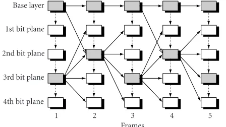
Figure3: The proposed multiple-loop prediction technique with two references case.
the coding efficiency at the enhancement layer would be
fur-ther degraded.
Therefore, the SMART video coding is proposed based
on our previous works [18,19]. The multiple-loop
predic-tion and drifting reducpredic-tion techniques are first used at the
quality enhancement layer to achieve a good trade-off
be-tween high coding efficiency and low drifting errors. Then,
these techniques are extended to the temporal and spatial
scalabilities, consequently, forming an efficient and universal
scalable video coding framework.
3.1. Multiple-loop prediction
The multiple-loop prediction technique was first proposed
in [18,19] to improve the coding efficiency of MPEG-4 FGS.
The basic idea is to use as many predictions from the en-hancement layer as possible instead of always using the base layer as in MPEG-4 FGS. Because the quality of a frame is higher at the enhancement layer than at the base layer, this will make motion prediction more accurate, thus
improv-ing the codimprov-ing efficiency. Considering the cost by
introduc-ing multiple references at the enhancement layer,Figure 3
il-lustrates a typical multiple-loop prediction scheme with one additional reference used in the enhancement layer coding.
InFigure 3, the gray rectangular boxes denote the recon-structed base layer or the reconrecon-structed enhancement layer at a certain bit plane as references for the next frame coding. Solid arrows with solid lines between two adjacent frames are for temporal prediction, solid arrows with dashed lines are for prediction in the transform domain, and hollow ar-rows with solid lines are for reconstruction of high-quality reference from the previous base layer. Each frame at the base layer is always predicted from the previous frame at the base
layer (low-quality reference) so as to avoid any effect from the
lost enhancement data. Each frame at the enhancement layer is predicted from the previous frame at the enhancement
layer (high-quality reference) for high coding efficiency.
In the FGS video coding schemes, the base layer bit rate is usually very low. It is reasonable to assume that the base layer bitstream can be completely transmitted to the client. Since the base layer is still predicted from the previous base layer, any bitstream truncation and lost packets at the
enhance-ment layer have no effect on the base layer video. However,
when those bit planes used to reconstruct the high-quality reference are truncated or corrupted during transmission, this would inevitably cause drifting errors at the enhance-ment layer. As a result, the decoded enhanceenhance-ment layer video may be deteriorated rapidly.
3.2. Drifting reduction
In order to effectively reduce drifting errors at the
enhance-ment layer, the basic idea is to make sure that the encoder and the decoder have the same reconstructed reference for any fu-ture frame prediction, although the reconstructed reference may not have the best quality it could get if reconstructed using the high-quality reference.
We will show this idea through an example inFigure 3.
In the decoder end, if the third bit plane in Frame 1 is trun-cated or dropped which is used in the encoder end to get the high-quality reference, the enhancement layer in Frame 2 will have to use the previous low-quality reference instead. Of course, some quality losses would be introduced by doing so. However, as long as in both the encoder end and the de-coder end the reconstruction of the high-quality reference of Frame 2 always uses the base layer of Frame 1 as the reference, then the errors in Frame 1 could not further propagate to any frames followed. In other words, the reference used for
pre-diction could be different from that used for reconstruction.
This feature will prevent the errors drifting and preserve all the bandwidth adaptation and error recovery features as in MPEG-4 FGS.
As shown by hollow arrows with solid lines inFigure 3,
some frames, such as Frames 2 and 4, reconstruct the high-quality references from the previous low-high-quality reference at both the encoder and the decoder to prevent the errors prop-agating into future frames. However, if the third bit plane of Frame 1 is available at the decoder end, a better second bit plane quality of Frame 2 can still be reconstructed from the high-quality reference for display purpose only. In other
words, the reconstruction of display image can be different
from that of reference image.
Although the proposed technique significantly reduces the drifting errors from the previous frames, it still has a
negative effect on coding efficiency because the high-quality
reference does not always get the best quality it could get. If the reference for prediction and reconstruction is chosen as frame-based, that is, all enhancement layer macroblocks in
a frame with the same reference, it is very difficult for the
SMART video coding to provide a good trade-offbetween
high coding efficiency and low drifting errors.
3.3. Macroblock-based mode selection
The technique choosing the proper reference for prediction and reconstruction at each enhancement layer macroblock
is first proposed in [20]. Derived from MPEG-4 FGS and
Low-quality reference
High-quality reference
Mode 1 Mode 2 Mode 3
Figure 4: Three intercoding modes for the quality enhancement layer.
enhancement layer. Gray rectangular boxes indicate those to be reconstructed as references. Solid arrows with solid lines between two adjacent frames are for temporal predictions, solid arrows with dashed lines are for prediction in the trans-form domain, and hollow arrows with solid lines are for reconstruction of high-quality reference from the previous base layer.
In Mode 1, the base layer and the enhancement layer are both predicted and reconstructed from the previous low-quality reference. Since the low-low-quality reference is always available at the decoder, there is no drifting error in this
mode. The coding efficiency of this mode is low due to
low-quality temporal prediction. If all enhancement layer mac-roblocks are encoded with this mode, the proposed scheme is similar to MPEG-4 FGS.
In Mode 2, the base layer is predicted and reconstructed from the previous low-quality reference, but the enhance-ment layer is predicted and reconstructed from the previ-ous high-quality reference. It can significantly improve the
coding efficiency at moderate and high bit rates. There is no
drifting error at the base layer. When the channel bandwidth is not high enough to transmit the high-quality reference, this mode would cause drifting errors at the enhancement layer.
In Mode 3, the enhancement layer is predicted from the previous high-quality reference while reconstructed from the previous low-quality reference at both the encoder and the decoder. This mode was for the purpose of drifting reduc-tion. Since the low-quality reference is always consistent at both the encoder and the decoder, the drifting errors prop-agated from previous high-quality references can be elimi-nated with Mode 3.
More intercoding modes could be readily added in the SMART coding as long as they have the virtue in
improv-ing codimprov-ing efficiency or reducing error propagation. In
or-der to achieve a good trade-offbetween low drifting errors
and high coding efficiency, a mode selection algorithm is
proposed to choose the proper coding mode for each mac-roblock. Besides the above three intermodes, intramode is al-lowed in the enhancement layer coding. Intramode or inter-mode is determined by motion estimation. If a macroblock is encoded with the intramode at the base layer, the cor-responding enhancement macroblock is also encoded with the intramode without temporal prediction. If a macroblock at the base layer is encoded with temporal prediction, the
proposed mode selection algorithm has to determine which intercoding mode should be used at the corresponding en-hancement macroblock.
The reference for prediction in Mode 1 is of low quality but the reference used in Mode 2 and Mode 3 is of high qual-ity. If the absolute mean of the predicted DCT residues pro-duced in Mode 1 is less than that in Modes 2 and 3, the cur-rent macroblock is coded using Mode 1; otherwise, the mode selection algorithm further determines the coding mode be-tween Mode 2 and Mode 3. Both Modes 2 and 3 are predicted
from the high-quality reference, the difference between them
lies in the reference for reconstruction. In general, most of the enhancement macroblocks should be coded with Mode
2 for high coding efficiency. Mode 3 is used only when the
drifting errors are more than a given threshold. In order to estimate the potential drifting errors at the encoder, the
iter-ative drifting model proposed in [21] is given as follows:
y(n)=
DCT1denote motion compensation and IDCT, respectively,
y(n−1) is the accumulative error propagated to the (n−1)th
frame, andX(n−1) is DCT coefficients encoded in those
bit planes for reconstruction of the high-quality reference in
the (n−1)th frame. With motion compensation, their sum
forms the next drifting errors in the nth frame. If the
es-timated drifting error y(n) is more than the given
thresh-old, this macroblock is encoded with Mode 3; otherwise, this macroblock is encoded with Mode 2.
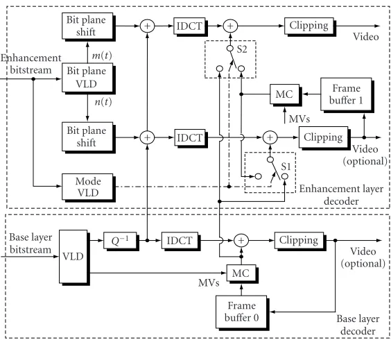
For the convenience of a better understanding of the proposed multiple-loop prediction, drifting reduction, and
macroblock-based mode selection,Figure 5illustrates an
ex-emplified block diagram of the SMART decoder with quality scalability. There are two reference frames in the decoder. The first one is located in the base layer decoder and stored in the
frame buffer 0 as a low-quality reference, while the second
one is located in the enhancement layer decoder and stored
in the frame buffer as a high-quality reference.
Only the low-quality reference is allowed in the recon-struction of the base layer in order to assure that no drift-ing error exists at this layer. The enhancement layer can use
two different quality references for reconstruction. The
en-hancement bitstream is first decoded using bit plane variable length decoding (VLD) and mode VLD. The bit planes at the enhancement layer are categorized into a lower enhancement layer and a higher enhancement layer. Only the bit planes at the lower enhancement layer are used to reconstruct the
high-quality reference. InFigure 5,n(t) is the number of bit
planes at the lower enhancement layer andm(t) is the
num-ber of additional bit planes for the reconstruction of the dis-play frame.
The decoded block-based bit planes are used to
recon-struct the DCT coefficients of the lower and higher
Bit plane
shift + IDCT + Clipping Video
S2 Enhancement
bitstream Bit plane VLD
m(t)
n(t) Bit plane
shift + IDCT
Mode VLD
MC buFrameffer 1 MVs
+ Clipping Video (optional) S1
Enhancement layer decoder Base layer
bitstream VLD
Q−1 IDCT + Clipping
Video (optional) MVs MC
Frame
buffer 0 Base layer decoder Figure5: The exemplified SMART decoder with quality scalability.
DCT, the lower enhancement DCT coefficients plus the
re-constructed base layer DCT coefficients generate the error
image for reference, and all DCT coefficients including the
higher enhancement layer generate the error image for dis-play. Furthermore, there are two switches S1 and S2 at the SMART decoder that control which temporal prediction is used at each enhancement macroblock. The decoded mac-roblock coding mode decides the actions of the two switches. When one macroblock is coded as Mode 1, the switches S1 and S2 connect to the low-quality prediction. When it is coded as Mode 2, both of the switches S1 and S2 connect to the high-quality prediction. When it is coded as Mode 3, the switch S1 connects to the low-quality prediction. How-ever, the switch S2 still connects to the high-quality predic-tion. Since the display frame does not cause any error prop-agation, the display frame is always reconstructed from the high-quality prediction in Mode 3.
3.4. Universal scalable coding framework
The techniques discussed in Sections3.1,3.2, and3.3can be
readily extended to the temporal and spatial scalable video coding. The basic idea is to use more than one enhance-ment layer based on a common base layer to impleenhance-ment fine granularity quality, temporal, and spatial scalabilities within the same framework. In order to achieve high coding ef-ficiency for various scalabilities, multiple prediction loops
with different quality references are employed in the
pro-posed framework. For example, by utilizing the high-quality reference in the spatial enhancement layer coding, the
pro-posed framework can likewise fulfill efficient spatial
scala-bility. The complexity scalability is inseparable with other scalabilities in the SMART codec. It is achieved by increas-ing/decreasing the bit rate, frame rate, and resolution. The
changes in the frame rate and resolution provide coarse scal-ability on complexity. Because of the property of fine gran-ularity of each layer on bit rate, the SMART codec also provides fine scalability on complexity by adjusting the bit rate of each layer. The lowest complexity bound is the
low-resolution base layer decoding, which should be sufficiently
low for many applications.
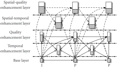
Figure 6illustrates the proposed universal scalable cod-ing framework. Source video with two resolutions is com-pressed in the proposed framework. Narrow rectangles de-note low-resolution video and wide rectangles dede-note
high-resolution video. There are two different enhancement layers
sharing a common base layer, and two optional enhancement ones. The bottom layer is the base layer. It is usually gener-ated as the lowest quality, lowest resolution, least smooth-ness, and least complexity. The quality enhancement layer compresses the same resolution video as that at the base layer. It will improve the decoded quality of the base layer. The tem-poral enhancement layer improves the base layer frame rate and makes the decoded video look smooth. The rest two en-hancement layers improve the video quality and frame rate at high resolution. These two enhancement layers are optional in the proposed framework and appear only if the video with
two different resolutions is encoded. The same resolution
en-hancement layers are stored in the same bitstream file. There-fore, the SMART coding scheme generates at most three bit-streams: one base layer bitstream and two enhancement layer bitstreams.
Spatial-quality enhancement layer
Spatial-temporal enhancement layer
Quality enhancement layer
Temporal enhancement layer
Base layer
I P P
Figure6: The proposed SMART coding framework.
Figure 6, each rectangle denotes the whole frame bitstream at one enhancement layer. The shadow region is the actual transmitted part, whereas the blank region is the truncated part. Hence the proposed SMART video coding provides the most flexible bit rate scalability.
Since the multiple-loop prediction technique is used in the proposed framework, every layer, excluding the base
layer, can select the prediction from two different references.
As shown by solid arrows with solid lines in Figure 6, the
quality enhancement layer use the reconstructed base layer and the reconstructed quality enhancement layer at a cer-tain bit plane as references. As shown by hollow arrows with solid lines, the temporal enhancement layer is bidirectionally predicted from the base layer and the quality enhancement layer. The predictions for the two high-resolution enhance-ment layers are denoted by solid arrows with dashed lines and hollow arrows with dashed lines, respectively.
Similarly, some intercoding modes are defined at the temporal and spatial enhancement layers, which can be
found in [22,23,24]. Each coding mode has its unique
ref-erences for prediction and reconstruction. The similar mode
selection algorithm discussed inSection 3.3can be also
ap-plied to the temporal and spatial enhancement layers. In fact,
some other techniques proposed in [25,26,27,28] can be
easily incorporated into the framework by defining several new coding modes.
4. CHANNEL ESTIMATION
In the streaming applications, one important component is congestion control. Congestion control mechanisms usually contain two aspects: estimating channel bandwidth and reg-ulating the rate of transmitted bitstream. Since the SMART video coding provides a set of embedded and full scalable bitstreams, rate regulation in the SMART system is essen-tially equal to truncating bitstreams to a given bit rate. There is not any complicated transcoding needed. The remaining problem is how to estimate the channel bandwidth.
Typically, channel estimation techniques are divided into two categories: based and model-based. The probe-based techniques estimate the channel bandwidth bottleneck by adjusting the sending rate in a way that could maintain
packet loss ratio below a certain threshold [29]. The
model-based techniques are model-based on a TCP throughput model that explicitly estimates the sending rate as a function of recent packet loss ratio and latency. Specifically, the TCP
through-put model is given by the following formula [30]:
λ=1.22×MTU
RTT×√p , (2)
where λ is the throughput of a TCP connection (in B/s),
MTU is the packet size used by the connection (in bytes), RTT is the round-trip time of the connection (in seconds),
andpis the packet loss ratio of the connection.
With formula (2), the server can estimate the available
bandwidth by receiving feedback parameters RTT and p
from the client.
Among all existing model-based approaches,
TCP-friendly rate control (TCP-FRC) [31] is the most deployable
and successful one. The sending rate formula, by considering the influence of time out, is given as follows:
λ= MTU
RTT2p/3 + RTO33p/8p1 + 32p2, (3)
where RTO is the TCP retransmission time-out value (in sec-onds).
However, TCP-FRC has one obvious drawback undesir-able for the SMART system, that is, the estimated bandwidth always fluctuates periodically even if the channel bandwidth is very stable. The reason is that TCP-FRC is trying to in-crease the sending rate when there is no lost packet. This un-fortunately leads to a short-term congestion. Since TCP-FRC is very sensitive in the low packet loss ratio case, the sending rate is greatly reduced again to avoid further congestion.
Therefore, the SMART system adopts a hybrid model-based and probe-model-based method to estimate the available channel bandwidth. TCP-FRC is first used to calculate an initial estimated bandwidth by packet loss ratio and RTT. If there is no lost packet, the estimated bandwidth should be more than the previous estimation. On the other hand, some packets that contain less important enhancement data are transmitted with the probing method. This is a feature of the SMART bitstream. Even though those packets are lost
for probing, they do not affect other data packets. In general,
the estimated bandwidth by the probing method is viewed as the bottleneck between the server and the client. The es-timated bandwidth in TCP-FRC should be not more than that estimated by the probing method. Therefore, the prob-ing method provides an upper bound for TCP-FRC so as to reduce fluctuations in bandwidth estimation.
used to deliver the truncated enhancement bitstreams. In
fact, the enhancement packets also implicates several diff
er-ent priorities, For example, the bit planes for reconstruc-tion of the high-quality reference are more important than other bit planes, and at low bit rates, the quality enhance-ment layer may be more important than the temporal en-hancement layer, and so on. Because of limitation in pages, this paper no longer further discusses this issue.
5. ERROR CONTROL
In the streaming applications, error control mechanism is another important component to ensure received bitstreams decodable, which often includes error resilience, FEC, ARQ,
and even error concealment [32,33]. In this section, we will
discuss the error resilience technique and unequal error pro-tection used in the SMART system.
5.1. Flexible error resilience
Packet losses are often inevitable while transmitting com-pressed bitstreams over the Internet. Besides the necessary frame header, some resynchronization markers and related header information have to be inserted in the bitstream
gen-eration so that the lost packets do not affect other data
pack-ets. This is the most simple error resilience technique, but very useful. The resynchronization marker plus the header
and data followed is known as aslice. In MPEG-4, the
resyn-chronization marker is a variable length symbol from 17 bits
to 23 bits [14]. The slice header only contains the index of
the first macroblock in this slice. In general, the resynchro-nization marker and the slice header are inserted at a given length or number of macroblocks.
However, this method has two obvious problems when it is applied to the enhancement layer bitstream in the SMART system. Firstly, although the SMART enhancement layer bit-stream provides bit level scalability, the actual minimum unit in the packetization process is a slice. This would greatly re-duce the granularity of scalability. Secondly, the slice length is decided in the encoding process and fixed in the gener-ated bitstream. For the streaming applications, it is impossi-ble to adjust the slice length again to adapt to channel con-ditions. In general, longer slice means lower overhead bits
and bigger effects of lost packet. On the contrary, shorter slice
means higher overhead bits and lower effects of lost packet.
Adaptively adjusting the slice length is a very desirable fea-ture in the streaming applications. Therefore, a flexible error resilience technique is proposed in the SMART enhancement layer bitstream.
In the SMART system, there are no resynchronization markers and slice headers in the enhancement layer bit-stream. Thus, the generated bitstream is exactly the same as that without error resilience. But the positions of some mac-roblocks and their related information needed in the slice header are recorded in a description file. Besides the index of the first macroblock, the slice header at the enhancement layer also contains the located bit plane of the first
mac-roblock. We call these macroblocksresynchronization points.
Note that each resynchronization point is always macroblock
Frame: 17302 Bits: 0 Type: 2 Time 0: 19 Max layer: 9 VP start: 17808 Bits: 5 BP num: 0 isGLL: 0 MB num: 0 VP start: 17822 Bits: 3 BP num: 0 isGLL: 0 MB num: 1 VP start: 18324 Bits: 0 BP num: 2 isGLL: 0 MB num: 81
Figure7: The exemplified description file.
aligned. In this stage, resynchronization points do not cause actual overhead bits in the generated bitstreams. Thus, the description file could even record every macroblock.
Figure 7exemplifies the structure of the description file.
The fieldsFrameandBitsin the same row are used to locate
the start position of a frame in the bitstream. The units of
these two fields are byte and bit, respectively. The fieldBits
is always zero in the first row of every frame due to
byte-aligned. The fieldTypeindicates the frame type: 0 for I frame,
1 for P frame, and 2 for B frame. The field timeis the
rel-ative time of the current frame. The first digit in this field denotes the number of seconds, and the second digit denotes
the frame index in a second. The fieldMax Layeris the
max-imum number of bit planes in a frame. The fields VP start
andBitsare used to locate the start position of a macroblock.
The fieldBP numis the located bit plane of the current
mac-roblock. The fieldisGLLindicates whether this macroblock is
used to reconstruct the high-quality reference or not. It pro-vides a priority to transmit the enhancement bitstreams. The
fieldMB numis the first macroblock index in a slice.
The proposed flexible error resilience is used only at the enhancement DCT data. If the motion vectors exist at the enhancement layer, for example, in temporal frames, they
are differentially coded together before DCT coefficients. The
VOP header and coded motion vectors are processed as a slice. There is not any resynchronization point within them
in case that the lost motion vectors in a slice affect other
mo-tion vectors decoded in another slice due to momo-tion vector prediction. Similar to the entropy coding used in
MPEG-4 FGS, there is not any DC and/or AC coefficient
predic-tion among neighboring blocks. Therefore, the slices in a frame have no dependency except for the inherent relation-ship among bit planes.
With the description file, the proposed error resilience technique in the SMART system can choose any resynchro-nization points to chop an enhancement layer bitstream into slices. However, since the position of the resynchronization point may be not byte-aligned in the bitstream, one lost packet probably makes many packets followed undecodable.
As showed in Figure 8, macroblock N is a
resynchroniza-tion point. It shares bytemin the bitstream with macroblock
N−1. If the macroblockNis selected as the start of a slice,
these two macroblocks may not locate in the same transport
packet. If bytembelongs to the previous packet, the packet of
macroblockNis even received undecodable when the packet
of macroblockN−1 is lost during transmission.
A simple technique is proposed to solve this problem as
shown in Figure 8. When a resynchronization point is
Resynchronization point
MacroblockN−1 MacroblockN Bytem−1 Bytem Bytem+ 1 MacroblockN−1 MacroblockN Bytem−1 Bytem Bytem Bytem+ 1 Figure8: The error resilience in the SMART system.
is duplicated into two slices so that the lost packet cannot af-fect each other. This leads to the probability that the head and tail of each slice may have several useless bits. The de-coder has to know how many useless bits should be skipped. Therefore, the numbers of useless bits in the head and tail generated from the description file need to be encapsulated into the transport packet and transmitted to the client. The
fieldsMB numandBP numat the slice header also need to
be encapsulated into the transport packet and transmitted to the client.
We evaluate the proposed error resilience technique com-pared with that in MPEG-4. In the proposed technique, a byte has to be duplicated for every selected resynchronization point. In addition, the corresponding numbers of useless bits are also contained in the packet. But, bits for the resynchro-nization marker in MPEG-4 bitstream can be saved. There-fore, the proposed technique has the similar overhead bits in each slice. However, it enables the SMART system to adap-tively adjust the slice length according to rate-distortion op-timization and channel conditions. This is a very desirable feature in the streaming applications.
5.2. Unequal error protection
Since the SMART video coding provides a layered bitstream structure with a more important base layer and less impor-tant enhancement layers, error protection techniques such as FEC and ARQ are unevenly applied to the base layer and the enhancement layer.
In general, if the streaming systems have no request on delay, FEC would not play an important role because the lost packets can be recovered by ARQ. In the SMART system, the bit rate of the base layer is very low and it may only occupy a small part of the total bit rate (usually less than 20%). When four data packets are protected by one FEC packet, the over-head for FEC is only about 5%. In return, if the lost pack-ets take place randomly, most of them may be recovered by FEC. It will considerably reduce the system delay due to ARQ. Based on these considerations, the SMART system uses FEC as an option at the base layer if low delay is requested in some applications. It also provides a space to achieve a better
trade-offbetween ARQ delay and FEC overhead.
When FEC is enabled, the base layer packets are divided
into many groups containing K source packets per group.
Assume thatN−Kparity packets will be produced with a
Reed-Solomon codec. When theseNpackets are transmitted
over the best-effort Internet, any received subset ofKsource
or parity packets can be used to reconstruct the original K
source packets. In the SMART system,Kis often set asN−1
in order to avoid too much overhead introduced by FEC. The target using FEC is mainly to recover occasional lost packet and reduce the delay caused by ARQ.
The base layer bitstream in the SMART system is a non-scalable one. Furthermore, the motion compensation tech-nique is used in the base layer coding. Any lost packet will make the quality of the frames followed in a GOP degrade rapidly. Therefore, the ARQ technique is also applied to the base layer to handle burst packet losses. If the lost packets that cannot be recovered from FEC are detected at the base layer, a NACK feedback is immediately sent to the server. If no acknowledgement feedback is received, the transmitted
base layer packets are saved in a special buffer. The SMART
will get the lost base layer packets from the special buffer and
retransmit them to the client until time out. If the base layer packets arrive too late or are not able to be recovered by FEC and ARQ, the SMART system will skip to the next GOP. In addition, the client periodically sends the acknowledgement feedback so that the server discards the received base layer
packets from the special buffer.
From the discussions in Section 3, we know that the
SMART video coding provides the embedded enhancement bitstreams. Any truncation and lost packets at the enhance-ment bitstream are allowed. It can be gracefully recovered by the drifting reduction technique. Therefore, no error pro-tection techniques are applied to the enhancement packets in the current SMART system. In fact, consider that the lost packets in low bit planes used to reconstruct the high-quality
reference may still have a big effect on maintaining high
de-coded quality. The techniques for partly protecting the en-hancement layer packets should be further investigated.
6. EXPERIMENTS
Both static and dynamic experiments are designed to
evalu-ate the performances of the SMART system on coding effi
-ciency, channel estimation, bandwidth adaptation, error ro-bustness, and so on.
6.1. Static tests
Three different coding schemes, namely, MPEG-4 FGS
with-out global motion compensation, SMART coding withwith-out multiple-loop prediction, and SMART coding, are compared
in terms of coding efficiency. MPEG-4 FGS provides the
ref-erence of scalable coding scheme for comparisons. The final drift amendment (FDAM) software of MPEG-4 FGS released
in June 2002 is used to create the results of MPEG-4 FGS [34].
The SMART system uses Windows Media Video Encoder 8.0 (WMV8) as the base layer codec. The MPEG-4 testing se-quences Foreman and Coastguard with common intermedi-ate format (CIF) are used in this experiment.
38 37 36 35 34 33 32 31 30 29
dB
96 160 224 288 352 416
Kbps SMART
MPEG-4 FGS SMART FGS
(a) 33
32 31 30 29 28 27 26
dB
96 160 224 288 352 416
Kbps SMART
MPEG-4 FGS SMART FGS
(b)
Figure9: The curves of average PSNR versus bit rate at 10 fps with-out B frame and temporal scalability. (a) Foreman CIFY(10 Hz). (b) Coastguard CIFY(10 Hz).
(i) motion estimation:±32 pixels,
(ii) motion compensation: quarter-pixel precision, (iii) quantization: MPEG,
(iv) direct search range: 2 (half-pixel unit), (v) advanced prediction: Enable,
(vi) skipped macroblock: Enable.
The results of the first set of experiments are depicted in
Figure 9. In the curves of MPEG-4 FGS, the base layer is coded with quantization parameter 31, and the qual-ity enhancement layer bitstream is truncated at an inter-val of 32 kbps. By adjusting the quantization parameter, the SMART curve has a bit rate at the base layer similar to MPEG-4 FGS. The curves of SMART FGS are obtained with the SMART system by only using Mode 1. The curves of SMART are obtained with all the discussed coding tech-niques in this paper.
38 37 36 35 34 33 32 31 30 29
dB
256 356 456 556 656 756 856 956
Kbps SMART
MPEG-4 FGS SMART FGS
(a) 34
33 32 31 30 29 28 27 26
dB
256 356 456 556 656 756 856 956 Kbps
SMART MPEG-4 FGS SMART FGS
(b)
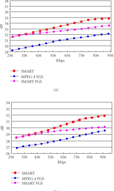
Figure10: The curves of average PSNR versus bit rate at 30 fps with B frame and temporal scalability. (a) Foreman CIFY (30 Hz). (b) Coastguard CIFY(30 Hz).
SMART FGS and SMART use the same coding technique at the base layer. Since only Mode 1 is used in SMART FGS, the enhancement layer coding is essentially the same as that in MPEG-4 FGS. WMV8 provides a very good base layer
compared with MPEG-4; the coding efficiency gain at the
base layer is close to 2.8 dB in Foreman and 1.6 dB in Coast-guard compared with MPEG-4 FGS. But without the
pro-posed enhancement prediction technique, the coding effi
-ciency gain is becoming smaller and smaller with bit rates
increasing. The coding efficiency gain of SMART FGS is only
1.6 dB in Foreman and 0.44 dB in Coastguard at the highest bit rate. However, the SMART curves with the proposed tech-niques present the consistent performance in a wide range of bit rates. The bit rate for the high-quality reference is about 346 kbps in Foreman and 322 kbps in Coastguard. The
coding efficiency gain, when the high-quality reference is
1152 896 640 384 128
kbps
1 577 1153 1729 2305 2881 3457 Frame
Actual Estimate
(a)
1152 896 640 384 128
kbps
1 577 1153 1729 2305 2881 3457 Frame
Actual Estimate
(b)
Figure11: The estimated channel bandwidth in the SMART sys-tem. (a) Estimated bandwidth in bs one sequence. (b) Estimated bandwidth in bs two sequence.
In addition, although the high-quality references are used in the enhancement layer coding, the SMART curves still have the similar performance as the SMART FGS curves at low bit rates. The SMART curve has only about 0.15 dB loss at 150 kbps. This proves that the proposed drifting reduction
technique can effectively control the drifting errors.
In the second set of experiments, the testing sequences are coded at 30 Hz encoding frame rate. Only the first frame is coded as I frame. There are two temporal frames in the scalable coding scheme between a pair of I and P or two P frames. Other experimental conditions are the same as in the first set of experiments. The same experimental results given inFigure 10are observed as in the first set of experiments.
Since neither MPEG-4 FGS nor the SMART codec con-tains one of the switching techniques, for example, S frame, SP frame, or SF frame, the readers who are interested in the comparisons between the scalable video coding and the SP
frame on H.26L TML can read the MPEG proposal in [35].
6.2. Dynamic tests
The dynamic experiments try to test the SMART system un-der the dynamic channel, such as streaming video over the Internet, where the channel bandwidth varies in a wide range of bit rates. The conditions of MPEG-4 FGS verification test
34 33 32 31 30 29 28 27 26 25 24
dB
1 25 49 73 97 121 145
S Dynamic
1024 kbps
(a)
35 33 31 29 27 25
dB
1 25 49 73 97 121 145
S Dynamic
1024 kbps (b)
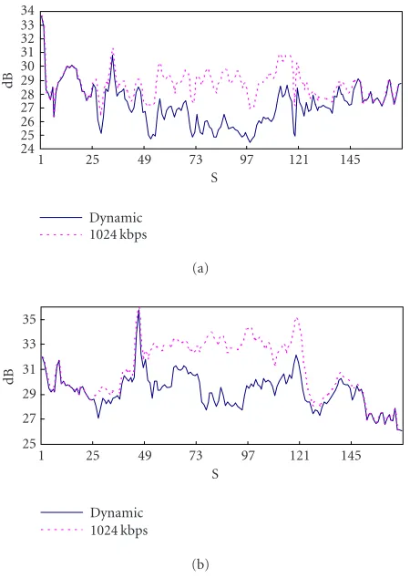
Figure 12: The decoded quality over the dynamic channel: (a) bs oneY. (b) bs twoY.
are used in this experiment [36]. Two CIF sequences, bs one
and bs two, each with 4032 frames (168 seconds at 24 fps) are used. The channel bandwidth varies from 1024 kbps to 256 kbps and then recovers to 1024 kbps again with a step of 256 kbps. Every bit rate lasts 24 seconds. The dynamic chan-nel simulation is done by the commerce simulator, the Cloud
software (http://www.shunra.com).
By using the hybrid model-based and probe-based band-width estimation scheme, when the sequences bs one and bs two are transmitted over the simulated dynamic chan-nel, the estimated bandwidth is recorded and plotted in
The decoded quality of sequences bs one and bs two are
also recorded and plotted inFigure 12. Each sample is the
av-erage PSNR in a second. Two factors, channel bandwidth and
video content, will affect the final decoded quality.
Some-times, even if the channel bandwidth is high, the decoded PSNR may not be high due to active content. In order to eliminate the video content factor in evaluating the perfor-mance of the SMART system on bandwidth adaptation, the
PSNR curves decoded at 1024 kbps are drawn inFigure 12as
reference. The distances between the dynamic curve and the 1024 kbps curve reflect the bandwidth adaptation capability of the SMART system.
As shown inFigure 12, the decoded PSNR is less than that
at 1024 kbps up to 4.4 dB from 73 to 96 seconds because the estimated bandwidth is only 240 kbps around. From 49 to 72 seconds and from 97 to 120 seconds, the estimated channel bandwidth is about 480 kbps. The decoded PSNR is signifi-cantly improved compared with that at 240 kbps. From 25 to 48 seconds and from 121 to 144 seconds, the estimated band-width is about 720 kbps. The decoded PSNR is only slightly less than that at 1024 kbps. The SMART system provides al-most the same quality as that at 1024 kbps from 1 to 24 sec-onds and from 145 to 168 secsec-onds. The estimated bandwidth in these two periods is about 950 kbps. Thus, the SMART sys-tem shows excellent performance on bandwidth adaptation.
Although there are a lot of packet losses while switching the channel bandwidth from high bit rate to low bit rate, with the proposed error resilience technique and unequal error protection, all packet losses at the base layer are recovered in the simulation. No green blocks appeared in the decoded video. For the enhancement bitstreams, there is not any error
protection. The effects of packet losses at the enhancement
layer are gradually recovered by the drifting reduction tech-nique. There are also no obvious visual artifacts and quality degradation in the average PSNR curves.
At last, the SMART video player is given inFigure 13. It
can real-time decode the CIF sequence at 1024 kbps with PIII 800 MHz. The decoded video is presented in the biggest win-dow. The right-upper window shows the curve of the esti-mated channel bandwidth and the right-bottom window is for the program list. The packet loss ratio is drawn in the window between them. A progress bar is used to indicate the
status of the received buffer.
The proposed SMART system is also used to run the re-sults of MPEG-4 FGS verification tests, where the SMART codec is replaced by MPEG-4 FGS codec. The experimental
results have been released in [37].
7. CONCLUSIONS AND FUTURE WORKS
The SMART system presents an efficient, adaptive, and
ro-bust scheme for streaming video over the Internet. Firstly, since the multiple-loop prediction and drifting reduction techniques are applied at the macroblock level, the SMART system can outperform MPEG-4 FGS up to 3.0 dB. Secondly, the SMART system has excellent capability in network band-width and device adaptation due to the embedded
enhance-Figure13: The interface of the SMART video player.
ment bitstreams and the universal scalabilities. Thirdly, with the proposed bandwidth estimation method, the SMART system can rapidly and stably catch bandwidth variations. At last, since a layered bitstream structure with a more impor-tant base layer and less imporimpor-tant enhancement layers is pro-vided in the SMART system, the base layer bitstream is highly protected by the proposed error resilience and unequal error protection techniques with small overhead. The SMART sys-tem can provide users with much smooth playback
experi-ence and much better visual quality in the best-effort
Inter-net.
Although the SMART system shows good performances
on coding efficiency, bandwidth adaptation, channel
estima-tion, and error robustness, there are still several problems needed to be further studied in the future, such as how to
fur-ther improve the coding efficiency to cover an even wider bit
rate range; how to optimally allocate the available bandwidth
to different enhancement layers so that the perception
qual-ity looks better; how to optimally packetize the base layer and the enhancement layer bitstreams so that the packet losses
have less effects; how to optimally decide the parameters in
FEC and ARQ to achieve a better trade-offbetween ARQ
de-lay and FEC overhead; and how to protect those bit planes for reconstruction of the high-quality reference at the en-hancement layers with small overhead. In addition, how to
effectively utilize the features and techniques of the SMART
system in the multicast applications is another topic worthy of further study.
ACKNOWLEDGMENTS
REFERENCES
[1] J. Lu, “Signal processing for Internet video streaming: a re-view,” inProc. SPIE: Image and Video Communications and Processing 2000, vol. 3974, pp. 246–259, San Jose, Calif, USA, January 2000.
[2] A. Luthra, Need for simple streaming video profile, ISO/IEC JTC1/SC29/WG11, M5800, Noordwijkerhout, The Nether-lands, March 2000.
[3] D. Wu, Y. T. Hou, W. Zhu, Y.-Q. Zhang, and J. M. Peha, “Streaming video over the Internet: approaches and direc-tions,” IEEE Trans. Circuits and Systems for Video Technology, vol. 11, no. 3, pp. 282–300, 2001.
[4] RealNetworks facts, 2001, http://www.realnetworks.com/ company.
[5] Windows Media technologies, http://www.microsoft.com/ windows/windowsmedia.
[6] N. Farber and B. Girod, “Robust H.263 compatible video transmission for mobile access to video servers,” inProc. In-ternational Conference on Image Processing, vol. 2, pp. 73–76, Santa Barbara, Calif, USA, October 1997.
[7] M. Jarczewicz and R. Kurceren, A proposal for SP-frames, ITU-T Q.6/SG 16, VCEG-L27, Elysee, Germany, January 2001.
[8] X. Sun, S. Li, F. Wu, G. B. Shen, and W. Gao, “Efficient and flexible drift-free video bitstream switching at predictive frames,” inProc. IEEE International Conference on Multimedia and Expo, vol. 1, pp. 541–544, Lausanne, Switzerland, August 2002.
[9] S. McCanne, V. Jacobson, and M. Vetterli, “Receiver-driven layered multicast,” inProc. Conference on Applications, Tech-nologies, Architectures, and Protocols for Computer Communi-cation (ACM SIGCOMM ’96), pp. 117–130, Stanford, Calif, USA, August 1996.
[10] D.-N. Yang, W. Liao, and Y.-T. Lin, “MQ: an integrated mech-anism for multimedia multicasting,”IEEE Trans. Multimedia, vol. 3, no. 1, pp. 82–97, 2001.
[11] H. Schulzrinne, A. Rao, and R. Lanphier, Real time streaming protocol (RTSP), Internet Engineering Task Force, Internet draft, RFC 2326, April 1998.
[12] H. Schulzrinne, S. Casner, R. Frederick, and V. Jacobson,RTP: A transport protocol for real-time applications, Internet Engi-neering Task Force, Internet draft, RFC 1889, January 1996. [13] MPEG video group, Information technology—Generic coding
of moving pictures and associated audio, ISO/IEC 13818-2, In-ternational standard, 1995.
[14] MPEG video group, Generic coding of audio-visual objects: part 2, ISO/IEC 14496-2, International standard, 1998. [15] ITU-T Recommendation H.263, Video coding for low bit rate
communication, Version 2, 1998.
[16] W. Li, “Overview of fine granularity scalability in MPEG-4 video standard,” IEEE Trans. Circuits and Systems for Video Technology, vol. 11, no. 3, pp. 301–317, 2001.
[17] M. van der Schaar and H. Radha, “A hybrid temporal-SNR fine-granular scalability for Internet video,” IEEE Trans. Cir-cuits and Systems for Video Technology, vol. 11, no. 3, pp. 318– 331, 2001.
[18] F. Wu, S. Li, and Y.-Q. Zhang, “DCT-prediction based pro-gressive fine granularity Scalability coding,” inProc. Interna-tional Conference on Image Processing (ICIP ’00), vol. 3, pp. 566–569, Vancouver, British Columbia, Canada, September 2000.
[19] F. Wu, S. Li, and Y.-Q. Zhang, “A framework for efficient progressive fine granularity scalable video coding,” IEEE Trans. Circuits and Systems for Video Technology, vol. 11, no. 3, pp. 332–344, 2001.
[20] X. Sun, F. Wu, S. Li, W. Gao, and Y.-Q. Zhang, “Macroblock-based progressive fine granularity scalable video coding,” in Proc. IEEE International Conference on Multimedia and Expo (ICME ’01), pp. 461–464, Tokyo, Japan, August 2001. [21] F. Wu, S. Li, B. Zeng, and Y.-Q. Zhang, “Drifting reduction
in progressive fine granular scalable video coding,” inProc. Picture Coding Symposium, Seoul, Korea, April 2001. [22] X. Sun, F. Wu, S. Li, W. Gao, and Y.-Q. Zhang,
“Macroblock-based progressive fine granularity scalable (PFGS) video cod-ing with flexible temporal-SNR scalablilities,” inProc. Inter-national Conference on Image Processing, pp. 1025–1028, Thes-saloniki, Greece, October 2001.
[23] Q. Wang, F. Wu, S. Li, Y. Zhong, and Y.-Q. Zhang, “Fine-granularity spatially scalable video coding,” in Proc. IEEE Int. Conf. Acoustics, Speech, Signal Processing, pp. 1801–1804, Salt Lake City, Utah, USA, May 2001.
[24] R. Yan, F. Wu, S. Li, R. Tao, and Y. Wang, “Efficient video coding with hybrid spatial and fine-grain SNR scalabilities,” in Proc. SPIE: Visual Communications and Image Processing 2002, vol. 4671, pp. 850–859, San Jose, Calif, USA, January 2002. [25] R. Kalluri and M. van der Schaar, Single-loop
motion-compensated based fine-granular scalability (MC-FGS) with cross-checked results, ISO/IEC JTC1/SC29/WG11, M6831, Pisa, Italy, 2001.
[26] A. Reibman, L. Bottou, and A. Basso, “DCT-based scalable video coding with drift,” inProc. International Conference on Image Processing, pp. 989–992, Thessaloniki, Greece, October 2001.
[27] A. Reibman and L. Bottou, “Managing drift in DCT-based scalable video coding,” inProc. IEEE Data Compression Con-ference, pp. 351–360, Salt Lake City, Utah, USA, April 2001. [28] W.-H. Peng and Y. K. Chen, “Mode-adaptive fine granularity
scalability,” inProc. International Conference on Image Process-ing, pp. 993–996, Thessaloniki, Greece, October 2001. [29] D. Wu, Y. T. Hou, W. Zhu, et al., “On end-to-end
architec-ture for transporting MPEG-4 video over the Internet,”IEEE Trans. Circuits and Systems for Video Technology, vol. 10, no. 6, pp. 923–941, 2000.
[30] S. Floyd and K. Fall, “Promoting the use of end-to-end con-gestion control in the Internet,” IEEE/ACM Transactions on Networking, vol. 7, no. 4, pp. 458–472, 1999.
[31] M. Handley, S. Floyd, J. Padhye, and J. Widmer,TCP friendly rate control (TFRC): Protocol specification, Internet Engineer-ing Task Force, Internet draft, RFC 3448, January 2003. [32] A. E. Mohr, E. A. Riskin, and R. E. Ladner, “Unequal loss
pro-tection: graceful degradation of image quality over packet era-sure channels through forward error correction,” IEEE Jour-nal on Selected Areas in Communications, vol. 18, no. 6, pp. 819–828, 2000.
[33] P. A. Chou and Z. Miao, “Rate-distortion optimized sender-driven streaming over best-effort networks,” inProc. IEEE 4th Workshop on Multimedia Signal Processing, pp. 587–592, Cannes, France, October 2001.
[34] Video group,Information technology—Coding of audio-visual objects part 5, Amendment 1: Reference software for MPEG-4, ISO/IEC JTC1/SC29/WG11, MPEG M4711, Jeju, March 2002. [35] F. Wu, X. Sun, and S. Li,Comparisons between PFGS and JVT SP, ISO/IEC JTC1/SC29/WG11, MPEG m8426, Fairfax, 2002. [36] Test group,MPEG-4 visual fine granularity scalability tools ver-ification test plan, ISO/IEC JTC1/SC29/WG11, MPEG N4456, Pattaya, Thailand, 2001.
Feng Wureceived his B.S. degree in electri-cal engineering from the University of Xi’an Electrical Science and Technology, Xi’an, China, in 1992, and his M.S. and Ph.D. degrees in computer science from Harbin Institute of Technology, Harbin, China, in 1996 and 1999, respectively. He joined Mi-crosoft Research Asia, Beijing, China, as an Associate Researcher in 1999 and was promoted to a Researcher in 2001. He has
played a major role in Internet Media Group in developing scal-able video coding and streaming technologies. He has authored and coauthored over 60 papers in video compression and contributed some technologies to MPEG-4 and H.264. His research interests in-clude video and audio compression, multimedia transmission, and video segmentation.
Honghui Sunreceived his B.S. degree from Zhejiang University, Hang Zhou, China, in 1992, and his M.S. degree in computer graphics from Beijing University, Beijing, China, in 1995, all in computer science. He was a Lecturer in Computer Science Depart-ment, Beijing University, Beijing, China, from 1995 to 1999. He joined Microsoft Re-search Asia, Beijing, China as a ReRe-search Software Design Engineer in 1999 and was
promoted to Senior Research Software Design Engineer in 2001. His work mainly focuses on video compression, multimedia trans-mission, and network technology.
Guobin Shenreceived his B.S. degree from Harbin University of Engineering, Harbin, China, in 1994, his M.S. degree from Southeast University, Nanjing, China, in 1997, and his Ph.D. degree from the Hong Kong University of Science and Technol-ogy (HKUST) in 2001, all in electrical en-gineering. He was a Research Assistant at HKUST from 1997 to 2001. Since then, he has been with Microsoft Research Asia. His
research interests include digital image and video signal processing, video coding and streaming, peer-to-peer networking, and parallel computing.
Shipeng Lireceived his B.S. and M.S. de-grees from the University of Science and Technology of China (USTC) in 1988 and 1991, respectively, and the Ph.D. degree from Lehigh University, Bethlehem, PA, in 1996, all in electrical engineering. He was with the Electrical Engineering Depart-ment, University of Science and Technol-ogy of China, Hefei, China, from 1991 to 1992. He was a member of the technical
staffat SarnoffCorporation, Princeton, NJ, from 1996 to 1999. He has been a Researcher with Microsoft Research China, Beijing, since May 1999. His research interests include image/video com-pression and communications, digital television, multimedia, and wireless communication. He has contributed some technologies to MPEG-4 and H.264.
Ya-Qin Zhangreceived the B.S. and M.S. degrees in electrical engineering from the University of Science and Technology of China (USTC), Hefei, Anhui, China, in 1983 and 1985, and the Ph.D. degree in elec-trical engineering from George Washing-ton University, WashingWashing-ton, DC, in 1989. He is currently the Managing Director of Microsoft Research Asia, Beijing, China, in 1999. He has authored and coauthored over
200 refereed papers in leading international conferences and jour-nals, and has been granted over 40 US patents in digital video, Internet, multimedia, wireless, and satellite communications. Dr. Zhang served as Editor-in-Chief for the IEEE Trans. on Circuits and Systems for Video Technology from July 1997 to July 1999. He was the Chairman of the Visual Signal Processing and Communications Technical Committee of the IEEE Circuits and Systems (CAS) So-ciety. He has received numerous awards, including several industry technical achievement awards and IEEE awards, such as the CAS Jubilee Golden Medal. He recently received the Outstanding Young Electrical Engineer of 1998 Award.
Bruce Linreceived his B.S. degree from Na-tional Taiwan University in 1988 and his M.S. and Ph.D. degrees from the Univer-sity of Maryland, College Park, in 1994 and 1996, respectively, all in computer science. He was a Research Assistant at the center for automatic research at the University of Maryland from 1992 to 1995. Since 1995, he has been working with Microsoft on video compression. Currently, he is a
Develop-ment Manager of Media Processing Technology group in Microsoft Digital Media Division. His focus is on Windows media video and various image/video processing components for Windows.
Ming-Chieh Leewas born in Taiwan. He received his B.S. degree in electrical engi-neering from the National Taiwan Univer-sity, Taiwan, in 1988, and his M.S. and Ph.D. degrees in electrical engineering from Cali-fornia Institute of Technology, Pasadena, in 1991 and 1993, respectively. His Ph.D. re-search topic was on still and moving image compression using multiscale techniques. From January 1993 to December 1993, he