A Magic-T Integrated 5.8-GHz Repeater Array Antenna Using
Dual-Feed Network
Thet Paing Phyoe*, Eisuke Nishiyama, and Ichihiko Toyoda
Abstract—In this paper, a novel high-gain repeater antenna integrating a dual-feed network is proposed to receive and transmit RF signals separately by two ports. The proposed array antenna has four linearly polarized microstrip antenna elements, two feed networks, and one planar magic-T. The distance between the elements of the array antenna is matched to obtain the minimum sidelobe level and maximum half-power beamwidth for transmitting and receiving purpose. The planar magic-T is effectively used to meet two different bi-directional radiation patterns with a simple structure. Performances of the array antenna are experimentally confirmed, and the gain of the antenna for each port is better than 10.3 dBi. The measured 10-dB impedance bandwidth of the antenna is wider than 580 MHz (10%).
1. INTRODUCTION
In wireless communication systems, repeaters are widely used to reduce the path loss between the transmitters and receivers within the limited communication range. High-power transmitters are required to control the path loss especially in high-frequency environments and extend the signal coverage. The repeater is one of the cost-effective solutions for the extension of the coverage area with the low signal levels. In repeater systems, frequency division duplex (FDD) method which separates the frequencies of the uplink and downlink signals and time division duplex (TDD) method which transmits or receives the signals by the allocation of different time slots in the same frequency band were used. Therefore, TDD requires only one interference-free channel, and it allows interference mitigation with the proper frequency planning. Moreover, the TDD system eliminates the complexity and costs associated with isolating the transmitting and receiving antennas because it reuses the filters, mixers, frequency sources, etc. Currently, the TDD based array antennas are very popular in the Internet of Things (IoT) and cloud-based applications [1, 2].
Different types of antennas for repeater applications were proposed [3–5]. A wide-band indoor repeater antenna [6] and miniaturized antennas [7, 8] were introduced. However, these antennas [3–8] have a low gain, and high-gain antennas are required to increase the overall repeater gain. Therefore, an indoor repeater antenna using metamaterials [9] and a dual-fed ICS repeater antenna using parasitic patches [10] have been reported to increase the gain and isolation. Nevertheless, its gain is still low because the transmitting and receiving antennas are separately used.
Nowadays, array antennas are used to increase the gain of the antenna. However, the array antennas have narrow beamwidth and unwanted sidelobes. The first sidelobe of the radiation patterns is the main source of electromagnetic interference (EMI), and the sidelobe level suppression is one of the most basic and critical issues in the applications of the array antenna. Therefore, various techniques have been used to reduce the sidelobe level without disturbing the beamwidth of the main beam. Numerical analysis on element spacing was introduced to optimize the sidelobe characteristics of the array antennas [11].
Received 12 January 2019, Accepted 7 March 2019, Scheduled 21 March 2019
* Corresponding author: Thet Paing Phyoe ([email protected]).
Genetic algorithm [12] and coefficient array [13] techniques have been discussed to reduce the sidelobe level for the array antennas.
In this paper, a new 5.8-GHz dual-feed repeater array antenna is proposed, and the performance of the antenna is experimentally examined with a prototype. Two different bi-directional radiation patterns are separately obtained for Port 1 and Port 2 by effectively using the planar magic-T and an additional 90◦ phase shift of the signals. The proposed antenna provides higher antenna gain because all antenna elements of the array antenna are used to receive the RF wave and retransmit the amplified signal. The effects of element spacing of the array antenna are numerically investigated to get the better antenna performance on the radiation patterns in terms of gain, half-power beamwidth, and sidelobe level. The proposed antenna is suitable for the TDD repeater systems because only one of the two ports will be used at the same time.
2. DESIGN OF A DUAL-FEED REPEATER ARRAY ANTENNA
In a repeater system, the repeater amplifies the received signals from the base station and retransmits the signals to the end users via its transmitting antennas. In this paper, only antenna part is designed to obtain high gain, and amplifier is not considered. The overall gain of the repeater system can be defined as the following equation:
GαGrGampGt (1)
where G, Gr, Gamp, and Gt are the overall repeater gain, receiving antenna gain, amplifier gain, and transmitting antenna gain, respectively. According to the equation, the overall repeater gain is proportional to the product of the transmitting and receiving antennas’ gains of the repeater system. Therefore, high-gain antennas are required to enhance the repeater gain.
2.1. Antenna Structure
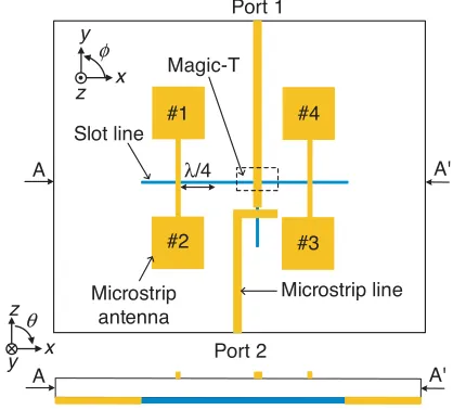
Figure 1 shows the structure of the proposed 5.8-GHz dual-feed repeater array antenna. The antenna consists of four linearly polarized microstrip antenna elements, a dual-feed network using a slot-T type planar magic-T. The four antenna elements are equally spaced to avoid the gain drop due to far-field cancellation and reduce the sidelobe level of the radiation patterns. The microstrip lines of antenna elements #1 and #2 are combined and connected to the magic-T via a slot line. In the same way, antenna elements #3 and #4 are combined and connected to the magic-T. In this structure, antenna elements #3 and #4 are 90◦ ahead of the other antenna elements #1 and #2 to generate the bi-directional radiation patterns in the φ = 0◦ plane. An additional quarter-wavelength slot line is used
#1 #4
#3 #2
Port 2 Magic-T
λ/4
Port 1
Slot line
Microstrip line Microstrip
antenna
z y
x
y z
x
A A'
A A'
θ
φ
for 90◦ phase shift of the signal. The microstrip line of the magic-T is connected to Port 1, and the slot line is converted to a microstrip line and connected to Port 2. All microstrip antenna elements and microstrip lines are designed on the top side of the substrate, whereas the slot lines are located at the bottom side of the substrate. In this structure, Port 1 will be used to retransmit the amplified signals if Port 2 is used to receive the signals for a radio repeater. In the real applications of the repeater system, one port of the antenna connects to the input of the repeater circuit, and the other port is connected to the output of the circuit.
2.2. Magic-T
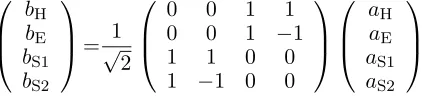
Figure 2 shows the structure and an equivalent circuit of a slot-T type planar magic-T. The magic-T is an RF signal combiner/divider with 0◦ and 180◦ phase difference, and the magic-T is designed using a slot line T branch and a microstrip-slot line T branch. TheS-matrix of the magic-T can be expressed as the following equation.
⎛ ⎜ ⎝ bH bE bS1 bS2 ⎞ ⎟ ⎠=√1
2 ⎛ ⎜ ⎝
0 0 1 1
0 0 1 −1
1 1 0 0
1 −1 0 0
⎞ ⎟ ⎠ ⎛ ⎜ ⎝ aH aE aS1 aS2 ⎞ ⎟ ⎠ (2)
As shown in Equation (2) and Figure 2, the input signal from Port H is distributed into two in-phase signals and emerges to Ports S1 and S2 as shown by the red arrows. On the other hand, the input signal from Port E outputs to the Ports S1 and S2 in anti-phase as shown by the blue arrows. In this proposed structure, a microstrip line is extended by a quarter wavelength over the slot line to separate the RF signal properly. Here, Ports H and E are isolated from each other due to the difference of the propagation modes.
(b) (a) Microstrip line Slot line 2Z0 Z0 Z0
Z0/2
Z0
H
E
M2
Figure 2. Slot-T type planar magic-T. (a) Structure. (b) Equivalent circuit.
When the signal is fed from Port H, microstrip-slot line T branch is a parallel branch, and the impedance of Port H is half of the impedance of Ports S1 and S2 [14, 15]. On the other hand, the impedance of Port E is the double of the impedance of Ports S1 and S2 because slot line T branch is a series branch. However, a quarter-wavelength impedance transformer is used in the actual design to reduce the slot line radiation effects, and the impedance of Port E is designed to be equal to the impedance of PortsS1 and S2.
2.3. Operating Principle
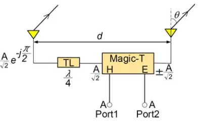
Figure 3. Basic concept of the proposed antenna.
of an input signal for Ports 1 and 2. The array factor is given as the following equation.
f(θ) =
2
n=1
Ine[j(n−1)(kdsinθ)] (3)
where In, k, and d are the complex amplitude of the excitation of the nth element, free space wave number, and the separation between two antenna elements, respectively.
When the signal is fed from Port 1, the array factor is expressed as follows:
f(θ) = √A 2e
−jπ2 +√A 2e
j(kdsinθ)= √A
2e
−jπ2[1 +ej(kdsinθ+π2)] (4)
The array factorf(θ) of the antenna elements has a maximum if ej(kdsinθ+π2)= 1. Therefore,
kdsinθ+π 2 = 0 sinθ=−
π
2
kd, k= 2π
λ whereλis the wavelength of the antenna and then
θ= sin−1 −λ 4d
. (5)
According to Equation (5), the peak can be found at the angle of −16◦ for the designed frequency of 5.8 GHz and 46 mm antenna separation.
On the other hand, the array factor for Port 2 is expressed by:
f(θ) = √A 2e
−jπ2 −√A 2e
j(kdsinθ)
. (6)
In this case,ej(kdsinθ+π2)=−1 whenf(θ) is maximum. Therefore,
kdsinθ+π
2 =π, θ= sin
−1 λ
4d
. (7)
When the signal is fed from Port 2, the peak is obtained at the angle of +16◦. Therefore, Port 1 and Port 2 generate bidirectional radiation patterns, and the direction of peak radiation can be controlled by changing the ports.
(b) (a)
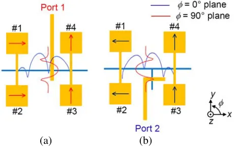
Figure 4. Phase relations of the antenna elements. (a) Port 1 feed. (b) Port 2 feed.
(b)
(a) (c) (d)
Figure 5. Simulated 3D radiation patterns of the proposed array antenna at 5.8 GHz. (a) Port 1 (φ= 0◦). (b) Port 1 (φ= 90◦). (c) Port 2 (φ= 0◦). (d) Port 2 (φ= 90◦).
the signal is fed from Port 2. However, the resultant phases of the antenna elements #1 and #2 (#3, and #4) are the same. Therefore, the radiation patterns of the array antenna shown by the red curves have the maximum at the center in theφ= 90◦ plane.
Figure 5 shows the 3D radiation patterns of the 5.8-GHz array antenna simulated by using Keysight Technologies’ Advanced Design System (ADS) Momentum. The green lines in the middle of the 3D patterns show cutting planes of the antenna. In the φ= 90◦ plane, radiation patterns of the antenna are almost the same for both ports, and the peak of the radiation pattern can be found at θ = 0◦. However, radiation patterns of the array antenna in the φ = 0◦ plane are opposite. The peak of the radiation patterns in theφ= 0◦ plane can be seen at θ=−14◦ for Port 1 and θ= +14◦ for Port 2.
2.4. Parametric Studies and Optimization
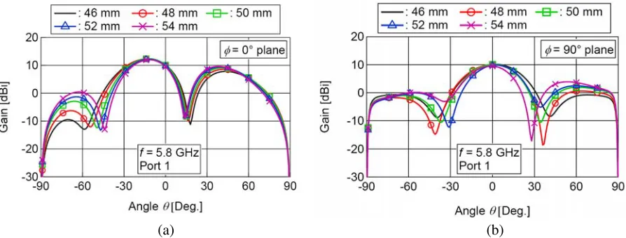
Figure 6 depicts simulated radiation patterns of the proposed antenna for Port 1. The two graphs illustrate the effects of the element spacing of the array antenna on the gain, sidelobe level (SLL), and half-power beamwidth (HP-BW) of the antenna. The element spacing of the antenna in this simulation means the changing distance between the center-to-center elements (patches #1, #2 and #3, #4) and (patches #1, #4 and #2, #3). However, the spacings between patches #1, #2 and #1, #4 are equal, and the simulated frequency is 5.8 GHz. According to the results, the element spacing has an effect on radiation patterns of the antenna. The gains of the antenna have a maximum at θ=−14◦ forφ= 0◦ plane andθ= 0◦ forφ= 90◦ plane.
(b) (a)
Figure 6. Simulated radiation patterns of the antenna with respect to the element spacing for Port 1. (a)φ= 0◦ plane. (b)φ= 90◦ plane.
Table 1. Performance comparison with respect to the element spacing for Port 1 (f = 5.8 GHz).
Element spacing (mm)
φ= 0◦ plane φ= 90◦ plane
Gain (dBi) HP-BW
(deg.) SLL (dB) Gain (dBi)
HP-BW
(deg.) SLL (dB)
46 12.3 32 −4.6 10.3 35 −10.3
48 12.4 30 −4.0 10.3 33 −9.4
50 12.4 29 −3.4 10.4 31 −8.2
52 12.2 28 −2.9 10.1 29 −7.4
54 12.0 27 −2.4 9.8 28 −5.7
(b) (a)
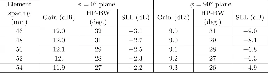
Figure 7. Simulated radiation patterns of the antenna with respect to the element spacing for Port 2. (a)φ= 0◦ plane. (b)φ= 90◦ plane.
Table 2. Performance comparison with respect to the element spacing for Port 2 (f = 5.8 GHz).
Element spacing
(mm)
φ= 0◦ plane φ= 90◦ plane
Gain (dBi) HP-BW
(deg.) SLL (dB) Gain (dBi)
HP-BW
(deg.) SLL (dB)
46 12.0 32 −3.1 9.0 31 −9.0
48 12.0 31 −2.7 9.0 29 −8.1
50 12.1 29 −2.5 9.1 28 −6.8
52 12. 28 −2.3 9.2 27 −6.3
54 11.9 27 −2.2 9.3 26 −4.9
Port 1 and Port 2, respectively.
Based on Figure 7, the performance comparison of the antenna can be seen in Table 2. The simulated gains of the proposed array antenna are 12 dBi for theφ= 0◦ plane and 9 dBi for theφ= 90◦ planes. Tables 1 and 2 show that the antenna has the same performance for Port 1 and Port 2. Therefore, the proposed dual-feed array antenna can be used for a single frequency repeater.
Figure 8 shows the simulated gain of the proposed antenna with respect to the frequency. The element spacing used in these graphs is 46 mm because it provides minimum sidelobe level and maximum half-power beamwidth. The simulated gains of the antenna are calculated at θ = ±14◦ and θ = 0◦, where peak gains are observed for Port 1 and Port 2, respectively. According to the results, more than 10 dBi gain is achieved for Port 1 and Port 2.
(b) (a)
Figure 8. Simulated antenna gain with respect to the frequency for the optimum element spacing of 46 mm. (a) Port 1. (b) Port 2.
3. ANTENNA PERFORMANCES
Figure 9 shows a prototype of the proposed 5.8-GHz repeater array antenna, and the size of the antenna is 120 mm×115 mm. The prototype of the proposed antenna is developed on a Teflon fiber substrate of 0.8-mm thickness and permittivity of 2.15. The antenna element spacing is 0.9λ0 (46 mm), and all
port impedances are designed to be 50 Ω.
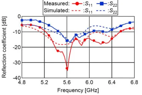
Figure 10 shows the measured and simulated reflection coefficients of the antenna. Better than
(b) (a)
Figure 9. Prototype of the proposed 5.8-GHz dual-feed repeater array antenna (120 mm×115 mm). (a) Top view. (b) Bottom view.
Figure 10. Reflection coefficient. Figure 11. Isolation.
(b) (a)
Figure 12. Radiation patterns of the array antenna for Port 1. (a) φ= 0◦ plane. (b)φ= 90◦ plane.
Figure 11 shows the measured and simulated isolations of the antenna. The proposed antenna has 17-dB isolation between two ports, and it is suitable for the TDD repeater system.
good performance of the antenna. As shown in Figure 12, the measured and simulated peak gains of the antenna are obtained around θ = −14◦ for φ = 0◦ plane and θ = 0◦ for φ = 90◦ plane, and the radiation patterns are well matched. The measured gains of the antenna are 10.7 dBi and 8.4 dBi for theφ= 0◦ and φ= 90◦ planes, respectively.
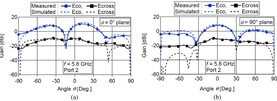
Figure 13 shows the measured and simulated radiation patterns of the proposed antenna for Port 2. The performances of the antenna are investigated at 5.8 GHz in both planes. The peak gains of the antenna can be found at θ= +14◦ forφ= 0◦ plane and θ= 0◦ forφ= 90◦ plane. The simulated and measured cross-polarization suppressions are around 25 dB in both planes. The measured gains of the array antenna are 10.4 dBi and 7.9 dBi for the φ = 0◦ and φ= 90◦ planes, respectively. According to Figures 12 and 13, the proposed antenna has two different bi-directional radiation patterns for Port 1 and Port 2.
Finally, the proposed antenna is compared with the previously reported antennas, and the performance comparison of the antennas is presented in Table 3. As shown in this table, the advantages of the proposed antenna are clear to see, and it has a higher antenna gain for the transmitting and receiving purpose. Moreover, the proposed antenna provides good impedance bandwidth with a simple structure.
(b) (a)
Figure 13. Radiation patterns of the array antenna for Port 2. (a) φ= 0◦ plane. (b)φ= 90◦ plane.
Table 3. Comparison of the proposed antenna with previous antenna.
Ant. Imp. BW. No. of ant.
elements
Isolation (dB)
Tran. ant. gain (dBi)
Rec. ant. gain (dBi)
φ= 0◦ φ= 90◦ φ= 0◦ φ= 90◦
[5] 3.9 GHz
3.4–7.3 GHz 1 17.2 <4.4 <4.4
[6] 580 MHz
1.92–2.5 GHz 4 80 >3.9 >3.9 >3.9 >3.9
[8] ∼15 MHz 4 54 −1 −1.3
[9] 0.2 GHz
2.3–2.5 GHz
4 main & 4
parasitic patches 80 9.6 9.6 9.6 9.6
[10] 136 MHz
804–940 MHz
2 main & 2
parasitic patches 56 >4 >4 >4 >4 Proposed
ant.
1.32 GHz
4. CONCLUSION
In this paper, a new 5.8-GHz dual-feed array antenna employing a planar magic-T and additional quarter-wavelength slot line is examined in detail using a prototype antenna. The proposed array antenna separately generates two different bi-directional radiation patterns by Port 1 and Port 2. The sidelobe level, gain, and half-power beamwidth of the antenna are optimized to obtain a better antenna performance. Measured results show that the proposed array antenna achieves higher antenna gain with a simple structure, and it will improve the overall system gain of the repeater. Therefore, the proposed antenna is useful in repeater applications for various wireless communication systems.
ACKNOWLEDGMENT
The authors would like to thank Dr. Takayuki Tanaka, Saga University for his fruitful discussions.
REFERENCES
1. Choi, J.-Y., M.-S. Hur, Y.-W. Suh, J.-S. Baek, Y.-T. Lee, and J.-S. Seo, “Interference cancellation techniques for digital on-channel repeaters in T-DMB system,” IEEE Trans. Broadcast., Vol. 57, No. 1, 46–56, 2011.
2. Yang, X., W. Lu, N. Wang, K. Nieman, C.-K. Wen, C. Zhang, S. Jin, X. Mu, I. Wong, Y. Huang, and X. You, “Design and implementation of a TDD-based 128-antenna massive MIMO prototype system,” China Communications, Vol. 14, No. 12, 162–187, 2017.
3. Yang, Z., X. Zhang, X. Teng, Z. Zhang, S. Li, and Y. Wang, “A novel low profile box-shaped antenna for a repeater system,”Proc. 2012 the 10th Int’l Symp. Antennas Propag. and EM Theory (ISAPE), 93–96, Xi’an, China, 2012.
4. Komaki, K., and H. Iwasaki, “Back to back patch antenna operated orthogonal polarization for repeater use,”Proc. 2015 Int’l Symp. Antennas Propag. (ISAP), 1–2, Tasmania, Australia, 2015. 5. Duan, Z., L.-J. Xu, and W. Geyi, “Metal frame repeater antenna with partial slotted ground for
bandwidth enhancement of wristband devices,” IET Microw. Antennas Propag., Vol. 11, No. 10, 1438–1444, 2017.
6. Lee, Y., J. Ha, and J. Choi, “Design of a wideband indoor repeater antenna with high isolation for 3G systems,” IEEE Antennas Wireless Propag. Lett., Vol. 9, 697–700, 2010.
7. Sarabandi, K., and Y. J. Song, “Subwavelength radio repeater system utilizing miniaturized antennas and metamaterial channel isolator,” IEEE Trans. Antennas Propag., Vol. 59, No. 7, 2683–2690, 2011.
8. Song, Y. J. and K. Sarabandi, “Miniaturized radio repeater for enhanced wireless connectivity of Ad-Hoc networks,” IEEE Trans. Antennas Propag., Vol. 60, No. 8, 3913–3920, 2012.
9. Lee, Y., J. Ha, and J. Choi, “Design of an indoor repeater antenna with high isolation using metamaterials,” Microwave and Optical Tech. Lett., Vol. 54, No. 3, 755–761, 2012.
10. Ko, J.-H., G.-K. Kim, S.-Y. Rhee, and J.-I. Lee, “800 MHz band dual-fed ICS repeater antenna with high isolation,” Journal Korea Inst. Inf. Commun. Eng. (Korean Edition), Vol. 20, No. 5, 867–873, 2016.
11. Safaai-jazi, A. and W. L. Stutzman, “A new low sidelobe pattern synthesis technique for equally spaced linear arrays,”IEEE Trans. Antennas and Propag., Vol. 64, No. 4, 1317–1324, 2016. 12. Cesar, C. G., I. Santamaria, J. Via, E. M. Gomez, and T. S. Paules, “Robust array beamforming
with sidelobe control using support vector machines,”IEEE Trans. Signal Process., Vol. 55, No. 2, 574–584, 2007.
13. Mikunide, A. and M. Fujimoto, “Specific area communication system using binomial coefficient array,”Proc. 2017 Int’l Symp. Antennas Propag. (ISAP), 1–2, Phuket, Thailand, 2017.