CSEIT1723354 | Received : 26 June 2017 | Accepted : 03 July 2017 | July-August-2017 [(2)4: 07-17]
International Journal of Scientific Research in Computer Science, Engineering and Information Technology © 2017 IJSRCSEIT | Volume 2 | Issue 4 | ISSN : 2456-3307
7
Lane Recognition Technique Using Hough Transform
Pallavi V. Ingale, Prof. K. S. Bhagat, Dr. D K. Kirange
Electronic and Telecommunication Engineering Department, J.T.Mahajan College of Engineering, North Maharashtra University, Faizpur, Maharashtra, India
ABSTRACT
In India, the rate of fatality due to accidents cases increases year by year. This problem becomes more serious and need all concerns to immediately take the following urgent actions in order to save precious human life. Therefore, this paper attempts to present a technique based on video and image processing for lane guidance warning system as an alternative way to reduce the accident rate due to lane departure. This system is capable to identify two lane markings from the video captured through a webcam. Warning system will automatically „switch on‟ once lane departure occurs either to the right or to the left side of the road. The input video will first undergo threshold process and binary conversion. Then, lane marking detection is done using Hough transform, Hough line detection and local maxima finder. Finally, a decision-making algorithm is applied in the system to detect lane departure. It is found that, this system is able to identify straight lane markers, highlighting both markers with colour lines and able to give appropriate warning when lane crossing happen. For future enhancement, distance measuring function should be applied in the system so that the distance from one vehicle in front with another one at the back can be measured automatically.
Keywords : Car Lane Recognition System, Threshold, Image And Video Processing, Hough Transform, CHEVP Algorithm
I.
INTRODUCTION
With the rapid raise of urban traffic, the traffic safety becomes more and more significant. Leaving the lane causes about 30% of all accidents in the highway, and most of these are resulted from the distraction and fatigue of the driver. Therefore, a system that could provide a warning to drivers of a danger has a great potential to save a large number of lives. Most of these accident casualties are the results of the abnormal lane switching by drivers on the highway which may be caused by drivers‟ tiredness, illness and loss of concentration. Thus, developing a method to keep the vehicles always on their lane is necessary in order to reduce the percentage of unexpected lane departure of vehicles on the highway. Therefore, it‟s necessary to investigate a driver assistant system which can remind the driver when needed.
Figure 1. Block diagram of a Lane Departure Warning (LDW) System
This system could help driver to drive within the lane and able to warn him if the vehicle is departing from the current lane. In this project, MATLAB software is used for complex image refining and complex calculation of image processing algorithm. Video and image processing toolbox is implemented to perform lane detection. The main objective of this system is to assist driver to continuous monitoring the lane marking on both sides of the road. Moreover, it can reflect to marking on both sides of the road.
II.
LITERATURE SURVEY
Safe driving is the main motivation behind the driver assist systems. Bing-Fei Wu et al. explained that the DSP image processor on ALDWS works with operating frequency of 600MHz and the lane marking detection speed can be more than 35 frames per second with Quarter Video Graphics Array (QVGA) size [5]. O. Khalifa et al. described the algorithm which uses a combination of scan boundary lines and Hough transform to fit a hyperbola pair model [2]. Joshua M. Clanton et al. explain a method fusing GPS/inertial navigation sensor/vision and a high-accuracy map for highway lane tracking. This method provides a backup lateral offset measurement that can be used for LDW when the LDW vision system loses track of the lane markings [7]. In Yong Zhou et al. [8], it is proposed Virtual boundary based Lane departure Warning Method (VLWM) which allows the driver to drift beyond the physical lane boundary by adding a virtual lane boundary. Accounting for the driving habit of the driver, lane geometry, and the local driver behavior changes, the virtual lane width is determined using a fuzzy-logic inference method.
Juan M. Collado has shown that a parabolic lane model is fitted to road markings and tracked through a particle filter. The right and left lane boundaries are classified in three types (solid, broken or merge lane boundaries), through a Fourier analysis, and adjacent lanes are searched when broken or merge lines are detected. Pei-Yung Hsiao et al. in 2006 made a design of the embedded lane departure warning system on a custom board to gain enough capability to carry out the huge calculations for lane departure warning algorithms [9]. Joel C. McCall et al. performed a work on Video-Based Lane Estimation and Tracking (VioLET) system which is designed using steerable filters for robust and accurate lane-marking detection with the help of an
up-to-date and comprehensive analysis of the current state of the art in lane-detection research [11]. Yue Wang et al. in 2003 described the B-Snake based lane model which is able to explain a wider range of lane structures since B-Spline can form any arbitrary shape by a set of control points which can be determined by a minimum error method called Minimum Mean Square Error (MMSE) and a robust algorithm, called CHEVP (Canny/Hough Estimation Of Vanishing Point) [8]. As in proposed in Yue Wang et al. in 1998, Catmull-Rom spline can form arbitrary shapes by control points as it can describe a wider range of lane structures than other lane models such as straight and parabolic model, and also, formulates the lane detection problem in the form of determining the set of lane model control points.
III.
SYSTEM DEVELOPMENT
Car lane guidance system consists of two different major components. The first is lane detection unit and the second is decision-making warning unit. The most important part in this system is to identify lane markers on the road. In this project, webcam is connected on the front board of a vehicle and in fact, it can be installed anywhere behind the windshield as well which might be able to capture more clear image of the entire lane. This webcam will continuously capture video and later sends the data to the computer for further process. The steps of the system operation are briefly explained as follows:
1) Place a webcam at the appropriate position behind the windshield. Adjust the camera and program setting for best view angle and region of interest. 2) Convert the video captured into frames of images.
Then, digitalized the images for threshold process. 3) Apply the lane identification algorithm to detect the
lane marking
4) Determine the position of the vehicle, whether the vehicle is departing from its current lane
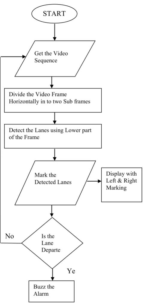
Figure 2 : Flowchart of the proposed LDW system
A. Input Video Selection
Input video from the Camera mounted on the rear view mirror of the car is taken with different road sections under different lighting conditions. Fig. 2 shows the flowchart of the proposed LDW system
B. CHEVP Algorithm
(Canny/Hough Estimation of Vanishing Points)
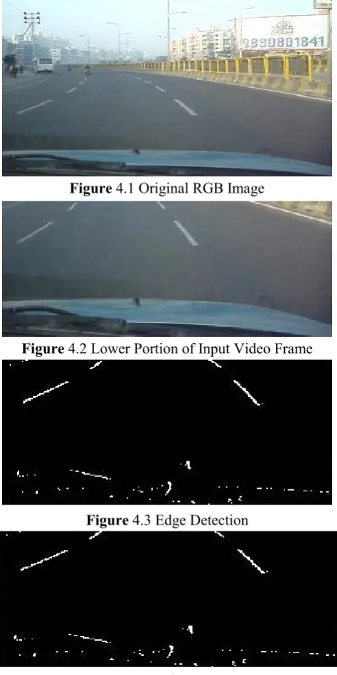
This algorithm is used for the edge detection and the lane marking system. Automatic initialization technique, able to extract the location of any type of the lane shapes, is important and necessary. The CHEVP (Canny/Hough Estimation of Vanishing Points) algorithm has been developed to meet these requirements. The road is assumed to have two parallel boundaries on the ground, and in the short horizontal band of image, the road is approximately straight. As a result of the perspective projection, the road boundaries in the image plane should intersect at a shared vanishing point on the horizon. First of all, image is divided into two sub frames horizontally and selecting the lower part of the image frame which is then converted to intensity image in order to fulfill the system requirement [10].
C. Canny Edge Detection
Canny edge detections applied to selected image by using 2-D FIR filter and then applying the auto thresholding value. We get the edge detected image. The purpose of edge detection in general is to significantly reduce the amount of data in an image, while preserving the structural properties to be used for further image processing.
The algorithm runs in 5 separate steps:
1. Smoothing: Blurring of the image to remove noise. 2. Finding gradients: The edges should be marked
where the gradients of the image has large magnitudes.
3. Non-maximum suppression: Only local maxima should be marked as edges.
4. Double thresholding: Potential edges are determined by thresholding.
5. Edge tracking by hysteresis: Final edges are determined by suppressing all edges that are not connected to a very certain (strong) edge.
The technique used to identify the vertical lines in the filtered image and keep hold of the most likely edge of the lane is the D. Hough Transform method
After Road image binarization and the edge detection, we need to extract the lane information. It is Hough transformation that is commonly used to extract the straight lane marking line. This method can easily connect the discontinuous pixel points, and is barely affected by noise points and intermittent line. The basic
No
Ye
s
Divide the Video FrameHorizontally in to two Sub frames
Display with
principle of Hough transformation is to utilize the dual relationship of two spaces, solving the problem of the original space after transformed to its parameter space, since it is easier to solve the problem in parameter space. Hough transformation transforms a line of the Cartesian coordinate space to the point of the polar coordinate space. A family of straight lines shares one common point in the XY coordinate system mapped to a set of points in the polar coordinate system. Hough transformation establishes a correspondence between the lines and points in two different coordinate systems. Fig.3 shows the process of transformation. Practically, the parameterized method is that every single line represents one point (ρ, θ) in polar coordinate. The transform relation can be expressed as:
ρ = xcos θ + ysin θ
Figure 3: Hough transform
E. Lane Detection and Departure Warning System
Lane detection system detects lane markers by matching the current lane markers with the markers from previous video frame. The departure warning displays of detected lane marks and produces a warning depending on the classified lane marks and the vehicle position. The system produces left departure warning message, the vehicle moves across left lane markers and right departure warning message the vehicle moves across right lane markers [11, 12].
IV.
RESULTS ANALYSIS
The system was tested on different drives varying from a high speed drive on a highway to a low speed drive on city roads. The input video is taken at Vishal Nagar, Pune, Maharashtra.
According to the tested results, the system can detect any size of input video frame resolution but the ideal frame size resolution is 320x240 pixels per frame. As stated above, the system can process any type of input data format and the ideal data format is (.avi) format. Video player on display shows the type and color of the lane markers. It also shows the left and right lane markers and warning messages. The driver is notified
by the warning message that indicates when vehicle is moving across the lane marker. Yellow line is used to describe the left lane. Pink line is used to describe the right lane.
The text “Left Departure” uses to notify the driver on the lane departure warning system when car crosses the left lane road as same as the text “Right departure” that uses to notify the driver when the car crosses the right lane road.
Figure 4.1 Original RGB Image
Figure 4.2 Lower Portion of Input Video Frame
Figure 4.3 Edge Detection
Figure 4.5 Departure Warning Message Dispayed (Right)
Figure 4.6 Lane Marking on Lanes of road
V.
CONCLUSION
In this paper, it is shown that the lane detection warning system which is a mechanism designed to warn a driver when the vehicle begins to move out of its lane in that direction on freeways and arterial roads. The Hough Transform, CHEVP algorithm etc. are the techniques used for lane detection to warn the driver from lane departure. This work has also shown that lane detection using a single forward facing camera is also possible. This could prove valuable in safety application in vehicle where the driver is not paying attention to the road, falling asleep, etc. Experimental results expose the robustness and efficiency of the performance of the lane detection algorithm in various environments.
VI.
REFERENCES
[1]. Rashmi N. Mahajan, Dr. A. M. Patil, "Lane Departure Warning System" International Journal of Engineering and Technical Research (IJETR) ISSN: 2321-0869, Volume-3, Issue-1, January 2015
[2]. Lee Kim Kuan, Ismail N.H, Rahman TSA, Saadon E.I.S PPD, "Lane Guidance Warning System" International Conference on Computer
and Communication Engineering (ICCCE 2012), 3-5 July 2012, Kuala Lumpur, Malaysia
[3]. Haitao Ding, Bowei Zou, Konghui Guo, Cong Chen "Comparison of Several Lane Marking Recognition Methods" 2013 Fourth International Conference on Intelligent Control and Information Processing (ICICIP) June 9 – 11, 2013, Beijing, China
[4]. Jae-Hyun Cho, Young-Min Jang and Sang-Bock Cho University Of Ulsan System on the Chip Laboratory Ulsan, South Korea, "Lane Recognition Algorithm us ing the Hough Transform with applied Accumulator Cells in Multi-Channel ROI"
[5]. Othman O. Khalifa, Imran Moez Khan, Abdulhakam A.M. Assidiq, Aisha-Hassan Abdulla, Sheroz Khan, "A Hyperbola-Pair Based Lane Detection System for Vehicle Guidance," Proceedings of the World Congress on Engineering and Computer Science, Vol. 1,WCECS, 978-988, 2010.
[6]. Mrinal Haloi and Dinesh Babu Jayagopi, "A Robust Lane Detection and Departure Warning System" 2015 IEEE Intelligent Vehicles Symposium (IV) June 28 - July 1, 2015. COEX, Seoul, Korea
[7]. Joshua M. Clanton, David M. Bevly, and A. Scottedward Hodel, "A Low-Cost Solution for an Integrated Multi-sensor Lane Departure Warning System," IEEE Transactions On Intelligent Transportation Systems, Vol. 10, No. 1, 47-59, 2009
[8]. Yong Zhou, Rong Xu, Xiao-Feng Hu And Qing-Tai Ye, "A Lane Departure Warning System Based on Virtual Lane Boundary," Journal of Information Science And Engineering 24, 293-305, 2008.
[9]. Pei-Yung Hsiao, Chun-Wei Yeh, "A Portable Real-Time Lane Departure Warning System based on Embedded Calculating Technique," IEEE International Conference on Intelligent Vehicles, 2089-2094, 2006.
[10]. Bing-Fei Wu, Chao-Jung Chen, Yi-Pin Hsu and Ming-Wei Chung, "A DSP-Based Lane Departure Warning System, " Proc. of the 8th WSEAS Int. Conf. on Mathematical Methods and Computational Techniques in Electrical Engineering, Bucharest, 240-245, 2006.
Assistance: Survey, System, and Evaluation," IEEE Transactions on Intelligent Transportation Systems, Vol.7, No.1, 20-37, 2006.
[12]. Yue Wang, Dinggang Shen, Eam Khwang Teoh, "Lane Detection Using Spline Model", Pattern Recognition Letters 21, 677-689, 2000.
[13]. http://www.mathworks.com/help/releases/R2012