ISSN (Print) : 2320 – 3765 ISSN (Online): 2278 – 8875
I
nternational
J
ournal of
A
dvanced
R
esearch in
E
lectrical,
E
lectronics and
I
nstrumentation
E
ngineering
(An ISO 3297: 2007 Certified Organization)
Website: www.ijareeie.com Vol. 6, Issue 12, December 2017
Speed Control of DC Motor using PID
Controller Based on Different Techniques of
PSO
Walaa ME
1*, Naglaa KB
2, El-Sayed MI
3, Moustafa Hassan MA
4Great Cairo Company for Water, Cairo, Egypt1
Department of Electrical Communication, Faculty of Engineering, Canadian International College, 6 October City, Giza, Egypt2
Department of Electrical Power Engineering Department, Faculty of Engineering, Al-Azhar University, Cairo, Egypt3 Department of Electrical Power Engineering Department, Faculty of Engineering, Cairo University, Giza, Egypt4
ABSTRACT: DC motors have been broadly used in industry even though its maintenance costs are higher than the induction
motor. Design a speed controller of a DC motor by selection of PID parameters using Different Techniques of Particle Swarm Optimization (PSO). DC motor could be represented by a nonlinear model when nonlinearities such as magnetic saturation are considered. To provide effective control, nonlinearities and uncertainties in the model must be taken into account in the control design. This paper presents different techniques of Particle Swarm Optimization (PSO) based on a variation of coefficients according to iteration number and adaptively with cognitive and social best positions of the swarm. The several techniques of PSO are Particle Swarm Optimization (PSO), Adaptive Weighted Particle Swarm Optimization (AWPSO), Adaptive Acceleration Coefficients Particle Swarm Optimization (AACPSO) and Modified Adaptive Acceleration Coefficients Particle Swarm Optimization (MAACPSO). These four kinds of tuning methods for parameters of PID controller will be compared based on improved performance and effectiveness over them.
KEYWORDS: DC motor; Particle swarm optimization; Adaptive acceleration coefficients; Adaptive weight; Modified
adaptive acceleration coefficient
I. INTRODUCTION
ISSN (Print) : 2320 – 3765 ISSN (Online): 2278 – 8875
I
nternational
J
ournal of
A
dvanced
R
esearch in
E
lectrical,
E
lectronics and
I
nstrumentation
E
ngineering
(An ISO 3297: 2007 Certified Organization)
Website: www.ijareeie.com Vol. 6, Issue 12, December 2017
Copyright to IJAREEIE DOI:10.15662/IJAREEIE.2017.0612023 8915
proposed. It relies on the variation of acceleration factors in the velocity equation with adaptive manner and best management of exploration and exploitation in space search. This method is called Adaptive Acceleration Factors AACPSO and MAACPSO.
II. THE DC MOTOR MODEL
An electric motor converts electric energy to mechanical energy by using interacting magnetic fields. Electric motors are used for a wide variety of residential, commercial, and industrial operation. As reference the connection for a shunt-type DC motor is illustrated in Figure 1 a shunt-wound DC motor consists of a shunt field connected in parallel with the armature. The shunt field winding is made up of many turns of small-gauge wire and has a much higher resistance and lower current flow compared to a series field winding. As a result, these motors have excellent speed and position control [9]. Hence DC shunt motors are typically used applications that require five or more horse power. The equations describing the dynamic behavior of the DC motor based on the schematic diagram on Figures 1 and 2.
Figure1: Diagram of DC shunt motor.
Figure2: The schematic diagram of DC motor.
III. OVERVIEW ON PARTICLE SWARM (PSO)
ISSN (Print) : 2320 – 3765 ISSN (Online): 2278 – 8875
I
nternational
J
ournal of
A
dvanced
R
esearch in
E
lectrical,
E
lectronics and
I
nstrumentation
E
ngineering
(An ISO 3297: 2007 Certified Organization)
Website: www.ijareeie.com Vol. 6, Issue 12, December 2017
flock of bird or a school of fish as presented and is simulated [10]. When a swarm looks for food, its particles will spread in the environment and move around independently. Each particle in the swarm files in the search space with a degree of freedom or randomness in its movements with dynamically adjusted velocity according to its own flying experience and its neighbors flying experience. Each particle is treated as a volume less particle in G dimensional search space [11]. Each particle keeps track of its coordinates in the best position the problem space, which is associated with the best position (solution) it has achieved. This position is called Pbest. Another best value that is tracked by the global version of the particle swarm optimizer is the overall best value and its location is called gbest obtained by any particle in the swarm.
The performance of each particle is evaluated using fitness (cost) function [12-15].The description of the symbols mentioned in the equations in this section is listed in the following Table 1.
The algorithm for the PSO can be summarized as follows:
1) Initialize the swarm X i , the position of particles are randomly initialized within the hypercube of feasible space. 2) Evaluate the performance F of each particle, using its current position X i (t).
3) Compare the performance of each individual to its best performance so far: if F(X i (t)) < F (Pibest ) : F(Pibest ) = F(X i (t ))
Pibest=X i (t )
4) Compare the performance of each particle to theglobal best particle: if F (X i (t )) < F (Pgbest ) :F (Pgbest )=F (X i(t ))Pgbest=X i (t ) 5) Change the velocity of the particle according to (1)
vi(t=1)=wyi+c1q1(pi-xi(t))+c2q2(pg-xit)(1) 6) Move each particle to a new position using equation
x i (t +1)=x i (t ) +v i (t+1)(2)
7)Go to step 2, and repeat until convergence
Parameter Description
Vij(t) Velocity of the particle i at iteration t (m/s) X ij(t) Current position of particle i at iteration (m)
d Dimension t Time (s) i Particle number N Number of particles
Cl Cognitive acceleration coefficient C2 Social acceleration coefficient
ISSN (Print) : 2320 – 3765 ISSN (Online): 2278 – 8875
I
nternational
J
ournal of
A
dvanced
R
esearch in
E
lectrical,
E
lectronics and
I
nstrumentation
E
ngineering
(An ISO 3297: 2007 Certified Organization)
Website: www.ijareeie.com Vol. 6, Issue 12, December 2017
Copyright to IJAREEIE DOI:10.15662/IJAREEIE.2017.0612023 8917
uniform Randomdistribution function in the interval (0,1)
Pbest i Particle i best position(m) gbest Global best position (m)
W Inertia weight
Table 1: PSO parameters description.
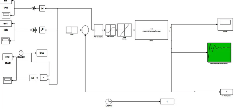
The results of the study are divided into two parts each part presents one type of error (IAE and ISE) as the
performance indices of the system and the comparison between each type of error chosen in the MATLAB program. The block diagram for the complete system using PID controller tuning with PSO is shown in Figure 3.
Figure3: The schematic diagram of DC motor.
ISSN (Print) : 2320 – 3765 ISSN (Online): 2278 – 8875
I
nternational
J
ournal of
A
dvanced
R
esearch in
E
lectrical,
E
lectronics and
I
nstrumentation
E
ngineering
(An ISO 3297: 2007 Certified Organization)
Website: www.ijareeie.com Vol. 6, Issue 12, December 2017
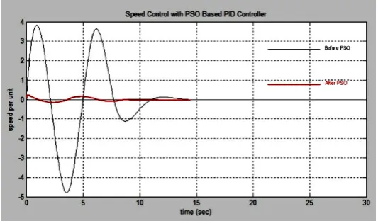
Figure 4: O/P response for PSO with IAE.
Figure5: IAE with PID by PSO.
No. of Iteration Kp Ki Kd Settling time IAE
200 8.9052 6.9817 6.3862 8.6140 25.7162
Table 2: The results of the program using PSO with IAE.
ISSN (Print) : 2320 – 3765 ISSN (Online): 2278 – 8875
I
nternational
J
ournal of
A
dvanced
R
esearch in
E
lectrical,
E
lectronics and
I
nstrumentation
E
ngineering
(An ISO 3297: 2007 Certified Organization)
Website: www.ijareeie.com Vol. 6, Issue 12, December 2017
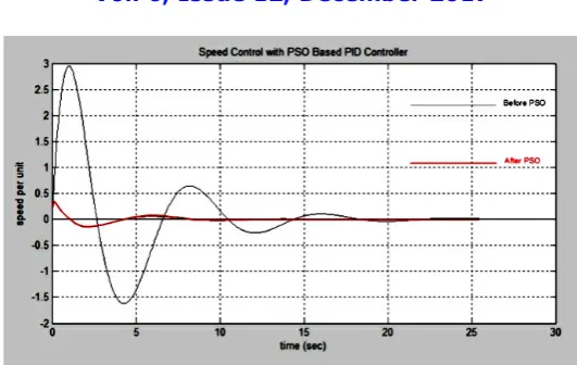
Copyright to IJAREEIE DOI:10.15662/IJAREEIE.2017.0612023 8919 Figure 6: O/P response for PSO with ISE.
Figure 7: ISE with PID by PSO.
No. of Iteration Kp Ki Kd Settling time IAE
200 8.9052 8.4393 4.9187 8.7862 16.1257
Table 3: The results of the program using PSO with ISE.
IV. PREFACE TO ADAPTIVE WEIGHTED PARTICLE SWARM (AWPSO)
ISSN (Print) : 2320 – 3765 ISSN (Online): 2278 – 8875
I
nternational
J
ournal of
A
dvanced
R
esearch in
E
lectrical,
E
lectronics and
I
nstrumentation
E
ngineering
(An ISO 3297: 2007 Certified Organization)
Website: www.ijareeie.com Vol. 6, Issue 12, December 2017
The adaptive weighted PSO is achieved by two terms: inertia weigh (W) and Acceleration factor (A). The inertia weight function is to balance global exploration and local exploration. It controls previous velocities effect on the new velocity. Larger the inertia weight, larger exploration of search space while smaller the inertia weights, the search will be limited and focused on a small region in the search space. The inertia weight formula is as follows which makes w value changesrandomly from Wo to 1 [16-18].
W=Wo + rand (0, 1) (1-Wo)(3)
Particle velocity at ith iteration as follows:
Vi(t) = W. Vi(t-1) + AC1.rand(0,1).(Pbest -X i(t-1)) + AC2.r and(0,1).(gbest -X i(t-1))(4)
Additional term denoted by A called acceleration factor is added in the original velocity equation to improve the swarm search.
The acceleration factor formula as follows: A=A0+i/n(5) Where: n is the number of iteration
As shown in acceleration factor formula that the acceleration term will increase as the number of iterations increases, which will enhance the global search ability at the end of the run and help the algorithm to get far from the local optimum region [19].The constant C1 and C2 represent the weighing of the stochastic acceleration terms that pull each particle towards Pbest and gbest positions. Low values allow particles to roam far from the target region before being tugged back. However, high values result in abrupt movement toward, or past, target regions as explained [20].
The adaptive weighted PSO parameters descriptions are listed below in Table 4.
Parameter Description
Vi(t) Velocity of the particle I at iteration t (m/s) X i(t) Current position of particle I at iteration (m)
d Dimension t Time (s) i Particle number N Number of particles
C1 and C2 Are the constant representing the weighing of the Stochastic acceleration terms that pull each particle towards Pbest and gbest positions
Rand(0,1) Random number obtained from a uniform random distribution
ISSN (Print) : 2320 – 3765 ISSN (Online): 2278 – 8875
I
nternational
J
ournal of
A
dvanced
R
esearch in
E
lectrical,
E
lectronics and
I
nstrumentation
E
ngineering
(An ISO 3297: 2007 Certified Organization)
Website: www.ijareeie.com Vol. 6, Issue 12, December 2017
Copyright to IJAREEIE DOI:10.15662/IJAREEIE.2017.0612023 8921
gbest Global best position (m) W The time-varying inertia weight
Wo Initial positive constant in the interval [0, 1] Ao Initial positive constant in the interval [0.5, 1]
n Number of iterations
Vi(t) Velocity of the particle I at iteration t (m/s)
Table 4: AWPSO parameters description.
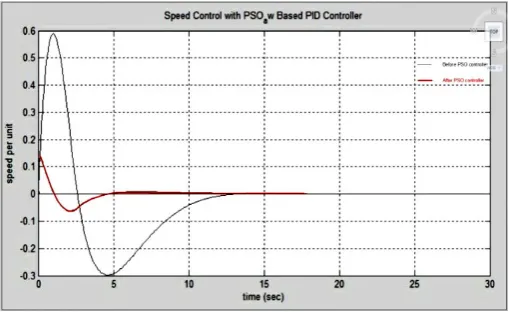
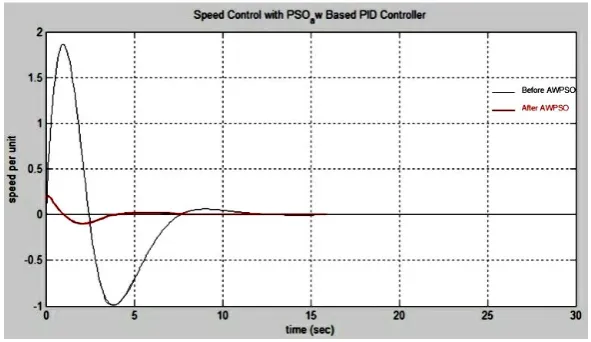
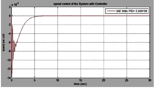
The o/p response for AWPSO with IAE and IAE with PID by AWPSO are shown in Figures 8 and 9. The results of the program using AWPSO with IAE are listed in Table 5.
No. of Iteration Kp Ki Kd Settling time IAE
200 3.8522 1.2415 3.1826 3.7065 0.049159
Table 5: The results of the program using AWPSO with IAE.
The o/p responses for AWPSO with ISE and ISE with PID by AWPSO are shown in Figures10 and 11.The results of the program using AWPSO with ISE are listed in Table6.
The results of the study are divided into two parts each part presents one type of error (IAE and ISE) as the performance indices of the system and the comparison between each type of error chosen in the MATLAB program.
ISSN (Print) : 2320 – 3765 ISSN (Online): 2278 – 8875
I
nternational
J
ournal of
A
dvanced
R
esearch in
E
lectrical,
E
lectronics and
I
nstrumentation
E
ngineering
(An ISO 3297: 2007 Certified Organization)
Website: www.ijareeie.com Vol. 6, Issue 12, December 2017
Twocornertruncationwithonerectangularspaceslotmovedthefrequencyfromlowertohigherbandwiththechangeinreturnofthelos s.Soonebyonecornertruncationprocedurewasdonetowatchtheconductofreturnlosses.Returnlosseschangewasseenafterthetrunc ationofeveryoneofthefourcornersofthepatchandmakingtworectangularopeningsslotsasappearedinFigure4.Theadjustmentinth econductofreturnlossisbecauseofthepresentdispersiononthepatchsurface
(Figure4).ImpactofReturnLossoftheproposedantennabecauseofthespaces/slotsonthepatchB.ReturnLossofProposedAntenna. TheproposedantennawasanalyzedandsimulatedbyutilizingHFSSBetweenthefrequencies2-9GHz.
Figure 9: IAE with PID by AWPSO.
The o/p response for AWPSO with ISE and ISE with PID by AWPSO is shown in Figures10 and 11. Theresults of the program using AWPSO with ISE are listed in Table 6.
ISSN (Print) : 2320 – 3765 ISSN (Online): 2278 – 8875
I
nternational
J
ournal of
A
dvanced
R
esearch in
E
lectrical,
E
lectronics and
I
nstrumentation
E
ngineering
(An ISO 3297: 2007 Certified Organization)
Website: www.ijareeie.com Vol. 6, Issue 12, December 2017
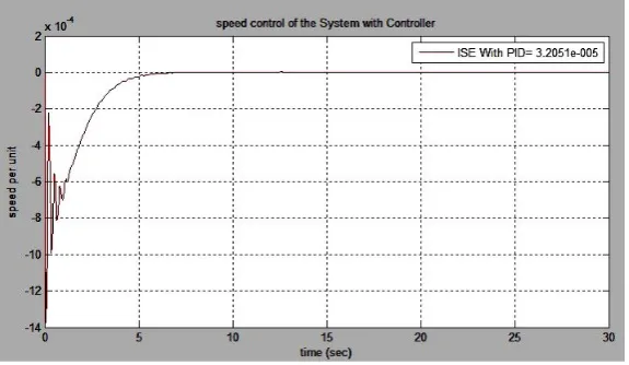
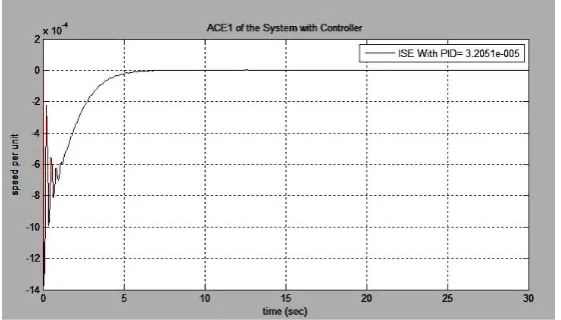
Copyright to IJAREEIE DOI:10.15662/IJAREEIE.2017.0612023 8923 Figure 11: ISE with PID by AWPSO.
Kp Ki Kd Settling time(S) ISE
6.3781 3.9742 4.6605 3.8271 3.2051*e-005
Table 6: The results oftheprogram using AWPSO with ISE.
V. ADAPTIVE ACCELERATION PARTICLE SWARM
New researches have emerged to improve PSO Algorithms, as Time-Varying Acceleration Coefficients (TVAC), where C1 and C2[21-23] change linearly with time, in the way that the cognitive component is reduced while the social component is increased as the search proceeds.
The new approach is destined to change acceleration coefficients exponentially (with inertia weight) in the time, with respect to their minimal and maximal values. The choice of the exponential function is justified by the increasing or decreasing speed of such a function to accelerate the convergence process of the algorithm and to get better search in the exploration space. Furthermore, C1 and C2 vary adaptively according to the fitness value of Gbest and Pbest, becomes: A new approach called Adaptive Acceleration Coefficients based PSO (AACPSO) as explained in to implement the PSO algorithm will be described. A suggestion will be given on how to deal with inertia weight and acceleration factors. The new approach is confident to change acceleration coefficients exponentially (with inertia weight) in the time, with respect to their minimal and maximal values. The choice of the exponential function is justified by the increasing or decreasing speed of such a function to accelerate the convergence process of the algorithm and to get better search in the exploration s pace. Furthermore, C1 and C2 vary adaptively according to the fitness value of Gbest and Pbest.
ISSN (Print) : 2320 – 3765 ISSN (Online): 2278 – 8875
I
nternational
J
ournal of
A
dvanced
R
esearch in
E
lectrical,
E
lectronics and
I
nstrumentation
E
ngineering
(An ISO 3297: 2007 Certified Organization)
Website: www.ijareeie.com Vol. 6, Issue 12, December 2017
2) Step2: Evaluate the fitness function of all particles in the population using the above equations. Find best position Pbest of each particle and update its objective value. Similarly, find the global best position Gbest among all the particles and update its objective value.
3) Step3: If stopping criterion is met, output the Gbest particle and its objective value. Otherwise continue. 4) Step4: Calculate kc coefficient, evaluate the inertia factor and acceleration coefficients according to Equations:
(t) wo*exp *
w w t
(6)
1(t) c10*exp * * (t)
c t kc
(7)
2 c 20*exp * * (t)
c t kc
(8)
So that each particles movement is directly controlled by Gbest and Pbest fitness values. 5) Step5: Update the velocity using Equation
(t 1) (t) (t) (t) (t) (t) (t) (t) (t)
1 1* 2 2*
i i i i
v w v c r pbest x c r Gbest x
(9) and if its new value goes out of range, set it to the boundary value. 6) Step6: Update the position of each particle according to equation
(t 1) (t) (t 1)
i i i
x x v
(10) Check and Go to step 2.
The description of the variable shown in the above equations shown in Table 7.
The results of the study are divided into two parts each part presents one type of error (IAE and ISE) as the performance indices of the system and the comparison between each type of error chosen in the MATLAB program.
The o/p responses for AACPSO with IAE and IAE with PID by AACPSO are shown in Figures12 and 13.The results of the program using AACPSO with IAE is listed in Table 8.
Parameter Description
Vi(t) Velocity of the particle i at iteration t (m/s) X i(t) Current position of particle i at iteration (m) d Dimension
ISSN (Print) : 2320 – 3765 ISSN (Online): 2278 – 8875
I
nternational
J
ournal of
A
dvanced
R
esearch in
E
lectrical,
E
lectronics and
I
nstrumentation
E
ngineering
(An ISO 3297: 2007 Certified Organization)
Website: www.ijareeie.com Vol. 6, Issue 12, December 2017
Copyright to IJAREEIE DOI:10.15662/IJAREEIE.2017.0612023 8925
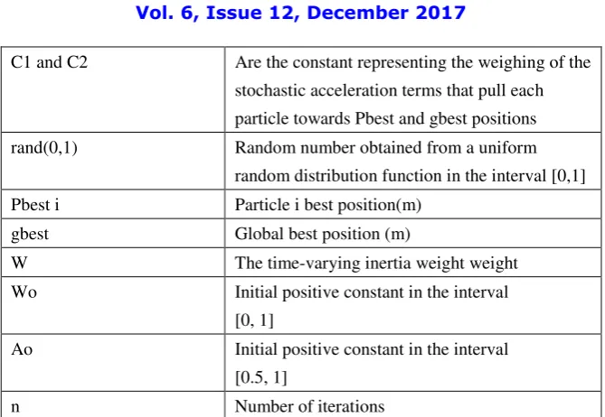
C1 and C2 Are the constant representing the weighing of the stochastic acceleration terms that pull each particle towards Pbest and gbest positions rand(0,1) Random number obtained from a uniform
random distribution function in the interval [0,1] Pbest i Particle i best position(m)
gbest Global best position (m)
W The time-varying inertia weight weight Wo Initial positive constant in the interval
[0, 1]
Ao Initial positive constant in the interval [0.5, 1]
n Number of iterations
Table 7: AACPSO parameters description.
ISSN (Print) : 2320 – 3765 ISSN (Online): 2278 – 8875
I
nternational
J
ournal of
A
dvanced
R
esearch in
E
lectrical,
E
lectronics and
I
nstrumentation
E
ngineering
(An ISO 3297: 2007 Certified Organization)
Website: www.ijareeie.com Vol. 6, Issue 12, December 2017
Figure 13: IAE with PID by AACPSO.
No. of Iteration Kp Ki Kd Settling time IAE
200 1.9333 1.1951 0.4905 2.7028 0.0492
Table 8: The results of the program using AACPSO with IAE.
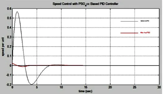
The o/p response for AACPSO with ISE and ISE with PID by AACPSO are shown in Figures 14 and 15.The results of the program using AACPSO with ISE is listed in Table 9.
ISSN (Print) : 2320 – 3765 ISSN (Online): 2278 – 8875
I
nternational
J
ournal of
A
dvanced
R
esearch in
E
lectrical,
E
lectronics and
I
nstrumentation
E
ngineering
(An ISO 3297: 2007 Certified Organization)
Website: www.ijareeie.com Vol. 6, Issue 12, December 2017
Copyright to IJAREEIE DOI:10.15662/IJAREEIE.2017.0612023 8927 Figure 15: ISE with PID by AACPSO.
C11 C22 Kp Ki Kd Settling time ISE
2 2.05 8.099 8.439 4.918 2.616 3.2051* e-005
Table 9: The results of the program using AACPSO with ISE.
VI.MODIFIED ADAPTIVE ACCELERATION PARTICLE SWARM
In this research work, a different scheme for considering C1 (t ) and 2 (t) is proposed. Considering C1 (t) as given in Equation (14) and instead of the Equation (11) the parameter C2 (t) is suggested (for first time in this article) to be as given by: Equation (12):
(t) W Vi(t 1) AC1rand(0,1) (t 1) 2 rand(0,1) (gbest Xi(t 1)
Vi PbestXi AC
(11)
1( )
1 *exp(-
* *
( ))
C t
C o
c t kc t
(12)
ISSN (Print) : 2320 – 3765 ISSN (Online): 2278 – 8875
I
nternational
J
ournal of
A
dvanced
R
esearch in
E
lectrical,
E
lectronics and
I
nstrumentation
E
ngineering
(An ISO 3297: 2007 Certified Organization)
Website: www.ijareeie.com Vol. 6, Issue 12, December 2017
2( )
2 *exp(
* * ( ))
C t
C o
c t kc t
(13)the parameter C2(t) is suggested to be equal[25]:
2( )
1(t)
C t
CT C
(14)A) The Procedure of MAACPSO
The procedure could be summarized as follows: 1) Initialization: PID tuning system.
2) Evaluate the fitness function of all particles in the population using the above equations. Find best position Pbest of each particle and update its objective value. Similarly, find the global best position Gbest among all the particles and update its objective value.
3)If stopping criterion is met, output the Gbest particle and its objective value. Otherwise continue.
4) Calculate kc coefficient, Evaluate the inertia factor and acceleration coefficients according to Equations (6), (7) and (8); and the A0=0.5. So that each particles movement is directly controlled by Gbest and Pbest fitness values.
5) Update the velocity using Equation (9) and if its new value goes out of range, set it to the boundary value. 6) Check and Go to step 2.
The results of the study are divided into two parts each part presents one type of error (IAE and ISE) as the performance indices of the system and the comparison between each type of error chosen in the MATLAB program. CT was studied for the range 0.5 to 6 . Best results were obtained when CT=4.5 [26,27].
ISSN (Print) : 2320 – 3765 ISSN (Online): 2278 – 8875
I
nternational
J
ournal of
A
dvanced
R
esearch in
E
lectrical,
E
lectronics and
I
nstrumentation
E
ngineering
(An ISO 3297: 2007 Certified Organization)
Website: www.ijareeie.com Vol. 6, Issue 12, December 2017
Copyright to IJAREEIE DOI:10.15662/IJAREEIE.2017.0612023 8929 Figure 16: O/P response for MAACPSO with IAE.
Figure 17: IAE with PID by MAACPSO.
Ct Kp Ki Kd Settling time IAE
4.5 8. 9052 0.1250 0.1514 2.4835 0.049159
Table 10: The results of the program using MAACPSO with IAE.
The o/p response for MAACPSO with ISE and ISE with PID by MAACPSO are shown in Figures18 and 19.The results of the program using MAACPSO with ISE is listed in Table 11[28].
Ct Kp Ki Kd Settling time ISE
4.5 3.6333 5 .0825 3.0878 2.5268 3.2051* e-005
ISSN (Print) : 2320 – 3765 ISSN (Online): 2278 – 8875
I
nternational
J
ournal of
A
dvanced
R
esearch in
E
lectrical,
E
lectronics and
I
nstrumentation
E
ngineering
(An ISO 3297: 2007 Certified Organization)
Website: www.ijareeie.com Vol. 6, Issue 12, December 2017
Figure 18: O/P response for MAACPSO with ISE.
Figure19: ISE with PID by MAACPSO.
B) Results in Case of IAE Error
The study of the performance of the PID controller will be compared in case of each intelligent technique (PSO, AWPSO, AACPSO And MAACPSO) PID parameters are shown in Table 12.
Item
Description
PSO AWPSO AACPSO MAACPSO
No. of
Iteration
200 200 200 200
IAE 25.7162 0.049159 0.0492 0.049159
ISSN (Print) : 2320 – 3765 ISSN (Online): 2278 – 8875
I
nternational
J
ournal of
A
dvanced
R
esearch in
E
lectrical,
E
lectronics and
I
nstrumentation
E
ngineering
(An ISO 3297: 2007 Certified Organization)
Website: www.ijareeie.com Vol. 6, Issue 12, December 2017
Copyright to IJAREEIE DOI:10.15662/IJAREEIE.2017.0612023 8931
Kp 8.9052 3.8522 1.9333 8.9052
Ki 6.9817 1.2415 1.1951 0.1250
Kd 6.3862 3.1826 0.4905 0.1514
Table 12: The results of PID controller using (PSO,AWPSO,AACPSO and MAACPSO) with IAE.
C) Results in Case of ISE Error
The study of the performance of the PID controller will be compared in case of each intelligent technique (PSO, AWPSO, AACPSO And MAACPSO) PID parameters are shown in Table 13.
Item
Description
PSO AWPSO AACPSO MAACPSO
No. of Iteration 200 200 200 200
ISE 16.125 7 3.2051*e-0 05 3.2051*e-005 3.2051*e-005
Settling Time 8.7862 3.8271 2.7028 2.5268
Kp 8.0995 6.3781 8.0995 7.0253
Ki 8.4393 3.9742 8.4393 1.2202
Kd 4.9187 4.6605 4.9187 2.3141
Table 13:The results of PID controller using (PSO,AWPSO,AACPSO and MAACPSO) with ISE.
VII.CONCLUSION
The proposed PID with MAACPSO has much faster response than other techniques of PSO(PSO, AACPSO, AWPSO). Because of the results of MAACPSO which is the best results of all previous techniques methods to have a minimum value of IAE error at a small value of settling time.
REFERENCES
1.Franken N, Engelbrecht AP,Particle swarm optimization approaches to coevolve strategies for the iterated prisoner's dilemma,IEEE Transactions on
Evolutionary Computation2005; 562 - 579.
2.Chunkai Z, Hong H, Using PSO algorithm to evolve an optimum input subset for a SVM in time series forecasting, IEEE. International Conference on
Systems. Man and Cybernetics, 2005; 3: 793-3796.
3. RaniaHM, Development of advanced controllers using adaptive weighted PSO algorithm with applications, M.Sc. Thesis, Faculty of Engineering, Cairo
ISSN (Print) : 2320 – 3765 ISSN (Online): 2278 – 8875
I
nternational
J
ournal of
A
dvanced
R
esearch in
E
lectrical,
E
lectronics and
I
nstrumentation
E
ngineering
(An ISO 3297: 2007 Certified Organization)
Website: www.ijareeie.com Vol. 6, Issue 12, December 2017
4. Gaing ZL, A particle swarm optimization approach for optimum design of PID controller in AVR system. IEEE Trans Energy Convers 2004; 19:
384–391.
5. S. Ahmed, Tarek B, et al. Economic Dispatch Resolution using Adaptive Acceleration Coefficients based PSO considering Generator Constraints.
International Conference on Control, Decision and Information Technologies May 2013.
6. Khalifa F, Moustafa HM, et al. The application of evolutionary computational techniques in medium term forecasting accepted for presentation at
MEPCON. Mansoura University, Mansoura,Egypt, 2015.
7. Bahgaat NK, Sayed MI El, et al. Application of Some Modern Techniques in load Frequency Control in Power Systems". In:Chaos Modeling and
Control Systems Design 2015; 581: 163–211.
8. Naglaa KB, El-Sayed MI, et al. Load Frequency Control Based on Evolutionary Techniques in Electrical Power Systems, Advances in Chaos Theory
and Intelligent Control, Studies in Fuzziness and Soft Computing 2016; 337.
9. K Ogata, Modern Control Systems University of Minnesota, Prentice Hall 1987.
10. Gaing ZL, A Particle Swarm Optimization approach for optimum design of PID controller in AVR system” IEEE Transaction on Energy Conversion
2004; 384-391.
11. Al-Hamouz Z, Al-Duwaish H, et al. Particle Swarm-Based Sliding Mode Controller with Chattering Reduction Feature: Application to an AGC
Nonlinear Interconnected Model. Dahran, 2010.
12. Sivanadam SN, Visalakshi P, Multiprocessor using Hybrid Particle swarm optimization with Dynamically Varying inertia. International Journal of
computer science and application 2007:95-106.
14. Gaing ZL, A Particle Swarm Optimization approach for optimum design of PID controller in AVR system. Energy Conversion IEEE Transactions
2004; Vol. 19, No. 2, pp. 384-391, 2004.
15.Sudha KR, Vakula VS, et al. PSO Based Design Of Robust Controller For Two Area Load Frequency Control With Nonlinearities. International
Journal of Engineering Science and Technology 2010; 2: 1311-1324.
16.Soundarrajan A, Sumathi S, Undar “Particle Swarm Optimization Based LFC and AVR of Autonomous Power Generating System”. IAENG
International Journal of Computer Science IJCS, 2010.
17. Panigrahi BK , Pandi VR, et al. Adaptive particle swarm optimization approach for static and dynamic economic load dispatch, Energy Conversion
and Management 2008; 49: 1407–1415.
18. Vlachogiannis JG, Lee KY, et al. Economic Load Dispatch a Comparative Study on Heuristic Optimization Techniques With an Improved
Coordinated Aggregation-Based PSO. IEEE Transactions on Power Systems 2009; 24: 991-1001.
19. Mansour RH, Development of advanced controllers using adaptive weighted PSO algorithm with applications. Faculty of Engineering at Cairo
University, Cairo, Egypt, 2012.
20. Khanesar MA, Teshnehlab M, et al. A Novel Binary Particle Swarm Optimization”, 15th Mediterranean conference on Control & Automation 2007.
21. Astrom KJ, Hagglund T, Revisiting the Ziegler–Nichols step response method for PID control. Journal of Process Control 2004; 14: 635–650.
22. Lim SY, Montakhab M, et al. Economic dispatch of power system using particle swarm optimization with constriction factor. InternationalJournal of
Innovations in Energy Systems and Power 2009; l4: 29-34.
23. Abido MA, Al-Ali NA, Multi-objective differential evolution for optimal power flow, IEEE Transactions on POWERENG, Lisbon, Portugal, March
ISSN (Print) : 2320 – 3765 ISSN (Online): 2278 – 8875
I
nternational
J
ournal of
A
dvanced
R
esearch in
E
lectrical,
E
lectronics and
I
nstrumentation
E
ngineering
(An ISO 3297: 2007 Certified Organization)
Website: www.ijareeie.com Vol. 6, Issue 12, December 2017
Copyright to IJAREEIE DOI:10.15662/IJAREEIE.2017.0612023 8933
24. Bouktir T, Slimani L, Optimal power flow of the algerian electrical network using an ant colony optimization method. Leonardo Journal of Sciences
2005; 43-57.
25. Park JB, Lee KS, et al. A particle swarm optimization for economic dispatch with non-smooth cost functions, IEEE Transactions on Power Systems
2005; 20: 34- 42.
26. Gozde1 H, Cengiz M, et al. Particle swarm optimization based load frequency control in a single area power system. electronics and computers
science. Scientific Bulletin 2008; 2: 1453–1119.
27. Panigrahi BK, Ravikumar Pandi V, et al. Adaptive particle swarm optimization approach for static and dynamic economic load dispatch. Journal of
Energy Conversion and Management 2008; 49: 1407–1415.
28. Coelho LS, Chu-Sheng L, Solving economic load dispatch problems in power systems using chaotic and Gaussian Particle Swarm Optimization