Construction of Three-Dimensional Feature Point Model for
Virtual Assembly System using Visual ID Tags
∗
)
Tatsuya UNIGAME, Tomohiro UMETANI and Yuichi TAMURA
Konan University, 8-9-1 Okamoto, Higashinada, Kobe 658-8501, Japan
(Received 22 November 2012/Accepted 14 June 2013)
This paper proposes a method of developing an object shape model for a virtual assembly system using a combination of visual ID tags and three-dimensional (3D) natural feature points. The object shape model with its real size information is useful in large structures where maintenance robots are used to perform repetitive tasks. We developed the feature-point-based shape model by capturing visual ID tags and the feature points of the image with a monocular camera. The developed model can be used for the detection of the object against a background image and for an estimation of its 3D pose (position and orientation). To estimate the pose of the object using the proposed method, we assigned 3D feature points to the captured image using its scale-invariant feature transform features. The method can be applied to complex background images by using visual ID tags or constructing a feature point model. Our experimental results confirmed the feasibility of the proposed method.
c
2013 The Japan Society of Plasma Science and Nuclear Fusion Research
Keywords: object shape model, visual ID tag, pose estimation, real-world information processing DOI: 10.1585/pfr.8.2406120
1. Introduction
The consistent management of objects and informa-tion about them is crucial to virtual and real assembly plants and to maintenance tasks in large scale indoor struc-tures [1–4]. Useful for this purpose is a three-dimensional (3D) shape model with its attributes of identity, shape, size, and pose (position and orientation). The worker and ma-chine only need a visual system to use it. A method of de-veloping a 3D shape model that uses visual ID tags, which is easier to use than conventional methods, has been pro-posed [5]. However, it is necessary to attach at least one recognition tag to the object when the model is used.
This paper proposes a method of developing an ob-ject shape model for the recognition of obob-jects by means of natural feature points. When using the model, the fea-ture, points that are easy to track in the image sequence detected by the camera without the aid of visual ID tags (Fig. 1). The method can be employed in mobile devices with monocular cameras and in indoor environments such as factories and plants. It is also possible to use it to sim-ulate the assembly of an object. Moreover, the model can be used in applying the augmented reality (AR) technique. The proposed method of developing the model in-volves combining the Scale-Invariant Feature Transform (SIFT) features [6] and the 3D coordinates of the fea-ture points of an object. By the assignment of visual ID tags, this information is used to develop a polyhedral shape model. To recognize an object, the SIFT features of the
author’s e-mail: [email protected], [email protected]
∗)This article is based on the presentation at the 22nd International Toki Conference (ITC22).
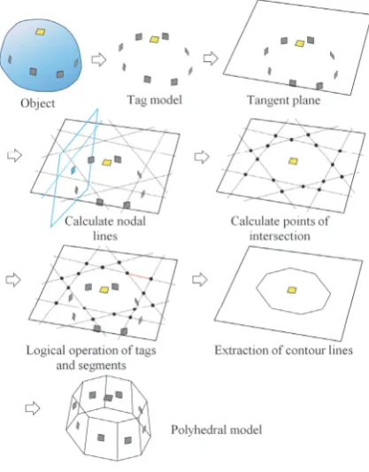
Fig. 1 Illustration of our shape modeling method.
camera image are matched with the image obtained at the time of the modeling. The Pose from Orthography and Scaling with Iterations (POSIT) algorithm [7] is used to estimate the pose of the object.
One of the applications of the proposed method is the virtual assembly system for the maintenance operator, and the teaching system of an automated robot and indus-trial machine for maintenance and assembly tasks by a hu-man operator in the large scale environment. We focus on convex-type objects for modeling and pose estimation to show feasibility of the method. Our experimental testbed is a laboratory room, which is an environment that can construct a prototype system for pose estimation. Our ex-perimental results confirm the feasibility of the proposed method.
c
2. Construction of Shape Model
This section describes our proposed method of devel-oping a shape model that can be used to identify an object. The method involves the building of a polyhedral model of the object by means of visual ID tags assigned to natural feature points of the object.
2.1
Approximate polyhedral modeling using
visual ID tags
We used the visual ID tags illustrated in Fig. 2 to ex-tract points on the image that match those on the cam-era image of the target object and to determine the tan-gent plane of the object. A camera image captured by a monocular camera was used to obtain the geometrically transformed ID tags. The relative position and orientation to the camera were obtained from the transformed image of the ID tags. For the detection of the visual ID tag, we used ARToolKit [8]. ARToolKit is a programming library that uses a Tag-marker to aid the application of the AR technique. Multiple tags that could be detected in a sin-gle image were attached to the target object. The overall positional relationship of the tags was estimated from their local positional relationships.
A tag model of the object was constructed from a set of tag positions. We assumed that tagmhad IDm. Each tagmdefined a frame (or coordinate system)m. The ob-served data of tagmwere the identification of the tag and a homogeneous transformation matrixcTm, which is the transformation from the camera framecto the tag framem
(Fig. 3). We calculatedmTn, which is the relative positional relationship between tagmand tagnand was observed for a particular image as follows:
m
Tn=mTccTn=(cTm)−1cTn. (1) We determined the position of all the tags frommT
n observations. First, the reference frame was set to a tag frame b. The tag model Mn was then calculated using Eq. (2):
Mn=MmmTn. (2) Next, we constructed a polyhedral modelMsusing the tag modelMt. Figure 4 shows the procedure for constructing
Ms. For each segment, the following tasks were performed with respect to all the tags.
Fig. 2 Examples of visual ID tags.
Fig. 3 Observation of tags with a camera.
The edges of the polygon corresponding to the tangent planemwere represented by fm. First, fmwas calculated for every tangent planem. The polygon was calculated us-ing the followus-ing procedure. First, the nodal lines made on the tangent planem by the intersecting tangent plane
n (m n) were obtained. Next, the intersecting points of the nodal lines were calculated, which divided all the nodal lines into multiple segments. Third, the segments be-longing to fmwere determined using Boolean operations. Specifically, if segmentswas included in the polygon as determined from the tagm, we assigned 1 to the segment; otherwise, we assigned 0.
We also assigned 1 to segments that were part of the polygon as a result of the AND operations for the seg-ments. The system left only contours of the polygon and the need to remove the segments inside the polygon. The contour was selected based on whether the nearby points on the sides of the segment were determined to be either inside or outside. The polyhedral modelMs was obtained by placingftat the position of each tag ofMt.
Our modeling method extracts a three-dimensional object region as a polyhedral model. In addition, the method identifies each plane of the object. The minimum number of the visual tags to identify the object is four, if the target object is convex and the object does not have a set of parallel planes. On the other hand, the maximum number of the tags depends on the number of the planes contained on the object. The number of the visual tags can be defined as the number of the planes of the polyhedral model by the user.
This paper focuses on convex-type objects for
Fig. 5 Construction of feature point model.
ing and pose estimation to show feasibility of the method. The construction of the model of the object which has con-cavities will be addressed by a future work.
2.2
Construction of feature point model
After the polyhedral model of the object was obtained, a feature point model was constructed. Figure 5 shows the construction procedure. First, the object image was captured by a camera, from which the feature points of the object were extracted and the tags were detected. We extracted the feature points using SIFT. Since SIFT fea-ture points have feafea-tures that are invariant to rotation and scaling, we identified the feature points using their posi-tions and quantity. Next, we selected the feature points that were included in the polygonal area by projecting the polygonal plane of the detected tagmonto the image plane. The system determined the polygon that included the fea-ture points using the sum of the angles between the feafea-ture points and the vertices of the polygon. If the feature points were inside the polygon, the sum of the angles would be 360◦ or−360◦; otherwise, it would be zero. The system assigned the ID of the tagmto a feature point that was in-side the polygon. The above tasks were performed for all feature points in the image and the appropriate ones were assigned IDs and added to the tagmplane of the polyhedral model.During constructing the feature point model of the ob-ject, many feature points from the captured image can be detected. In this case, several feature points are not used for object identification and pose estimation. In the real application, because of the occlusion of the visible area of the object and the mismatching of the feature points, much more feature points from one appearance of the target ob-ject are needed for obob-ject identification.
Fig. 6 Matching SIFT feature points.
3. Object Pose Estimation using SIFT
Feature Points of the Model
This section describes a method of estimating the pose of the target object using the developed feature point model. The pose of the object is estimated from the corre-sponding feature points of the model and the feature points of the object’s image.
3.1
Finding matching features and noise
re-moval using Random Sample Consensus
To estimate the pose of the target object in a cam-era image, the system finds matching feature points in the model and camera image. Since the matching is subject to error, instances of incorrect matching are removed by Random Sample Consensus (RANSAC) [9]. Figure 6 il-lustrates the process.1. The system finds matching features by means of two-dimensional feature points and camera images ob-tained at the time of generating model, using the k-nearest neighbor (k-nn) method. At this point, the matched points contain outliers.
2. Four pairs of matching features are chosen at random, from which a pair of rectangles is created with corre-sponding vertices. Then,Hi[3×3], which is the per-spective transformation matrix of a two-dimensional (2D) image, is calculated using the pair of rectangles. 3. A perspective projection transformation to the feature
points of the model is performed usingHi.
Fig. 7 Illustration of the POSIT algorithm.
target object.
By repeating steps 2 and 3, the perspective transfor-mation matrix that minimizes the sum of the distances be-tween the coordinates of the transformed points and the coordinates of the feature points of the camera image is determined. Erroneously matched feature points are re-moved by step 4 using the obtained perspective transfor-mation matrix.
3.2
Pose estimation by POSIT
After determining the matching points, the pose of the target object is estimated. Information about the position and orientation of the object is obtained using the POSIT algorithm [7].
Figure 7 is an overview of the POSIT algorithm.
Pi(Xi,Yi,Zi) and pi(xi, yi,zi) respectively identify the fea-ture pointiwith respect to the real world coordinates and the image plane of the camera.−−−→P0Piand−−−→p0piare their re-spective displacements relative to the feature point 0.x,y, andzindicate the coordination frame of the camera. f is the focal length of the camera. i, j, k define the coordi-nation frame of the object. The POSIT algorithm is used to obtain the pose of the object in the image as a rotation matrixRand the translation componentD.
4. Experiment
This section describes the experiment that was per-formed to develop the feature point model and estimate the pose of the target object. We used a USB camera (ELE-COM UCAM-DLS30HSV) to shoot the tags and object. OpenCV, which is an image processing program library, was used to extract the feature points.
4.1
Construction of feature point model
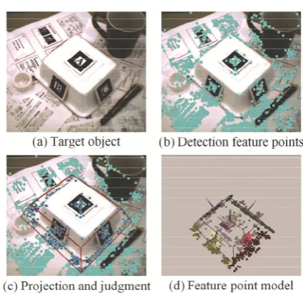
Figure 8 illustrates the process of constructing the model. Figure 8 (a) shows the target object, which is con-vex on all sides. Tag is the square of the one side lengthFig. 8 Construction of three-dimensional shape model.
40 [mm].
Figure 8 (b) shows the results of detecting the tags and extracting the feature points. The light blue points in the image represent the extracted feature points. When us-ing the model, it is necessary to remove the tagged fea-ture points. Figure 8 (c) shows the results of projecting the polygonal area onto the image plane and selecting the fea-ture points. The blue points represent the feafea-ture points within the polygonal area. As shown in Fig. 8 (c), there were projection errors. We consider that this was due to the accumulated errors in constructing the polyhedral model. Figure 8 (d) shows the model constructed with the pro-posed method. The colors of the feature points correspond to those of the surface tag markers.
The experimental results showed that it was possible to project the feature points onto the plane of the model, al-though deviations from the actual positions were observed. One of the reasons of these deviations is the projection er-rors due to inaccurate camera parameters. The tuning of accurate camera parameters by camera calibration will be addressed in a future work.
The many visual ID tags to describe each plane of the object are needed for modeling in order to improve the ac-curacy of pose estimation of the complex-shaped object. The reasonable number of the visual ID tags depends on the shape of the target object; the criterion of the number of the visual ID tags for modeling the object is needed. The criterion of the number of visual ID tags is our future work.
4.2
Estimation of object pose
Fig. 9 Experimental result (simple background).
Fig. 10 Experimental result (complex background).
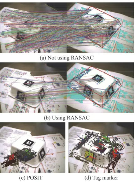
as that in Fig. 8 (c), while that on the left is the camera image of the experiment. Figure 8 (c) is used to illustrate the matching results that should not be used for matching
the 2D image. Figures 9 (b) and 10 (b) show the results ob-tained in the case of using RANSAC. The segments of each figure show the correspondence between the feature points of the model and those of the left image. It can be observed that the erroneously matched features were removed by us-ing RANSAC. Figures 9 (c) and 10 (c) show the results of applying the method of estimating the pose of a target ob-ject by POSIT to the feature point model. Figures 9 (d) and 10 (d) show the results of estimating the pose using a tag marker.
In the experimental results in Fig. 9, there was slight error of rotation, and the error of translation was about 82 [mm]. In Fig. 10, some features were not correctly matched and the estimated pose was very different from the actual pose. One reason for this was that the feature points of the model included the feature points of the back-ground. To solve this problem, a method that extracts only the feature points of the object by means of clustering is required.
If the pose of the target object is significantly diff er-ent from the pose of the object in the image when devel-oping the model, it means that the features were not cor-rectly matched. There are mismatch pair of feature points matching method using only description of SIFT features. A matching method that uses the pattern of feature between the feature points and not only the SIFT features can also be used to improve the estimation accuracy.
5. Conclusion
This paper proposed a method of generating a shape model of an object against a complex background image using visual ID tags and natural feature points, and also estimating the pose of the object. We applied this method to a convex object. Using tag markers, we used feature points to obtain 3D positional information in a monocular camera image. The developed model was larger than the object and included feature points of the background. The estimation error increased if the feature points of the model and those of the background were erroneously matched.
From the experimental results, our future works in-clude the minimization of the projection error and the ob-servation of error when building the model, which will im-prove the accuracy of matching and elimination of changes in the pose and size of the object. The positional relation-ship between feature points when searching for matching points will be utilized for this purpose.
Acknowledgments
This work was supported in part by the JSPS Grants-in-Aid for Scientific Research (#22500114 and #24500288), and MEXT.
[1] T. Umetani, T. Arai, Y. Mae, K. Inoue and T. Maeda, Autom. Constr.15, 774 (2006).
[2] N. Mizuguchi, Y. Tamura, S. Imagawa, A. Sagara and T. Hayashi, Fusion Eng. Des.81, 2755 (2006).
[3] Y. Tamura, N. Mizuguchi, S. Matsumoto and H. Ueki, Proc. 17th Int. Conf. on Artificial Reality and Telexistence, 284
(2007).
[4] Y. Tamura, A. Kageyama, H. Nakamura, N. Mizuguchi and T. Sato, J. Plasma Phys.72, 1065 (2006).
[5] H. Tanaka, T. Yairi and K. Machida, Proc. 2008 IEEE Int. Conf. on SMC, 347 (2008).
[6] D.G. Lowe, Int. J. Comput. Vision60, 91 (2004).
[7] D.F. DeMenthon and L.S. Davis, Int. J. Comput. Vision15, 123 (1995).
[8] H. Kato and M. Billinghurst, Proc. 2nd Int. Workshop on Augmented Reality (1999).