670
LATERATION TECHNIQUE FOR WIRELESS INDOOR
POSITIONING IN SINGLE-STOREY AND MULTI-STOREY
SCENARIOS
1LEE CHIN VUI, 2ROSDIADEE NORDIN
Department of Electrical, Electronic and System Engineering, Faculty of Engineering and Built
Environment, Universiti Kebangsaan Malaysia, Bangi 43600, Selangor, MALAYSIA
Department of Electrical, Electronic and System Engineering, Faculty of Engineering and Built
Environment, Universiti Kebangsaan Malaysia, Bangi 43600, Selangor, MALAYSIA
E-mail: [email protected] , [email protected]
ABSTRACT
The focus of this research is to develop a technique for indoor localization for tracking activity using Wireless Local Area Network (WLAN). The research is conducted by studying the characteristic of the WiFi signal propagation inside a multi-storey building during static condition and compare with walking conditions to compare the accuracy of the tracking technique. The results show the characteristic of the graph pattern from the Received Signal Strength Indicator (RSSI) measurement between static and walking conditions around the considered building area. The result shows the RSSI pattern is statistically anomaly and proven that this technique can be applied for wireless indoor localization applications such as hospitalization, logistic tracking, shopping recommendation and future smart house.
Keywords: Indoor Localization, Lateration, RSSI, Wireless, WLAN,
1. INTRODUCTION
Tracking systems are often used in outdoor activities by using GPS to locate and lead people to the destination they wanted to go. The GPS or mobile service mobile do tracking by putting several earth orbit satellites around the world based on the lateration principle [1]. However, when people travel through the tunnel or closed building area, the GPS signals could not penetrate through buildings and caused signal lost.
Since the GPS unable to be used inside a building, therefore in this research is going to develop a localization technique inside a building using WLAN. This motivates a hope to develop a technique to help people doing tracking activity in a different point of view, especially safety and security factors. This research considers the use of the access point (AP) as a beacon to locate people or things inside the building through its signal propagation characteristics.
Most of the commercial buildings are built more than two levels. Most of the researches on
lateration technique are able to locate a coordinate in a single-storey scenario, or which are the experiments and studies conducted by determining the horizontal coordinate, but not in vertically, which in this case is a multi-floor environment. This research focuses on indoor localization technique based on two scenarios: (i) single-storey and (ii) multi-storey scenario which, is to locate the coordinates horizontally and vertically by using the lateration technique. The research also tends to measure and compare the accuracy in the real time situation with average human walking speed.
2. PROBLEM STATEMENT
Places like shopping malls and hospitals are full with people in every day from day to night. For example, in the hospital, there are many visitors, staffs and patient who travel around in and out from the building. This crowded environment caused the hospital staff hard to track the stubborn patient; especially those require special attention and medication.
671 wavelength unable to penetrate building structures such as wall and ceiling. This motivates the development of an indoor wireless localization technique for tracking activity by using existing WLAN infrastructure which in this case is the Access Point (APs) and WiFi-equipped mobile devices.
3. METHODOLOGY
3.1 Identify Research Area
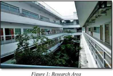
[image:2.595.305.510.260.543.2]This research is conducted at Wing 2 of the administration building of Faculty of Engineering and Built Environment (FEBE), Universiti Kebangsaan Malaysia (UKM) as shown in Figure 1. This building is chosen based on its similarity with other indoor commercial building such as shopping mall and hospitals, which has atrium and multi-storey, with four floor levels. This building also has several additional features like trees, window, metal fencing made it more suitable to investigate the effect of path loss in future study.
Figure 1: Research Area .
3.2 Understanding the Signal Propagation Every building has different patterns and built-in materials such as windows, metal or wooden door, plants, elevator shaft, concrete wall and other static materials. The signal transmitted by the AP is measured with Wifi network scanner software knowing as inSSIDer. The signal propagation study has information related to the static objects that may affect the signal propagation and caused multipath fading around the building. The signal detected by the mobile receiver which in this case is a WiFi laptop is known as RSSI reading and measured in dB.
The obtained RSSI result will be compared against the RSSI measurement take with Ekahau Site Survey for accurate comparison. Ekahau is one of a commercial positioning systems used around the world based on IEEE 802.11 WLAN
infrastructure [1]. This software is able to generate a simulation of WiFi planning based on the signal radiation pattern over the horizontal floor plan. This software also able to construct a simulation scene based on a real scenario, especially the element selection which can define the materials of a building such as doors, wall, and others together with it possible signal loss, dB when the signals propagate through it.
Table 1: Building materials selection available in Ekahau Site Survey software
Material dB Material dB
Unknown 0 Interior Office
Door 4
Bookshelf 2 Marble 6
Brick Wall 10 Solid Wood Door 6
Concrete 12 Steel Fire/Exit
Door 13
Cubicle 1 Steel Rollup Door 11
Dry Wall 3 Thick Window 3
Dry Wall (hollow) 2 Thin Door 2
Elevator Shaft 30 Window 1
Hollow Wood
[image:2.595.91.289.384.517.2]Door 4
Figure 2: Floor plan simulation design
[image:2.595.312.500.575.707.2]672 3.3 Lateration Technique with RSSI
[image:3.595.91.285.216.286.2]A complete tracking system usually consists of the AP devices, the sensor or receiver unit and a computer server that always communicates with the sensors to analyze the signals received from the sensor to locate the coordination of the sensor.
Figure 4: Flowchart of tracking system
This research focuses on the perspective of the sensor or receiver to measure the APs signal propagation characteristic around the building. There are 4 APs used in this research and deployed around the corridor of research area by applying the lateration technique as shown in Figure 4. The lateration technique defines that of the AP signal must cover each other mutually [2], [3], and [4]. When the APs signals propagate, the receiver is able to detect all the APs signals and use as a reference to indicate the location of the receiver. There are four locations to deploy the APs, based on the available power outlet in every storey. The location of the power outlet in every storey is the same and the coordinate of the APs can be found in Figure 2.
The reading is obtained by using a laptop play the role as a receiver to detect and obtain the APs signal strength by using inSSIDer software. The height of the laptop is about 1.3 meter height from the ground by assuming in a real situation, people prefer to put the small size sensor in their shirt pocket which is around 1.3 meter height. The reading is recorded by taking the average RSSI reading around 10 seconds in static positions in every measurement point of the building.
There are eight measurement points in each floor. The measurement points took into account is assumed to be an area where there is a high possibility of people walking along the corridors. Since there are four stories, therefore, there are 128 measuring points total for all 4 APs reading will be recorded in this experiment. Therefore, the total reading need to be taken is 512
readings (4 APs × 18 measuring points × 4 floors) [5].
The obtained RSSI may be compared by computing it using the RSSI formula [6], given
RSSI = - (10n log10 d + A) (1)
n is the propagation constant or an exponent
d is the distance between the receiver and access points
A is the received signal strength in 1 meter distance
Figure5: Measuring points at single story
3.4 Real-Time Measurement
The raw data obtained from the static conditions is analyzed by showing the signal radiation pattern of all 16 APs from 32 measurement points. Moreover, the research is simplified by doing a model of AP deployment planning that can be used by selecting 4 AP points from all 16 available since there are only 4 APs available. To choose the best 4 APs, the condition is these 4 APs must have the same signal radiation pattern by comparing with the signal radiation pattern of overall 16 APs. We will discuss it more detail in the next section. The real-time measurement is conducted by taking the RSSI reading again from a measurement point to another measuring point, in every storey but in walking conditions with average walking speed for young people, 1.4 meters per second [7].
673
4. RESULTS AND ANALYSIS
4.1 Raw RSSI Measurements
[image:4.595.309.505.290.419.2]Figure 6 shows the obtained raw data of RSSI distributions for every measuring point around the building. From the obtained data, we could see how the relation between the signal propagation towards the measuring points. It also shows that, at every measuring point from 1st floor to 4th floor received the same signal patterns of all 16 AP points in the building. This proven that RSSI becomes the dependent value to locate the coordinate of the receiver.
Figure 6: RSSI distribution of all access points (AP) for all measuring points
[image:4.595.92.284.301.419.2]Meaning to say, at every measurement point, the receiver has the possibility to obtain a good, average and weak signal value from the 4 APs as long as the receiver is always in the range of 4 APs used. This also proved that lateration technique can apply at the multi-storey building.
Figure 7: Lateration technique
Lateration technique is illustrated in Figure 7. Each of the APs cannot be placed in the same location. Thus, the 4 APs is deployed in every
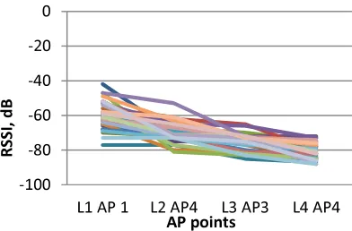
single floor. 4 AP points are chosen among the 16 AP points to deploy around the building, with conditions that all of the four APs have the similar characteristics with the RSSI plot in Figure 6. Figure 1 is the graph pattern of the proposed model for AP point deployment to apply and compare with walking condition, and the graph pattern is relatively similar to the RSSI distribution of the APs as in Fig. 6. Therefore, there are three proposed model is used to compare RSSI reading between the static and walking conditions. The AP deployment location for every Model A, B and C are shown as in Table 2
[image:4.595.304.514.456.556.2]Figure 8: Proposed model for AP deployment
Table 2: Table of Proposed Model Level
Model 1st Floor
2nd Floor 3rd Floor
4th Floor
AP 1 AP 2 AP 3 AP 4
A 1 4 3 2
B 3 4 3 4
C 1 4 3 4
4.2 Measurement comparisons between static and walking
Figure 9: APs Location for Model A
-100 -80 -60 -40 -20 0
1 3 5 7 9 11 13 15
RS
S
I,
d
B
Access Points , AP
-100 -80 -60 -40 -20 0
L1 AP 1 L2 AP4 L3 AP3 L4 AP4
RS
S
I,
d
B
[image:4.595.90.279.545.694.2]674 Figure 10: Comparison on Level 2 at AP4 (L2 AP4)
for Model A
Figure 11: AP Location for Model B
Figure 12: Comparison on Level 2 at AP4 (L2 AP4) for Model B
Figure 13: APs Location for Model C
Figure 14: Comparison on Level 2 at AP4(L2 AP4) for Model C
Figure 9, 11 and 13 shown the location of every APs deployed location for Models A, B and C. Similarity between these 3 models can be seen from sharing a same chosen AP point, which is located on 2nd floor AP4. The pattern of RSSI reading for walking condition, statistics show irregularity compared to the static condition. The result shows the changes of RSSI from point to point around the building, i.e. 1st floor to 4th floor. As shown in the graph, when the receiver migrated from point to point, the RSSI value started to change. The RSSI for walking is taken immediately after reaching a measurement while the RSSI value is taken average in 10 seconds.
5. DISCUSSIONS
675
6. CONCLUDING REMARKS & FUTURE
WORKS
In this research, the lateration technique has been implemented in both single storey and also multi-storey environments. From the measurement results it shows that the lateration technique works not only during static condition, but also can be applied to track a mobile device while moving at the average human walking (1.4 m/s). From the experiment, this localization technique could become one of the parameters to be used in tracking activity and also able to implement in an indoor localization system.
This research was conducted by using four AP devices due to the limited supplies and sources. However, the result shows this technique is able to locate the coordinate in horizontally and vertically and also proven that this technique is helpful and can be applied in future tracking applications, such as children and patient movement to ensure their safety.
Essentially, the location information from the proposed lateration technique can be combined with context information for potential commercial application, such as parking and dining
recommendation in an indoor or building environment
7. ACKNOWLEDGEMENTS
This work was supported by the Malaysia’s Ministry of Science, Technology and Innovation (MOSTI), under the grant ref: 01-01-02-SF0788
REFERENCES:
[1] Phani K. Sagiraju, Praveen Gali, David Akopian, and G. V. S. Raju. “Enhancing Security in Wireless Networks Using Positioning Techniques," IEEE International Conference on System of Systems Engineering, 2007 (SoSE '07), 2007.
[2] Azadeh Kushki, Konstantinos N. Plataniotis, and Anastasios N. Venetsanooulos. “Principles and Applications in Location-Based Services," Ch. 3 Positioning Techniques, Cambridge University Press, 2012, pp 30-41.
[3] Azadeh Kushki, Konstantinos N. Plataniotis, and Anastasios N. Venetsanooulos. “Principles and Applications in Location-Based Services," Ch. 5 Positioning in Wireless Local Area
Network, Cambridge University Press, 2012, pp 55-67.
[4] Zeev Weissman, Indoor Location (White Paper), Tadlys Ltd., 2004.
[5] Chuan-Chin Pu, Chuan-Hsian Pu and Hoon-Jae Lee, “Indoor Location Tracking Using Received Signal Strength Indicator, Emerging Communications for Wireless Sensor Networks," Emerging Communications for Wireless Sensor Networks, 2011.
[6] Erin-Ee-Lin Lau, Boon-Giin Lee, Seung-Chul Lee and Wan-Young Chung, “Enhanced RSSI-Based high accuracy real-time user location tracking system for indoor and outdoor environment”, Proceedings of the 2007 International Conference on Convergence Information Technology, 2007.
[7] TranSafety (1997, October 1), “Study Compares Older and Younger Pedestrian Walking Speeds"
[Online]. Available: