Abstract— This paper presents the coordination of PSS and POD in a S MIB power system equipped with TCS C. S ome effective controller using PS S and POD schemes were proposed to improve power system stability. These controllers produced supplementary signals, the PS S output signal for machine and the POD’s for TCSC. A two stage lead lag compensator scheme was considered in the PS S structure. A new controller design, linear optimal control associated with modal control schemes, is proposed in both PS S and POD design. By sele cting the weighting matrix Q in conjunction with the close loop pole shifting, the proposed modal optimal control has been formulated. The GA method was used to determine the parameter controllers for both PS S and POD. The dynamic and stability of power system with proposed controllers was investigated by using small disturbance to power system, 20% load variation. S imulation results show that the presence of TCS C in power system network provided by PS S and POD controller is very potential to improve system stability. A 45% of overshoot reduction could be reached, it is obtained significantly settling time shorter, although the MO POD shorter only 16% than PS S ones. The dominant eigenvalues shift to the more stable area, the real part of new eigenvalues approach their threshold -0.1. This result indicates that the proposed modal optimal control has a good performance. S imulation results also revealed that the role of POD controller is more dominant than the PS S , however both PS S and TCS C POD controller simultaneously present a positive interaction.
Index Term— GA, modal optimal control, power system stability, S MIB, TCS C
I. INT RODUCT ION
Recent developments of power electronics result in the use of flexible alternating current transmission system (FACTS) devices in power system. FACTS devices have the ability to increase power system operation flexibility and
controllability, system stability and utilization of existing power systems [1]. One of the FACTS device is thyristor controlled series capacitor (TCSC). A TCSC is consists of a capacitor and a thyristor controlled reactor (TCR).
TCSC is generally installed in long transmission line of a power system. Some roles of a TCSC are scheduling power
Sasongko Pramono Hadi is with the Department of Electrical Engineering and Information T echnology, Faculty of Engineering, Gadjah Mada
University, Yogyakarta, Indonesia. [email protected] Hatta Imaduddien Wiennetou is graduate student of T he Department of Electrical Engineering and Information T echnology, Faculty of Engineering,
Gadjah Mada University, Yogyakarta, Indonesia.
Rian Fatah Mochamad is graduate student of T he Department of Electrical Engineering and Information T echnology, Faculty of Engineering, Gadjah
flow, decreasing unsymmetrical components, reducing net loss, providing voltage support, limiting short-circuit currents, damping the power oscillation; and enhancing transient stability [2], [3]. The basis of TCSC’s functions is the ability to give inductive or capacitive reactance to transmission line.
Load changing at power system could induce low frequency oscillations. These oscillations may sustain and grow to cause loss of synchronization between generators. Power system stabilizer (PSS) has been used to damp out oscillations in recent years. The problem is this device may not give adequate damping. In order to achieve an optimal small disturbance performance, the coordination between PSS and TCSC is needed [2].
Recent studies of TCSC show that installation of TCSC in transmission line could enhance transient and oscillatory stability [1], [2]. Additional control signal for TCSC has been developed and applied to improve TCSC performance. This additional control signal is called power oscillation damping (POD). Some studies represent that using POD could improve oscillations damping and enhance power system stability [2]. Different methods have been applied to control PSS and POD. Methods such as lead-lag compensation and PID controller have been studied and reported in several papers. Panda, et al [5] compares lead-lag compensation and PID controller method at different disturbances. Simulation results show that lead-lag compensation is a better method. Another studies also represent that lead lag compensation method gives better oscillations damping and system stability in power system [2], [3], [5], [6]. The problem to devise PSS and TCSC controller parameter is a complex exercise. Some paper used conventional techniques such as eigenvalue assignment, mathematical programming, gradient procedure for optimization, and modern control theory to devise PSS and TCSC controller. The problem is conventional techniques requires heavy computation burden and time consuming for large power system [5]. Recently, heuristic method, especially genetic algorithm (GA), is very popular to design PSS and TCSC controller. The reason behind the popularity of GA is its advantages. The robustness of GA in finding optimal solution and ability to provide a near optimal solution close to a global minimum is one of the advantage of GA. GA uses multiple point instead of single point to search optimal solution, so it convergence faster [8]. Previous studies show the effectiveness of GA to design the controller. The investigation result an improvement of oscillation damping and power system stability [5], [7-9]. Another heuristic
TCSC Power Oscillation Damping and PSS
Design Using Genetic Algorithm Modal
Optimal Control
simulated annealing, etc. have been investigated to get better performance index [10], [11]. These previous studies show that designing TCSC controller is always interesting and needed to improve power system stability.
Linear optimal control (LOC) is a method of control where the system controlled is described in linear state equations. The control is designed by minimizing a function of both state deviations and control effort. The main characteristic of the application of optimal control is the determination of weighting matrix Q and R. Supposed R is relatively constant, the objective function should be formulated by selection of matrix Q. The element of matrix Q represent the weight of certain state variable, when the weight of state variable are known, the optimal control can be determined. The optimal control will modify the system dynamic characteristic, the pole (eigenvalue) of this close loop system should be represent a better system dynamic response, this technique namely modal optimal (MO) control.
The main objective of this study is to investigate the effectiveness of damping function of TCSC in single machine infinite bus (SMIB) power system, by applying: lead-lag compensation Power System Stabilizer (lead-lag PSS), LOC based POD (LOC POD) and a new controller design scheme modal optimal control POD (MO POD). GA is used to design PSS controller parameter and weighting matrix Q of LOC and MO.
II. POWER SYST EM MODEL AND CONT ROLLER DESIGN A. System Configuration
A SMIB power system with a TCSC shown in Fig. 1 is considered in this study. The generator is equipped with a PSS. XT and XL represent the transformer and the transmission
line reactance respectively. Generator terminal and infinite bus voltage is represented by VT and VB respectively.
Components of a TCSC are a capacitor and a TCR. XC and
XL represent the reactance of capacitor and inductor
respectively. T1 and T2 are a bidirectional thyristor. The power
system dynamic model will be developed according to this system configuration [4].
Fig. 1. SMIB power system with T CSC
B. System Dynamic Model
The non-linear equations of the SMIB with TCSC are first formulated. The equations are linearised to obtain power system model used.
The non-linear equations
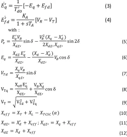
The non linear equations of the SMIB with TCSC are [5] :
̇
(1)
̇
(2)
̇
(3)
̇
(4)
with : (5)
(6)
(7)
(8)
√ (9)
(10)
; (11)
(12)
Linearised model The design of power system controller, such as PSS and POD, has been carried out using linearised model. Linearising the model of SMIB with TCSC represented by equations (1-4) around an operating point of the power system will produce a linearised model of power system. By neglecting the internal resistance and sub-transient process of the generator, and when the function of governor is neglected linearizing equations (1-4) gives the system equation in the form of vectors and matrices [5] : ̇ (13)
̇ (14)
̇ (15)
̇ ( ) (16)
with, ⁄ ⁄ ⁄ (17)
⁄ ⁄ ⁄ (18)
⁄ ⁄ ⁄ (19)
[ ̇̇
̇ ̇ ]
[
] [
]
(20)
[
] [
]
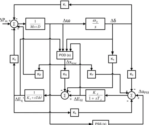
Fig. 2 shows block diagram of the system using proposed method. The proposed method is based on LOC. Input of POD not only rotor speed deviation ( ), but also rotor angular deviation ( ), armature voltage ( ), and internal voltage ( ).
Fig. 2. Linearised model of Phillips-Heffron power system with proposed method
C. Controllers Design
To improve the system stability, the control signal PSS is designed using speed deviation signal Δω as feedback of PSS to produce supplementary signal as control signal. This supplementary signal is fed into excitation system (for electrical loop in machine model). The control signals POD are designed by LOC based method using state v ariable, namely deviation of: rotor angle, angular speed, internal voltage, and armature voltage, to produce supplementary signals . These supplementary signals are fed into TCSC. The control parameter for both PSS and POD are calculated using GA.
PSS design
In study of dynamics power system, common designs for PSS are lag compensation and PI [9]. In this study, lead-lag compensation is used.It consists of a gain, a washout, and a two stage phase compensation block as shown in Fig. 3. Δω
is used as the input of this controller, and the output will give an additional signal to excitation system.
Fig. 3. T wo stage PSS
Gain of PSS (KP SS) will multiply the amplitude of Δω.
Washout block has a function as a high pass filter that will eliminate steady state bias at output signal. Washout parameter, TW, is chosen at 10 s [12]. Two stage phase
compensation block is used to compensate lead or lag phase of the transmission. However, most of transmission system has a lag phase because the inductive reactance is more dominant than the resistance and hence the compensation is lead compensation generally [1]. The compensation of two stage phase block is determined by the time constants T1, T2, T3, and
T4. In this study, GA is used to choose the time constant and
KP SS. Moreover, a more stable system can be achieved by
designing eigenvalue to lie in lefter handside of s plane. This design can be achieved by manipulating fitness function in GA to produce desired eigenvalue [13].
LOC POD design
A general design of POD for TCSC is a lead -lag compensation. Based on equation (20), control design of POD could be designed using LOC scheme to produce a supplementary control signal [13].
Mathematical expression of LOC can be written as follows [13]:
Given a linear system state equation as :
̇ = Ax + Bu (21)
Determine the control signal u:
u = - Kx (22)
where K is state variable feedback control matrix, by minimizing the performance index J, representing cost function in the quadratic form:
J =
∫
TQ x + u
TR u)
dt
(23)
Q is the weighting matrix of the state variable deviations and R that of the control effort. Both Q and R, in the most cases are chosen as diagonal matrices. By minimizing Hamiltonian H related to the Lagrangian, the control optimal can be expressed as follows:
u = - (R
-1B
TP) x
(24)in which P must satisfy the Riccati equation:
A
TP + P A – P B R
-1B
TP + Q = 0
(25)satisfy the desired requirements. A method based on modal analysis could be applied, the selection of Q is taken
incorporate with the desired eigenvalue locus. By shifting the dominant eigenvalue to left hand side of s plane in certain damping ratio, variations of Q are accomplished that guarantee the better control by Riccati matrix equation solution.
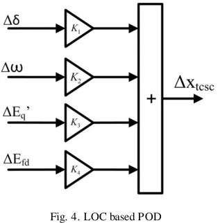
The structure of POD using LOC scheme is s hown in Fig. 4. Based on LOC scheme, GA will be used to find K1, K2, K3,
and K4.
Fig. 4. LOC based POD
III. MODALOPTIM ALPODDESIGNUSINGGENETIC ALGORITHM
A. Genetic Algorithm
GA is an optimization technique based on natural selection and natural genetics. GA consists of several individuals that representing a solution for the problem. At the beginning, GA initiate some random value for each individual. GA will maintain some individuals that have capacity as solution candidate and repeatedly modifies them. At each iteration, GA will get new individuals that could be better or worse. Individual with better solution will be maintained and replaced the old one. The iteration will be stopped after hit the stopping criteria such as maximum generation, stall generation, maximum time, or minimum tolerance. Individual at last iteration is expected to be the best solution. Iteration in GA , called generation, has a cyclic process as follows :
Evaluation of each individual using fitness function. The population undergoes a reproduction to get new individuals called offspring. A couple of individuals will be a parents through a selection. The higher the fitness, the bigger the chance to be the parents.
Offspring could be obtained by genetic operators such as crossover and mutation. Crossover will choose a pair of parents and exchange a part of parents A by a part of parents B. Mutation is a process of changing a random bit of an individual.
The last part of the iteration is elitisme. In this part, the new individual will be compared with the old one. The better one will be maintained while the other will be erased.
Iteration process of GA could be presented as a flowchart. Fig. 5 show the flowchart of GA.
Fig. 5. Genetic algorithm’s flowchart
B. Selection Q using GA for modal control
Fig. 6. Modal optimal flowchart
Using GA, the formulation of modal optimal control design become:
Find the control u, that minimize the objective function:
J
1=
∫
TQ x + u
TR u)
dt
(26) By selecting Q in order to minimizeJ
2= Σ (σ
0– σ
i)
2, for σ
i≥ σ
0(27)
J
3= Σ (ξ
0– ξ
i)
2(28)
Subject to:
a. System dynamics constraint
̇ = Ax + Bu
b. Eigenvalue locus constraint
Fig. 7. Region of eigenvalue for J2
σi is the real part of the i-th eigenvalue and σ0 is a
chosen threshold. The condition σi ≤ σ0 is aimed to
evaluate J2 to consider only the unstable or poorly
damped ones [14].
c. Damping ratio constraint
Fig. 8. Region of eigenvalue for J3
Where ξi is the damping ratio of the i-th eigenvalue.
The condition ξi ≥ ξ0 is aimed to minimize the
oscillation [14].
IV. NUM ERICALSIM ULATION
A. System under Study
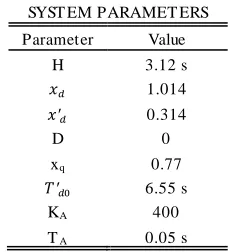
System configuration of this study was as shown in Fig. 1. The parameter data of system component is presented in TABLE I as follows:
TABLE I SYST EM PARAMET ERS
Parameter Value
H 3.12 s
1.014
0.314
D 0
xq 0.77
6.55 s
KA 400
TA 0.05 s
Transmission lines: Ra= 0; XT= 0,07 pu; XL = 0,325 pu. TCSC: Xc = 0,21 pu; Xp = 0,0525 pu; α = 1600.
Suppose the operating condition .
B. Simulation Result and Discussion
Purposed method in this paper was investigated based on eigenvalue analysis and the system dynamic response against disturbances. A 0.2 pu increment in electrical power (Pe) is
given to the system as disturbance. There are three scenarios simulated to know more about the effects of purposed method, they are:
1. Neither PSS nor POD 2. With PSS only
3. With both PSS and MO POD
System without PSS and POD
To evaluate system in normal condition, simulation in SMIB is performed. Using system parameter as shown in Error! Reference source not found.II, and disturbance in the form of a 0.2 pu increment in Pe, the dynamic response of the
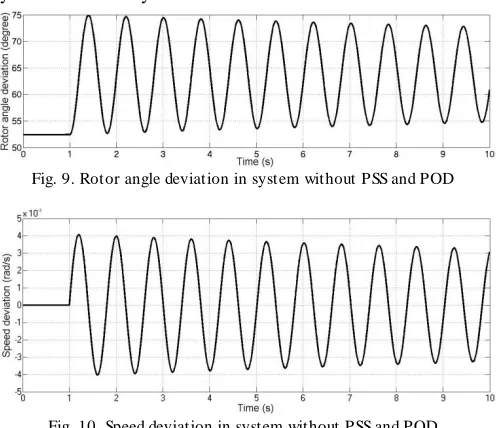
generator will be known. System without POD and PSS is simulated and its results are shown in Fig. 9 and Fig. 10. The first swing of rotor angle reaches 75°, the steady state converges to 64° (11° overshoot). Rotor angle deviation ( ) and speed deviation ( ) response is going toward steady state, but their settling time are still not known though the simulation has run for 10 s. A long s ettling time can lead the system to loss of synchronization.
Fig. 9. Rotor angle deviation in system without PSS and POD
Fig. 10. Speed deviation in system without PSS and POD
PSS controller performance
PSS is used to enhance dynamic respons es performance. Performance of PSS depends on its parameters. Appropriate PSS parameters are needed to ensure that PSS will enhance dynamic responses performance. GA is used to choose PSS parameters by minimizing fitness function expressed in equation (27) and (28). These fitness functions are expected to make system’s eigenvalues to shift to the further left hand side of s plane with certain damping ratio. The chosen real part threshold σ0 is – 0.1, the damping ratio ξ0 is 0.1. TABLE
IIError! Reference source not found. shows PSS parameters that GA found out.
Using increment of Pe as disturbance, the performance of
system with PSS is investigated. Fig. 11 and Fig. 12 are the results of the simulation that show ( ) and ( ) of the generator respectively. Each figure consists of two responses with different operating conditions. The first condition is a condition where there is neither PSS nor LOC POD installed, and the second one is the system with PSS only.
Based on Fig. 11 and Fig. 12, the dynamic response of system with PSS is better than system without PSS. System with PSS gives better oscillation indicated by lower first swing (71°) and faster settling time (3s).
TABLE II PSS PARAMET ERS
KPSS T1(s) T2(s) T3(s) T4(s)
2.4602 3.2038 2.4579 3.4040 2.0260
Fig. 11 Rotor angle deviation in system with PSS, but without POD
Fig. 12 Speed deviation in system with PSS, but without POD
MO POD control performance
Based from result in Fig. 11 and Fig. 12, we want to increase the stability of the system by using MO method to process input signal for POD.
This subsection aims to show the role of MO POD in damping the oscillation of system dynamic response following a disturbance, where the weighting matrix Q in LOC formula are selected based on modal control. Using multi objective GA, optimal parameter for weighting matrix then searched. From n-th iteration, the optimal matrix shown are in TABLE IIIError! Reference source not found..
TABLE III MO POD PARAMET ERS
-0.0799 8.8890 0.3698 0.1122
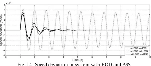
Fig. 13. Rotor angle deviation in system with POD and PSS
Fig. 14. Speed deviation in system with POD and PSS
Fig. 13 and Fig. 14 illustrate the effect of the three type of condition: without PSS and POD, with PSS only, and with PSS and MO POD scheme. The rotor angle dynamics and the speed deviation as depicted in Fig. 13 and Fig. 14 show that damping function MO POD (first swing 70° and settling time 2.5s) is more significant than the PSS’s one. It is also shown that the synergy between PSS and POD has been achieved; the system responses (with both PSS and MO POD) have the best damping, and is more effective than PSS only.
TABLE IV EIGENVALUE LOCI
No POD With MO POD
-10,0061 + 20,1916i
-10,0061 – 20,1916i -0,0323 + 7,8079i -0,0323 – 7,8079i
-1.2739e+003
-0.0722 + 8.5664i -0.0722 - 8.5664i
-0.9502
Table IV shows how the dominant eigenvalues shift to the more stable area, the real part new eigenvalues (-0.0722) close to their threshold -0.1. This result indicates that the proposed modal optimal control has a good performance.
V. CONCLUSION AND FUT URE RESEARCH
GA has been proved as effective solution of optimization problems. This paper investigates a proposed control scheme where PSS using lead-lag compensation and POD using LOC. GA could be used to design MO POD by selecting the weighting matrix Q in order to shift the dominant eigenvalue to the further left side. This new design has been tested with disturbance in the form of increment electrical power.
The simulation compared three different conditions, without PSS and POD, with PSS only, and with PSS and MO POD scheme. The simulation results show that system with PSS and MO POD has the best oscillation damping. Its overshoot is lower and its settling time is faster than the others. Applying PSS and modal optimal control could give a reduction in
settling time (16%) as well as in response overshoot (45%) than system with PSS only.
The dominant eigenvalues shift and approach their real part threshold -0.1, the proposed modal optimal control has a good performance. Both PSS and TCSC POD controller simultaneously present a positive interaction. Shifting dominant eigenvalues in great increment is not recommended, it could lead to non-linearity conditions.
REFERENCES
[1] Narain G. Hingorani and Laszlo Gyugyi, Understanding FACTS: Concepts and Technology of Flexible AC Transm ission System s. NewYork: IEEE Press, 2000.
[2] S.V. Heidari, M. Sedighizadeh, M. Ahmadzadeh, and S. Mohammadzadeh, "Optimal Coordination of PSS and T CSC for Improving of Dynamic Stability in Power Systems Using Genetic Algorithm," Canadian Journal on Electrical and Electronics Engineering, vol. 2, no. 5, 2011.
[3] Sasongko P. Hadi, "Dynamic Modelling and Damping Function of GUPFC in Multi-Machine Power System," The Journal for Technology and Science IPTEK, vol. 22, no. 4, pp. 205-213, November 2011. [4] Sidhartha Panda and N. P. Padhy, "Comparison of Particle Swarm
Optimization and Genetic Algorithm for T CSC-based Controller Design," World Academy of Science, Engineering and Technology, vol. 27, 2007.
[5] Sidhartha Panda, R.N. Patel, and N.P. Padhy, "Power System Stability Improvement by T CSC Controller Employing a Multi-Objective Genetic Algorithm Approach," International Journal of Electrical and Computer Engineering, vol. 1, no. 7, 2006.
[6] Sidhartha Panda and N.P. Padhy, "Power System with PSS and FACT S Controller: Modelling, Simulation and Simultaneous T uning Employing Genetic Algorithm," International Journal of Electrical and Electronics Engineering, vol. 1, no. 1, 2007.
[7] Shoorangiz Shams Shamsabad Farahani, Mehdi Nikzad, Mohammad Bigdeli T abar, Mehdi Ghasemi Naraghi, and Ali and Javadian, "Dynamic Stability Enhancement and Voltage Support Using UPFC T uned Genetic Algorithms in a Multimachine Environment," International Journal of the Physical Sciences, vol. 6, no. 22, pp. 5273-5280, October 2011. [8] Sidhartha Panda, N.P. Padhy, and R.N. Patel, "Genetically Optimized T CSC Controller for T ransient Stability Improvement," International Journal of Computer and Information Engineering, vol. 1, no. 1, 2007. [9] Sidhartha Panda and N. P. Padhy, "T hyristor Controlled Series Compensator-based Controller Design Employing Genetic Algorithm: A Comparative Study," International Journal of Electrical and Com puter Engineering, vol. 2, no. 9, 2007.
[10] Ali Misaghi, Said Hoghoughi Isfahani, Abbas Kargar, Abjadi, and Navid Reza, "Increasing the Stability of Power Systems by Simultaneous Design of PSS and T CSC through the PSO T echnique," Journal of Basic and Applied Scientific Research, vol. 1, no. 10, pp. 1535-1540, 2011. [11] M.A. Abido, "Pole Placement T echnique for PSS and T CSC-based Stabilizer Design Using Simulated Annealing," Electrical Power and Energy System s 22 (2000) 543–554, vol. 22, pp. 543-554, 2000. [12] K.R. Padiyar, Power System Dinamics Stability and Control. Hyderabad:
BS Publication , 2008.
[13] Sasongko P. Hadi, M. T alaat, and R. Moret, "More Exact Method for Determining the Optimal Control Weighting Matrices," in IASTED Interntl Conf on Electrical Power System, Paris, 1987.
[14] Abolfazl Jalilvand, Amin Safari, and Reza Aghmasheh, "Design of State Feedback Stabilizer for Multi Machine Power System Using PSO Algorithm," in 12th IEEE International Multitopic Conference, Zanzan, Iran, 2008, pp. 2-3.
Doctoral degree in 1985 and 1988 respectively, in Electrical Engineering, with research subject: Power System Adaptive Control, from T he Institute Nationale Polytechnique de Grenoble (INPG), France.
Hatta Imaduddien Wiennetou is graduate student of T he Department of Electrical Engineering and Information T echnology, Faculty of Engineering, Gadjah Mada University, Yogyakarta, Indonesia. He was born in Cilacap, April 16, 1991. In 2012, he received Bachelor degree in Electrical Engineering, Gadjah Mada University, Yogyakarta, Indonesia. His interest of research is power system dynamics and stability.