Abstract— Describes how to compute the optimal extension time that will add to the fixed time control system. The system has been developed to simulate of an isolated traffic junction based on fuzzy logic. By using MATLAB (Fuzzy Logic Toolbox) we also show the simulation and the results obtained from the system. A comparison can be made between different fuzzy logic controller algorithms and a conventional fixed-time controller. S imulation results show that the fuzzy logic controller has better performance and is more cost effective.
1. INTRODUCTION
One of the main features of modern cities is the permanent growth of population in a relatively small area. The consequence of this fact is the increase in the number of cars and also the necessity of movement and transport of people and goods in urban city networks.
The monitoring and control of city traffic is becoming a major problem in many countries. Different measures are applied for elimination of unwanted consequences of intensive development of modern cities. Some of them are, for instance, the land use planning, the improvement of traffic control, etc. Significant attention is paid just to the improvement of the automatic traffic control systems. The reason for that is the fact that this measure doesn‟t imply significant changes of infrastructure. A considerable amount of work has been done on the problem of modeling and controlling traffic junctions. Although the major problem in cities concerns sets of intersections (not individual ones), any approach to this problem should also include a sufficient description of the events occurring in any individual intersection in the linked or disjoint system under study . In all the cities in the world, the registration of new vehicles each year increased by about twenty percent. This increment is rather than alarming and even with the development of the new roads other measures have to be stepped up and introduced as quickly as possible. It is understandable that automatic control systems should relieve humans from manual control; however, such automatic system does not work well in many circumstances especially during oversaturated or unusual load conditions which could be due to limitations of the algorithms or sensing devices. In this respect manual control seems to be better due to the intelligence of the humans in understanding the traffic conditions at the respective junctions.
In this paper we discuss the implementation of an intelligent traffic lights control system using fuzzy logic technology which has the capability of mimicking human intelligence for controlling traffic lights. Software based on MATLAB has been developed to simulate an isolated traffic junction. Fuzzy logic technology allows the implementation of real-life rules similar to the way humans would think. For example, humans would think in the following way to control traffic situation at a certain junction: “if the traffic is heavier on the north or south lanes and the traffic on the west or east lanes is less, then the traffic lights should stay green longer for the north and south lanes”. Such rules can now be easily accommodated in the fuzzy logic controller.
2. OVERVIEWOFTRAFFICLIGHT
A significant development of traffic control systems using traffic lights has been achieved since the first traffic controller was installed in London in 1868. Starting from an isolated signalized intersection, the area covered by a traffic control system extended to a series of signalized intersections along an artery (“green wave”) out to street networks with several hundred signalized intersections (“area traffic control systems”). The first green wave was realized in Salt Lake City in 1918, and the first area traffic control was introduced in Toronto in 1960. Traffic control equipment has followed technology development. At the very beginning, traffic control had been performed by electromechanical devices. Then, semiconductor-based controllers were introduced, and nowadays microprocessor-based controllers are used in traffic control systems. The development of area traffic control systems, especially since 1960, has led to introduction of other equipment in traffic control systems, such as computers, telecommunication devices, vehicle detectors, etc.
Traffic control strategies have also improved since the installation of the first traffic controller. The strategies can be classified. The most important strategies are as follows:
Control the Extension Time of Traffic Light in
Single Junction by Using Fuzzy Logic
1- Fixed-time (FT) strategies. The control (signal plan) is calculated in advance, using statistical data.
1- Real-time (RT) strategies. The real-time data about traffic processes are used to determine control or its modification.
The first type of control uses a preset cycle time to change the lights. The other type of control combines preset cycle time with proximity sensors which can activate a change in the cycle time or the lights. The general structure of the present traffic control is shows in Fig. 1. The main control measure in urban road networks is the traffic lights at intersections. Traffic lights, besides ensuring the safety of road crossings, may also help in the minimization of the total time spent by all the vehicles in the network, provided that an optimal control strategy is applied.
3. FUZZY LOGIC CONTROL SYSTEM
Fuzzy logic traffic lights control is an alternative to the present conventional traffic lights control which can be used for a wider array of traffic patterns at an intersection.A fuzzy logic controlled traffic light uses sensors that count cars instead of proximity sensors which only indicate the presence of cars [5].
This provides the controller with traffic densities in the lanes and allows a better assessment of changing traffic patterns. The general structure of a fuzzy traffic lights control system is illustrated as in Fig. 2. There are two electromagnetic sensors placed on the road for each lane. The first sensor behind each traffic light counts the number of cars passing the traffic lights, and the second sensor which is located behind the first sensor counts the number of cars coming to the intersection at distance D from the lights.
The number of cars between the traffic lights is determined by the difference of the reading between the two sensors. The distance between the two sensors D, is determined accordingly following the traffic flow pattern at that particular intersection. Then to determine the density of the other lanes the value of D added to sensors values that gets the number of cars changed their path to the left or to the right of the specified lane. The fuzzy logic controller is responsible for controlling the length of the green light time according to the traffic conditions . The state machine controls the sequence of states that the fuzzy traffic controller should cycle through.
There is one state for each phase of the traffic light. There is one default state which takes place when no incoming traffic is detected. This default state corresponds to the green time for a specific approach, usually to the main approach. In the sequence of states, a state can be skipped if there is no vehicle queues for the corresponding approach.
Fig. 2. Location of the sensors
4. ASSUM PTIONS TAKEN DURING DESIGN AND SIM ULATION
In the development of the fuzzy traffic lights control system the following assumptions are made:
1- The junction is an isolated four-way junction with Traffic coming from the north, west, south and east directions.
3- As shown in Fig. 3 there are left and right turns considered for each of side. Each side has
maximum two turns, one to right and another to left. 4- The fuzzy logic controller will observe the density of the north and south traffic as one side and the west and east traffic as another side.
5- The minimum and maximum time of green light is 2 seconds and 20 seconds respectively.
Fig. 3. Right and left turns for each side
5. FUZZY INPUT/OUTPUT VARIABLES AND THEIR MEM BERSHIP FUNCTIONS DESIGN
The fuzzy input and output variables should be a reflection of traffic congestion. A fuzzy logic controller was designed for an isolated 4-lane traffic intersection: north, south, east and west with right and left turns. Fuzzy controllers have three input variables as follows:
1-The quantity of the cars on the arrival side. 2-The quantity of the cars on the queue side.
3-The quantity of the right and left turned cars for the arrival side.
And one output variable which is the external time that given to the green signal.
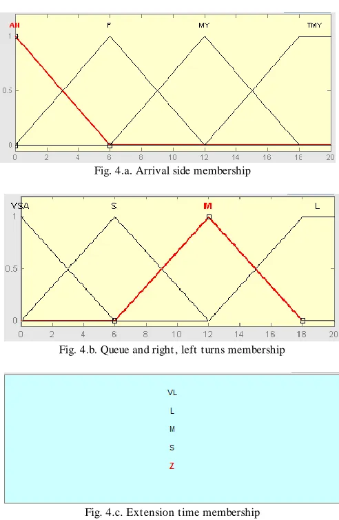
The graphical representation of these variables is presented in Fig. 4.a, 4.b, 4.c; it can be observed that the y-axis is the degree of the membership of each of the fuzzy variable. For the input fuzzy variables the universe of discourse (the x-axis) is the quantized sensor signals which sensed the quantity of the cars. Each input and output have their own linguistic variables , Arrival {Almost, Few, Many, Too Many}, Queue and Right, Left turns {Very Small, Small, Meduim, Long}, Extension Time {Zero, Short, Meduim, Long, Very Long}.The configuration of these membership functions is done according to expert observation of the system and environment. Also the width and center of the membership functions of these fuzzy subsets
can be easily changed and configured according to different traffic
environment and conditions. For example if the junction is too congested, the number of cars in the fuzzy subset "Too Many" or "Very Large" is needed to be increased.
Fig. 4.a. Arrival side membership
Fig. 4.b. Queue and right , left turns membership
Fig. 4.c. Extension time membership
Fig. 5. T he whole design structure
6. FUZZY CONTROL RULES
The fuzzy Set Theory defines fuzzy operator on Fuzzy Sets in terms of simple if-then rules. The controller should be described by using 4^3 = 64 possible combination of AND rules since we have three input variables that each has four linguistic values and. Fuzzy rules work like humans intelligence to decide the optimal choice for the problem which try to solve it . For example in this situation fuzzy rules work as police man which he is use his expert opinion in controlling the traffic in the following way :
If traffic from north of the city is HEAVY AND traffic from the west of the city is LESS AND THEN allow traffic follow from
the north LONGER
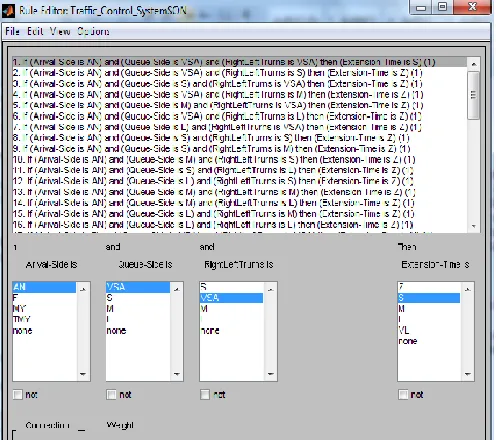
In the development of the fuzzy logic con troller, we use almost similar rules and some examples as shown in fig.6. These rules designed by rule editor also found in Matlab toolbox and can be changed until reaching to the best solution for the problem. Also the basic operation options found in the editor (AND, OR, NOT). By using these options during making the rules we have the whole control to play with estimated result. This is an important point since different traffic have different structures and then the rules that set for one of them may be can‟t using for the other.
Fig. 6. Rules that used to decide the length of extension time
AS: represent the arrival side quantity based on its membership.
QS: represent the queue side quantity based on its membership.
RLT: represent right, left turns in the arrival side quantity based on its membership.
Ex: represent the extension time result that given to the arrival side based on its membership.
The values that assigned to each of these variables obtained from its membership.
7. DESCRIPTION OF BASIC FUZZY CONTROL ALGORITHM S
In the field of fuzzy modeling and control , there are mainly two types of fuzzy rules namely, Mamadani fuzzy rules and Tagaki-Sugeno-Kang(TSK) fuzzy rules. Now we are going to give an example for these two methods.
Mamdani Controller :
Mamdani controller using Min, Max operator on fuzzy rules to make a decision. The fuzzy implication “if- then” is also a fuzzy phrase R defined on AS x QS x RLT x W x Ex with grades of membership function.
µR(AS,QS,RLT ,Ex) = min {
µ
an(x)µ
m(y)µ
m(z)µ
z(n)}Finally two or more fuzzy implications R, S, connected
By "else" form a fuzzy clause C defined on AS x QS x RLT x Ex with grades of membership function
Takagi-Sugeno-Kang Controller:
Tagaki-Sugeno-Kang(TSK) fuzzy rule systems are receiving more and more attention in the recent years. The main differece between TSK models and Mamdani models lies in the consequent part of TSK fuzzy rules is a real-valued function of the input variables instead of a fuzzy set. Due to this feature, TSK fuzzy rule systems have the following merits over the Mamdani fuzzy rule systems:
TSK rule systems are more suitable for various kind of learning algorithms.
TSK rule systems have stronger representative power and therefore are capable of dealing with complex systems.
TSK fuzzy rules can be expressed in the form :
R : if x(1) is A(1) , and …, x(n) is A(n) , then Y= f(x1,x2,….,xn)
Where f() is a real function.
Advantages of the Sugeno Method
It is computationally efficient. It works well with linear techniques (e.g., PID control).
It works well with optimization and adaptive techniques. It has guaranteed continuity of the output surface.
It is well suited to mathematical analysis.
Advantages of the Mamdani Method
It is intuitive
It has widespread acceptance.
It is well suited to human input.
8. SIM ULATION RESULT AND DISCUSSION After the controller was carefully designed, we test the system and discuss the impact of the input variables on the output. In the first level of the simulation we show the effect of the three inputs to resulted extension time. These results obtained from using Tagaki-Sugeno method which represents the optimal case for computing. Also the clearan ce difference between the Tagaki-Sugeno and the other methods of fuzzy‟s methods is the slow growing in the time that will added to the cycle which make the traffic situation more stable.
The simulation implemented in three stages. In each stage we test one of the inputs with other input and discuss their effect on the output.
1 – Density of the arrival side with the density of the queue side vs. external time .
Fig. 7. “ Arrival side” and “ Queue side” vs. External time
As shown in Figure 7, the external time (z-axis) is small when the density of arrival side (y-axis) is small and the density of the queue side (x-axis) also small. Unlike the Mamdani method, here the external time grows slowly its being large only when the arrival side density is very close to large values and the queue side density is very close small value. This is the important different point between the two methods.
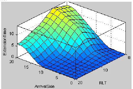
2- Density of the arrival side with the density of the right, left turns.
Fig. 8.“ Arrival side” and “ Right Left turns” vs. External time
3 – Density of the queue side with the density of the right, left turns vs. external time.
Fig. 9. “ Queue side” and “ Right , Left turns” vs. External time
As evident from Figure 9, the external time is close to zero when both the queue side density and the right, left turns are between medium to long values. Then the external time grow slowly and have a long value when both the queue side and the right, left turns are very small. Also in this case we observe that the Sugeno method will reduce the time as much as possible.
TABLE I
THE RESULT OBTAINED FROM TESTING 10 CASE BY USING TAKAGI -SUGENO-KANG METHOD
Number of Cars in the Arrival
S ide
Number of Cars in the Queue
S ide
Right, Left Turns
External Time
10 10 10 2.22
20 10 10 9.33
20 20 10 6
20 5 10 12.3
5 5 10 0.278
5 8 10 0
5 8 20 0
20 10 5 12.3
20 10 15 7
5 12 15 0
Table I shows the result for ten traffic conditions and the result for their extension time obtained by using Takagi-Sugeno method. The Test applying to the different traffic states by first using the Tagaki-Sugeno method defuzzified by Wighted Average method then by comparing our result with Mamdani method[11] results shows in Table II with different defuzzification algorithms.
The test shows that the Sugeno model produce values less than the values that obtained by Mamadani with only Centroid
and Bisector defuzzification methods. But when we use Mean of Maximum or Longest of Maximum methods for defuzzification the result become less than the obtained from Sugeno but with unstable results which doesn‟t reflect the real life condition.
TABLE II
RESULT OF MAMDANI WITH DIFFERENT DEFUZZIFICATION METHODS FOR THE SAME CASES IN TABLE 1
Centroid Method
Bisector Method
Mean of Maximum
Method
Longest of Maximum Method
4.57 3.9 0.9 1.8
8.18 7.5 6 7.8
6 6 6 7.8
13.3 12.9 12 13.8
3.79 2.7 0.9 1.8
2.08 1.8 0.9 1.8
2.08 1.8 0.9 1.8
13.3 12.9 12 13.8
8.46 8.1 6 9
2.25 2.1 1.5 3
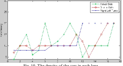
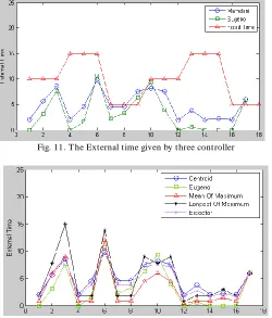
The performance of the fuzzy logic controller can be evaluated by comparing it with the fixed-time controller. This can be done by using the Controller facility where both the controllers are to be simulated. In order to make comparisons between the fuzzy logic algorithms and fixed-time controllers, identical conditions have to be set during the simulation. Fig. 10 shows the traffic flow density that taken to test the performance of each of the controller.
Fig. 10. T he density of the cars in each lane
that the result of Sugeno is less than the other methods of Mamadani. Although the result that produced from Mean of Maximum defuzzification method are very close to Sugeno‟s result. Using fuzzy Sugeno controller provides less waiting time than the other methods without making unstable conditions in the traffic flow.
Fig. 11. T he External time given by three controller
Fig. 12. Comparisons of different Defuzzification method used by Mamadani
Table III shows the improvement percent of Sugeno method with Mamdani method defuzzified by just two methods which are Centroid and Bisector because the other defuzzification method gives us results far from these results which can make unstable change in the extension time of our traffic.
TABLE III
EXP ERIMENT RESULTS UNDER DIFFERENT TRAFFIC CONDITION
Average Waiting Time (s)
1 2 3
Sugeno-WA 7 2.22 12.3
Mamdani-Centroid
8.46 4.57 13.3
Improvement % 17.2 % 51.4 % 7.5
Average Waiting Time (s)
1 2 3
Sugeno-WA 7 2.22 12.3
Mamdani-Biscetor
8.1 3.9 12.9
Improvement % 13.5 % 43 % 4.6
9. CONCLUSION
The fuzzy logic traffic lights controller performed better than the fixed-time controller or even vehicle actuated controllers due to its flexibility. The flexibility here involves the number of vehicles sensed at the incoming junction and the extension of the green time. In the fixed-time controller, being an open-loop system, the green time is not extended whatever the density of cars at the junction. For vehicle actuated traffic light controllers, which is an enhanced version of fixed -time controller, the green time is extended whenever there is a presence of a vehicle. However, these times are fixed in advance up to a maximum time limit. For example when a car is detected, the green time is extended for another 5 or 10 seconds until the maximum time limit is reached. In the fuzzy logic controller, the extension time is not a fixed value. They are all fuzzy variables such as long, medium and small. The number of cars sensed at the input of the fuzzy controllers are also converted into fuzzy values, such as very small, small, medium, too many, etc. In addition to the fuzzy variables as mentioned, the fuzzy controller also has an advantage of performing according to linguistic rules in the manner of how a human would use. The reasoning method in the fuzzy controller is also similar to that of the policeman handling the traffic flow at a typical junction. A simulation experiment was carried out to compare the performance of the fuzzy logic controller with a fixed-time conventional controller. The flow density of the simulation is varied according to real life traffic conditions. It can be observed from the results that the fuzzy logic control system provides better performance in terms of total waiting time as well as total moving time. Less waiting time will not only reduce the fuel consumption but also reduce air and noise pollution. Also this model can be developed in the future to make it more useable. For instance, cooperative traffic network can be treated by this way with respect to the factors that will affect this type of traffic control system, or using fuzzy controller for deciding the most urgent phase that should be open, etc.
References
[1] C. P. Pappis and E. H. Mamdani, “ A Fuzzy Logic Controller For a T raffic Junction”, IEEE T rans. On Systems, Man and Cybernetics, Vol. SMC-7, No. 10, Oct. 1977, pp. 707-717. [2] A Fuzzy Logic Control Simulator for Adaptive T raffic
Management, Jongwan Kim , Division of Comput er and Information Engineering, T aegu University, 1995.
[3] J. Favilla, A. Machion and F. Gomide, “ Fuzzy T raffic Control: Adaptive Strategy”, Proc. 2nd IEEE Int. Conf. on Fuzzy Systems, San Francisco, CA, March 1993, pp. 1371 -1376. [4] Ebrahim Bagheri “ A Novel Fuzzy Control Model Of T raffic
Light T iming At An Urban Intersection”, , Department of Computer Science, University of New Brunswick, Fredericton, Canada . 8 march 2007.
Semarak, Malaysian Journal of Computer Science, Vol. 9 No. 2, December 1996, pp. 29-35
[6] “ Introduction to Fuzzy Logic using MAT LAB”, S. N. Sivanandam, S. Sumathi and S. N. DeepaS. Springer, 2007. [7] M. Nakatsuyama, H. Nagahashi and N. Nishizara, “ Fuzzy
Logic Controller For a T raffic Junction in T he One-Way Arterial Road”, 9th IFAC- World Congress, Budapest, Hungary, 1984, Preprints pp.
[8] “ MAT LAB , Fuzzy Logic T oolbox” J. – S. Ranger Jang , Ned Gulley April 1997.
[9] “ Fuzzy Logic – Foundation(in turkish)” Nazife Baykal , T imur Beyan.2004 Ankara.
[10]R. L. Kelsey and K. R. Bisset, “A Simulation Environment For Fuzzy Control of T raffic Systems”, 12th IFAC- World Congress, Sydney Austria, 18-23 July 1993, Preprints pp. Vol. 5, pp. 553-556.
[11]I.N.Askerzade, Mustafa S.Mahmood , “ Design and Implementation of Intelligent T raffic Control by Using Fuzzy Logic”, T alk in 1st INT ERNAT IONAL FUZZY SYST EMS SYMPOSIUM October 1-2,Ankara, 2009, pp.52-59. [12]„T raffic System Analysis For Engineers And Planners‟,
Martin Wohl, Brian V.Martin, McGraw-Hill, 1967.
[13]Hong Wei Wang Yong , Mu Xuanqin Wu Yan , “ A cooperative fuzzy control method for traffic Lights”, USA - August 25-29, 2001.
[14]S. Chiu and S. Chand, “Self-organizing traffic control via fuzzy logic,” in Proc. 32nd IEEE Conf. Decision Control, 1993, pp. 1987–1902.
[15]Jee-Hyong Lee and Hyung Lee-Kwang, “ Distributed and Cooperative Fuzzy Controllers for T raffic Intersections Group”, IEEE T RANSACT IONS ON SYST EMS, MAN, AND CYBERNET ICS, VOL. 29, NO. 2, MAY 1999
Mr. İman Askerzade received the BS and MS degrees in T heory of Oscillation department (Electronic section) from Physical Faculty of Moscow State University in 1985. He received the Ph.D. (1995) and Dr. Sc. (2004) degree in condensed matter physics from the Institute of Physics of the Azerbaijan National Academy of Sciences. He is an associate professor in the Department of Computer Engineering, University of Ankara, T urkey and leading scientific researcher in Institute of Physics of the Azerbaijan National Academy of Sciences. He is associate member of Abdus Salam International Center for T heoretical Physics (T rieste, Italy). His current research interests include computational condensed matter physics,
fuzzy logic and quantum computing.