IJSRR, 7(4) Oct. – Dec., 2018 Page 2267
Research article Available online www.ijsrr.org
ISSN: 2279–0543
International Journal of Scientific Research and Reviews
Vision based indoor navigation of a Micro Aerial Vehicle using a
Planar Pattern
G. Anitha, B. Anbarasu
*and R. Pradeepa
Department of Aerospace Engineering, Madras Institute of Technology Campus, Anna University, Chennai-600 044, India *E-mail:[email protected]
ABSTRACT
Indoor navigation of micro aerial vehicle (MAV) is still a challenging task due to blocked GPS signal in cluttered indoor environment. GPS signals are not available in indoor environment for autonomous navigation of MAV. Several vision-based navigation algorithms have been developed by researchers in the last few decades for navigation of MAV in indoor environment. This paper describes a vision based pose estimation algorithm for a MAV using a planar pattern. Forward looking raspberry pi 3 camera is mounted on the MAV to acquire image frames of the Planar pattern (landmark). The raspberry pi 3 Camera is calibrated to obtain the intrinsic and extrinsic parameters. Using the image corner points extracted from the planar pattern, world coordinates and the intrinsic parameters the position of the camera is estimated. Using the position of the camera the position of the MAV is estimated.
KEYWORDS:
Micro Aerial Vehicle, Pose estimation, Planar pattern, Raspberry pi, Indoor navigation---
*Corresponding author
B. Anbarasu
Teaching Fellow, Division of Avionics,
Department of Aerospace Engineering
MIT Campus, Anna University, Chennai- 600044 TamilNadu, India.
IJSRR, 7(4) Oct. – Dec., 2018 Page 2268
1. INTRODUCTION
Micro Air vehicle remotely piloted or having an autopilot are generally defined as unmanned air vehicles (UAV). Unmanned air vehicle (UAVs) can be used both for civilian and military applications. They could have different missions according to their civil or military usage such as ground surveillance, payload or cargo carries traffic control, and geological surveying application. Unmanned air vehicle, UAVs may considered as the future of aviation. Technology advances in aviation electronics, avionics, seem to enable the air vehicles to fly themselves with small help of human pilot. Nowadays, all over the world, a lot of UAV concepts have emerged and most of them have been made operational successfully.
A micro aerial vehicle (MAV) is a class of miniature UAVs that has a size restriction and may be autonomous. Modern craft can be as small as 5 centimeters. Projected concentric circles are used to calibrate the camera1. Vision based pose estimation algorithm and control laws are developed for navigation of mobile robot2. Camera calibration method is proposed based on planar pattern by using the motion information of the camera or planar pattern3. Three mutually orthogonal vanishing points are used to obtain the intrinsic parameters of the camera4. Pose of the camera can be extracted from the detected points and lines in the image frames5. Line correspondences (2D to 3D) are used to determine the location of the camera6. Optical flow is used to estimate the lateral position, velocity of the quadrotor7. Micro Aerial Vehicle (MAV) pose is estimated based on vision based SLAM (simultaneous localization and mapping) algorithm8. Position of the UAV is estimated at each waypoint from the features extracted from the landmarks9.
IJSRR, 7(4) Oct. – Dec., 2018 Page 2269
2.
HARDWARE SETUP AND CONFIGURATION
2.1. Raspberry Pi 3 - Model B
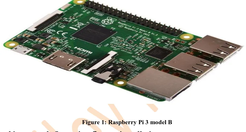
Raspberry Pi 3 - Model B single board computer consists of Broadcom BCM2387 chipset, .2GHz Quad-Core ARM Cortex-A53, 802.11 b/g/n Wireless LAN and Bluetooth 4.1 (Bluetooth Classic and LE), 1GB RAM, 64 Bit CPU, 4 x USB ports, 4 pole Stereo output and Composite video port, Full size HDMI, 10/100 BaseT Ethernet socket, CSI camera port for connecting the Raspberry Pi camera, DSI display port for connecting the Raspberry Pi touch screen display, Micro SD port for loading your operating system and storing data and Micro USB power source. Raspberry Pi 3 model B is shown in Figure 1.
Figure 1: Raspberry Pi 3 model B
2.2. Raspbian stretch Operating System installation
To develop vision based obstacle detection algorithm, Linux based operating system (OS) called Raspbian stretch with desktop image and Python Open CV package was installed on the micro SD card and Raspberry Pi 3 model B single board computer was booted from the memory card. Raspberry Pi 3 Camera is connected through 15 pin ribbon cable to the MIPI Camera Serial Interface (15-pin) on the Raspberry Pi 3 model B board. After installing Raspbian Stretch with desktop image, Raspberry Pi 3 model B can be used as a Standalone desktop by connecting monitor, keyboard and mouse to the supplied ports on the Pi. Raspbian stretch OS was updated along with its firmware by connecting Pi to the internet via ethernet.
2.3. Open cv installation
IJSRR, 7(4) Oct. – Dec., 2018 Page 2270
from GitHub then by using CMake python dependency of the Open CV packages are built and installed through terminal on Raspberry Pi.
2.4. Raspberry Pi Camera board
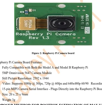
Open CV is a computer vision library.In this work. The Raspberry Pi Camera Board (Figure 2) plugs directly into the CSI connector on the Raspberry Pi. The Raspberry Pi Camera Module v1 is a 5-megapixel Omni Vision OV5647 camera. Raspberry Pi Camera can be accessed with Pi camera Python library.
Figure 2: Raspberry Pi Camera board
The Raspberry Pi Camera Board Features:
Fully Compatible with Both the Model A and Model B Raspberry Pi 5MP Omnivision 5647 Camera Module
Still Picture Resolution: 2592 x 1944
Video: Supports 1080p @ 30fps, 720p @ 60fps and 640x480p 60/90 Recording 15-pin MIPI Camera Serial Interface - Plugs Directly into the Raspberry Pi Board Size: 20 x 25 x 9mm
Weight 3g
3. PROPOSED METHOD FOR POSITION ESTIMATION OF MAV USING A
PLANAR PATTERN
3.1. Camera calibration parameter
IJSRR, 7(4) Oct. – Dec., 2018 Page 2271
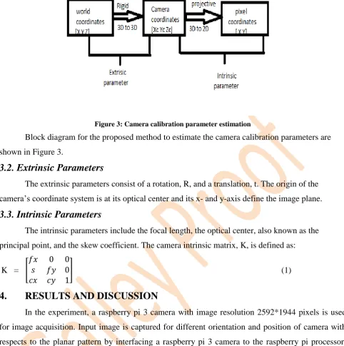
Figure 3: Camera calibration parameter estimation
Block diagram for the proposed method to estimate the camera calibration parameters are shown in Figure 3.
3.2. Extrinsic Parameters
The extrinsic parameters consist of a rotation, R, and a translation, t. The origin of the camera’s coordinate system is at its optical center and its x- and y-axis define the image plane.
3.3. Intrinsic Parameters
The intrinsic parameters include the focal length, the optical center, also known as the principal point, and the skew coefficient. The camera intrinsic matrix, K, is defined as:
K = [
] (1)
4.
RESULTS AND DISCUSSION
In the experiment, a raspberry pi 3 camera with image resolution 2592*1944 pixels is used for image acquisition. Input image is captured for different orientation and position of camera with respects to the planar pattern by interfacing a raspberry pi 3 camera to the raspberry pi processor. Input image frame with planar pattern is shown in Figure 4.
IJSRR, 7(4) Oct. – Dec., 2018 Page 2272
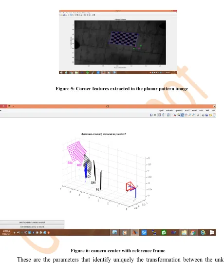
Figure 5 shows the extracted corner features in the camera calibration process to obtain the intrinsic and extrinsic parameters.
Figure 5: Corner features extracted in the planar pattern image
Figure 6: camera center with reference frame
These are the parameters that identify uniquely the transformation between the unknown camera reference frame and the known world reference frame. Figure 6. shows the extrinsic parameter (camera center) with reference frame. Relative position of the grid with respect to the camera. In this frame, (Ox, Xc, Yc, Zc) is the camera reference frame. Red pyramid corresponds to the effective field of view of the camera defined by image plane. Calculated intrinsic parameter values for Raspberry pi 3 camera are given below.
IJSRR, 7(4) Oct. – Dec., 2018 Page 2273
Principal point:
cc = [ 296.183240765960190; -59.777093936524651]; Skew coefficient = 0.000000000000000;
camera intrinsic parameter values are computed as follows:
k=[
]
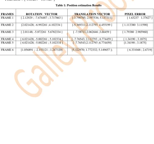
Calculated extrinsic parameter values for different position and orientation of Raspberry pi 3 camera mounted on the MAV.The position estimation results of MAV such as translation and rotation vector are reported in Table 1.
Rotation vector = [ 2.12929 ; -7.676487 ; 3.717863 ] Translation vector = [ -3.790785 ; 2.597536 ; 5.137311] Pixel error = [ 1.63237 1.37627 ]
Table 1: Position estimation Results
FRAMES ROTATION VECTOR TRANSLATION VECTOR PIXEL ERROR
IJSRR, 7(4) Oct. – Dec., 2018 Page 2274
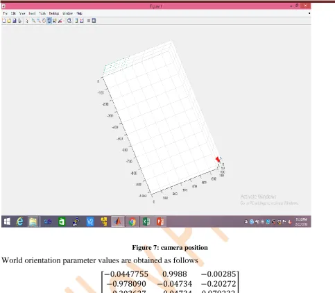
Figure 7: camera position
World orientation parameter values are obtained as follows
[ ]
Figure 7 shows the position of the camera with respect to the planar pattern in the sequence of image frames.
5. CONCLUSION
Vision based navigation algorithm for a MAV using a planar pattern is developed. The intrinsic and extrinsic parameters of the raspberry pi 3 camera was estimated to compute the position of Micro Aerial Vehicle in indoor environment. The position of the MAV is estimated based on the developed vision based algorithm using a sequence of image frames acquired from the raspberry pi 3 camera. Experimental results show that the proposed algorithm is suitable for estimation of position and orientation of camera and MAV in real time.
REFERENCES
IJSRR, 7(4) Oct. – Dec., 2018 Page 2275
2. Ma Y, Kosecka J, Sastry S. Vision guided navigation for a nonholonomic mobile robot. IEEE Transactions on Robotics and Automation. 1999; 15(3): 521- 536.
3. hang . exi e new technique for camera ca i ration. IEEE Trans. Pattern Anal. Mach. Intell. 2000; 22(11): 1330–1334.
4. WangG, TsuiHT, HuZ, Wu, F. Camera calibration and 3d reconstruction from a single view based onscene constraints. Image Vis Comput.2005; 23(3):311–323.
5. Ansar A,Daniilidis K. Linear pose estimation from points or lines. IEEE Trans. Pattern Anal. Mach. Intell.2003; 25(5): 578–589.
6. Liu Y, Huang TS, Faugeras OD. Determination of camera location from 2-d to 3-d line and point correspondences. IEEE Trans. Pattern Anal. Mach. Intell. 1990; 12(1): 28–37.
7. Carrillo LRG, Fantoni I, Rondon E. Three-dimensional position and velocity regulation of a quad-rotorcraft using optica f ow IEEE Trans. Aerosp. Electron. Syst. 2015; 51(1): 358-371. 8. Heng L, Lee GH, Pollefeys M. Self-calibration and visual SLAM with a multi- camera
system on a micro aerial vehicle. Autonomous Robots. 2015; 39:259–277.
9. Dawadee A, Chahi,Nandagopal D. An Algorithm for Autonomous Aerial Navigation Using Landmarks. J. Aerospace Eng.2016; 29(3):1-27.