ISSN(Online): 2319-8753 ISSN (Print): 2347-6710
I
nternational
J
ournal of
I
nnovative
R
esearch in
S
cience,
E
ngineering and
T
echnology
(A High Impact Factor & UGC Approved Journal)
Website: www.ijirset.com
Vol. 6, Issue 9, September 2017
Modelling and Simulation of A SPV-DG-BESS
Hybrid Micro Grid System by Using Fuzzy
Logic Controller
M.Divya1, P.Parvathee Devi 2
PG Student, Dept. of Electrical & Electronics Engineering, Sri Padmavati Mahila Visvavidyalayam, Tirupati,
A.P. India1
Assistant Professor, Dept. of Electrical & Electronics Engineering, Sri Padmavati Mahila Visvavidyalayam, Tirupati,
A.P. India2
ABSTRACT: The proposed system manages the discontinuous way of the energy created by the PV array and it likewise gives control quality change. The PV array is incorporated through a DC-DC help converter and controlled utilizing a most extreme power point following (MPPT) calculation to get the greatest power under shifting working conditions. The battery energystorage system (BESS) is incorporated to the diesel motor generator (DG) set for the planned load administration and power current inside the system. The induction based control calculation is utilized for load adjusting, harmonic end and reactive power remuneration under three phase four-wire straight and nonlinear loads. A four-leg voltage source converter (VSC) with BESS additionally gives nonpartisan current payby using fuzzy logic controller
KEYWORDS: Admittance based control algorithm, BESS, DG set, Four-leg VSC, Neutral current compensation, Power quality, Solar photovoltaic array, Standalone system
I. INTRODUCTION
ISSN(Online): 2319-8753 ISSN (Print): 2347-6710
I
nternational
J
ournal of
I
nnovative
R
esearch in
S
cience,
E
ngineering and
T
echnology
(A High Impact Factor & UGC Approved Journal)
Website: www.ijirset.com
Vol. 6, Issue 9, September 2017
power supply. Keeping in mind the end goal to keep up the productivity and to diminish the upkeep cost, the DG set is made to work at 80-100% of its full limit .This is on the grounds that, under light load conditions, the productivity lessens and the upkeep cost likewise increments as the DG set is subjected to carbon develop. For the most part to maintain a strategic distance from these issues, the DG is worked by keeping a base loading of 80% by method for battery charging or the DG is made to turn on/off contingent on the loading. Notwithstanding, the turn on/off of the DG set is normally not prescribed.
1. The load may differ regularly. In this manner, the rehashed turn on/off of DG builds the mechanical support. 2. The battery life diminishes as the releasing current is high amid transient periods. Other than the PMSG driven by diesel motor does not require a different excitation control. The machine is hearty, proficient, brushless development and with less support. A BESS is fused to give load leveling if there should arise an occurrence of varieties in PV arrayoutput control. The BESS is considered as perfect energystorage for an independent system when contrasted with packed air, super capacitors, flywheels, pumped hydro, and superconducting attractive capacity. The usage of an independent system concocted of PV array, DG set and BESS plans to satisfy the accompanying prerequisites:
1. To control the purpose of regular coupling (PCC) voltage relying on the sunlight based irradiance varieties, load changes and unbalances.
2. There is no prerequisite for the estimation of load for turn on/off of DG.
3. The power nature of the system is enhanced by lessening the total consonant twisting (THD) of PCC voltages and DG set currents under IEEE-519 standard.
4. To adequately direct power current amongst source and load.
5. The VSC (Voltage Source Converter) of BESS gives reactive power pay and keeps up the adjusted DG currents. This decreases the vibration of shaft and overheating of machines.
6. It permits nonpartisan current remuneration utilizing four leg VSC.
These days, the quick increment in the utilization of nonlinear loadsfor example, PCs, hardware apparatuses, restorative gear, iceboxes and so on has accentuated the sympathy toward power quality in the electrical dispersion system. These loads infuse harmonic and bend the current and voltage waveforms bringing on poor power quality issues. The conceivable series for the alleviation of the power quality issues is with consideration of custom power gadgets (CPDs) while meeting the IEEE-519 standard. Three-phase four-wire loads are likewise known to experience the ill effects of the issue of nonpartisan current because of non-linearity and unbalance introduce in the system. This may deliver extensive measure of impartial current which comprises of triplen harmonic. The nonpartisan current may bring about over-loading of the appropriation system and causes extra warmth misfortunes which might be perilous and represents a real danger to the connected gear. A four-leg VSC is utilized for nonpartisan current pay notwithstanding moderate the present harmonic with other detailed points of interest. Furthermore, the adaptable operation of the system relies on execution of the different control techniques. A portion of the control calculations that have been connected for controlling are multi circle methodology , sliding mode control ,P controller based system ,FLC based control strategy and improved phase bolted procedure .The creators have neglected to examine the power quality and reactive power pay. The reaction of these controllers to the unbalance and element conditions is moderate.
In this paper, a permission based control calculation is connected for the assessment of reference power segment of source currents in PV-DG cross breed system. The permission of the load is assessed utilizing the dynamic and reactivepowers of the load. The conductance (GL) and susceptance (BL) are removed from the evaluated dynamic power and reactivepower of the three-phase four-wire loads separately. It is a straightforward scientific detailing in view of sinusoidal Fryze current control. This control methodology depends on the Lagrange‟s multiplier technique
and the crucial standard of the PQ hypothesis where the calculation through the Clarke‟s change is dispensed with.
Thusly it gives a change in the numerical counts. Here, the sources of info are the loadcurrents (iLa, iLb, iLc) and load
voltages (va, vb, vc) which are further utilized for the estimation of the dynamic (p) and reactive (q) control segments
utilizing the equation specified in this paper. The wavering part of power is dispensed with as it is gone through the low pass filter to acquire Pdc and Qdc. These are utilized for the estimation of the reference conductance and susceptance,
ISSN(Online): 2319-8753 ISSN (Print): 2347-6710
I
nternational
J
ournal of
I
nnovative
R
esearch in
S
cience,
E
ngineering and
T
echnology
(A High Impact Factor & UGC Approved Journal)
Website: www.ijirset.com
Vol. 6, Issue 9, September 2017
acknowledged utilizing a four-leg VSC with permission control calculation. The execution is checked exploratory review utilizing Digital Signal Processor (DSP-dSPACE) under both direct and nonlinear loads.
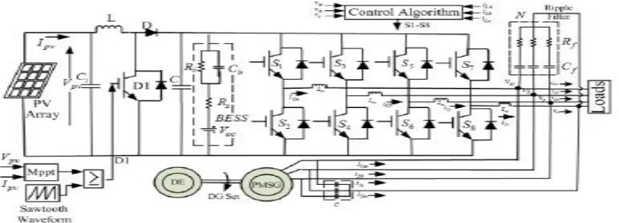
Fig:1 Proposed PV-diesel hybrid system
II. SYSTEM DESIGN AND CONFIGURATION
The standalone system comprises of a PV array alongside a lift converter, MPPT controller, and diesel motor driven lasting magnet synchronous generator (PMSG), a four-leg VSC with BESS and three-phase four-wire AC loads as appeared in Fig. 1. The voltage at the purpose of regular coupling is reestablished by planning the reactive power through VSC control. Under fluctuating states of era and loads, BESS offers charging amid the daytime when the insolation is vast and the load is less. The battery releases to adjust for any shortfalls. The DG set works while keeping up the systemfrequency under fluctuating generation and loads. The terminal capacitor gives a consistent evaluated terminal voltage at no load. A four leg VSC is interfaced alongside its DC bus. The swell filter and interfacing inductors are utilized to dispense with the switchingharmonic. The contemplations required for the determination of different components are examined as takes after and their qualities are given in Appendix.
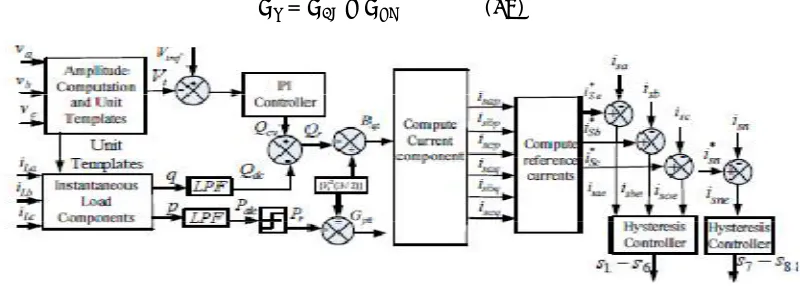
Fig. 2 Schematic diagram of the proposed system
A. Solar Photovoltaic Array
ISSN(Online): 2319-8753 ISSN (Print): 2347-6710
I
nternational
J
ournal of
I
nnovative
R
esearch in
S
cience,
E
ngineering and
T
echnology
(A High Impact Factor & UGC Approved Journal)
Website: www.ijirset.com
Vol. 6, Issue 9, September 2017
more, current at the most extreme power of the solar. This IC technique performs great with clamor dismissal and less perplexity because of system progression. The IC technique has been utilized here which displays the maximum power point contingent on the slant of the power bend. The slant of the bend is zero at maximum power point. The MPPT controller directs the control flag of the DC–DC help converter until the taking after condition is fulfilled.
/ =−( / ) ( )
B. Boost Converter
The design parameters for a lift converter rely on the current ripple, voltage ripple and power rating. The lift converter is interfaced with MPPT controller for following the maximum power.
It is utilized to help the voltage to 400 V to sustain energy to the battery. The inductor of the lift converter is given as,
=
∆ =
∗ . ∗ ∗ ^
. ∗ . = . ≈ ( )
Where Vin is the info voltage. D is the obligation cycle, T is the day and age and ΔI is the inductor swell current. The estimation of ΔI is taken as 10% of the info current. The variety brought on by the swells on the PV power is taken care
with the expansion of a capacitor (Ci) at the contribution of the lift converter as appeared in Fig.1. This retains the swells and smoothen the power current inside the system.
C. Battery Energy Storage System
The battery is connected at the DC connection of the VSC. The battery is aenergystorage unit, its energy is spoken to in kilowatt-hour (kWh), a capacitor is utilized to demonstrate the battery unit as appeared in Fig 1. A 2.8kWh limit battery rack is utilized for the energystorage. In this manner, 36 areas of 12 V, 7Ah are connected in series. The parallel design of Rb and Cb depicts the charging/releasing put away energy and voltage.
The estimation of resistance Rb= 10kω is substantial while Rs= 0.1ω is little for all commonsense purposes. The battery works as per the load varieties. In conditions, when the load request has expanded, under those conditions the power put away in the battery is utilized and along these lines the battery begins releasing as per its release rate. If there should be an occurrence of diminished load request, the battery charges from the available PV control once the load request is fulfilled.
D. Ripple Filter
The principal arrange low-pass filter is tuned at a large portion of the switchingfrequency. It is utilized to filter the switching swells of a VSC at PCC. They chose switchingfrequency is 10 kHz. The switchingfrequency of 10 kHz is chosen as it would give lessened misfortunes and the span of the segments is suitable as indicated by the chose switchingfrequency when contrasted with other benefit of switchingfrequency. The estimation of capacitor is taken as
10μF. The swell filter comprises of a resistor in series with the capacitor. The estimation of the resistor is thought to be
5Ω.These chosen parameters of the system are given in Appendix.
III. CONTROL ALGORITHM
The control calculation separates the principal segment of the loads utilizing permission control system. Further, dynamic and reactive power segments of the loadcurrents are resolved. The PI (Proportional Integral) control circle produces reactive power (Qcv) for voltage control with a specific end goal to adjust for any progressions in
reactive power in support to vacillations in PCC voltages. The reference susceptance (Bqt) for reactive segment of
source current is registered by deducting the three phaseloadreactive power (Qdc) from the PI controller output (Qcv).
The reference conductance (Gpt) is assessed utilizing the reference load dynamic power (Pr). The load dynamic power
ISSN(Online): 2319-8753 ISSN (Print): 2347-6710
I
nternational
J
ournal of
I
nnovative
R
esearch in
S
cience,
E
ngineering and
T
echnology
(A High Impact Factor & UGC Approved Journal)
Website: www.ijirset.com
Vol. 6, Issue 9, September 2017
for acquiring the outcomes and the event of error inside the system is additionally decreased. Subsequently, the system execution enhances with this control calculation.
A. Determination of Unit Templates
The amplitude of PCC voltage and phase voltages are employed for the computation of in-phase unit template,
= { ∗( + + ))/ } ( )
= , = , = ( )
The quadrature unit templates are estimated as,
= (− + )/√ ( )
= ( + − )/ √ ( )
= (− + − )/ √ ( )
B. Admittance Control Technique
The instantaneous load dynamic power (p) and load reactive power (q) segments are processed as takes after. The figured quick parts of load power comprise of AC and DC components. The DC segments are removed utilizing LPF (Low Pass Filter).
= { ( + + )} = + ( )
=−{ ( + + )} = + ( )
The voltage error for the kth instant at PCC is given as,
( ) = ( )− ( ) ( )
Where Vtref (k) is the terminal AC reference voltage adequacy and Vt (k) is the amplitude of three phase detected AC
voltages at PCC as given in (10). The PI controller output for keeping up the PCC voltage at the kth testing moment is
given as,
( ) = ( − ) + [ ( )− ( − )] = ( ) ( )
Where kpv and kiv denote the proportional and integral gains of the PI controller. The reference reactive power
component (Qr) is computed from the difference of the PI controller output (Qcv) and the load reactive power
component (Qdc) as,
= − ( )
ISSN(Online): 2319-8753 ISSN (Print): 2347-6710
I
nternational
J
ournal of
I
nnovative
R
esearch in
S
cience,
E
ngineering and
T
echnology
(A High Impact Factor & UGC Approved Journal)
Website: www.ijirset.com
Vol. 6, Issue 9, September 2017
The active power drawn from the DG set (Pr) is limited to 0.8PR≤Pdc≤1.0PR. The reference source active power
component (Pr) is obtained. Where PR is rated power of DG set.
The reference conductance (Gpt) and susceptance (Bqt) of the load corresponding to the reference active (Pr) and
reactive power (Qr) components are derived as,
= /{ ( / )} ( )
= /{ ( / )} ( )
= : = : = ( )
= : = : = ( )
The total reference source currents (iSa*, iSb*, iSc*) are obtained as sum of in phase and quadrature components of
reference source currents of individual phases as,
∗ = + ; ∗ = + ; ∗ = + ( )
C. Neutral Current Compensation
This fourth leg of VSC gives coordinate control over the source unbiased current. The reference impartial current (iSn*) is contrasted and the detected source unbiased current (iSn) as appeared in Fig. 3.These are utilized as a
part of hysteresis current controller to create switching signals for 4-leg of VSC.
Simulation results
Performance of proposed system under unbalance nonlinear load
vs
Is
ISSN(Online): 2319-8753 ISSN (Print): 2347-6710
I
nternational
J
ournal of
I
nnovative
R
esearch in
S
cience,
E
ngineering and
T
echnology
(A High Impact Factor & UGC Approved Journal)
Website: www.ijirset.com
Vol. 6, Issue 9, September 2017
iLb
iLc
ica
isn
ISSN(Online): 2319-8753 ISSN (Print): 2347-6710
I
nternational
J
ournal of
I
nnovative
R
esearch in
S
cience,
E
ngineering and
T
echnology
(A High Impact Factor & UGC Approved Journal)
Website: www.ijirset.com
Vol. 6, Issue 9, September 2017
icn
Vt
Extension topic
Fuzzy Logic Controller
Fuzzy logic is a complex mathematical method that allows solving difficult simulated problems with many inputs and output variables. Fuzzy logic is able to give results in the form of recommendation for a specific interval of output state, so it is essential that this mathematical method is strictly distinguished from the more familiar logics, such as Boolean algebra.
Fuzzy logic allows to lower complexity by allowing the use of imperfect information in sensible way. It can be implemented in hardware, software, or a combination of both. In other words, fuzzy logic approach to problems’ control mimics how a person would make decisions, only much faster.
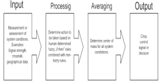
The fuzzy logic analysis and control methods shown in Figure 1 can be described as:
1. Receiving one or large number of measurements or other assessment of conditions existing in some system that will be analyzed or controlled.
2. Processing all received inputs according to human based, fuzzy ”if-then” rules, which can be expressed in simple language words, and combined with traditional non-fuzzy processing.
ISSN(Online): 2319-8753 ISSN (Print): 2347-6710
I
nternational
J
ournal of
I
nnovative
R
esearch in
S
cience,
E
ngineering and
T
echnology
(A High Impact Factor & UGC Approved Journal)
Website: www.ijirset.com
Vol. 6, Issue 9, September 2017
The following is Fuzzy Logic Control/Analysis Method diagram.
Figure 1. The fuzzy logic Control-Analysis method
In order to operate fuzzy logic needs to be represented by numbers or descriptions. For example, speed can be represented by value 5 m/s or by description “slow”. Term “slow” can have different meaning if used by different persons and must be interpreted with respect to the observed environment. Some values are easy to classify, while others can be difficult to determine because of human understanding of different situations. One can say “slow”, while other can say “not fast” when describing the same speed. These differences can be distinguished with help of so-called fuzzy sets.
Usually fuzzy logic control system is created from four major elements presented on Figure 2: fuzzification interface, fuzzy inference engine, fuzzy rule matrix and defuzzification interface. Each part along with basic fuzzy logic operations will be described in more detail below.
Figure 2. Fuzzy logic controller
Extension results
VS
ISSN(Online): 2319-8753 ISSN (Print): 2347-6710
I
nternational
J
ournal of
I
nnovative
R
esearch in
S
cience,
E
ngineering and
T
echnology
(A High Impact Factor & UGC Approved Journal)
Website: www.ijirset.com
Vol. 6, Issue 9, September 2017
ILa
iLb
iLc
iCa
Isn
ISSN(Online): 2319-8753 ISSN (Print): 2347-6710
I
nternational
J
ournal of
I
nnovative
R
esearch in
S
cience,
E
ngineering and
T
echnology
(A High Impact Factor & UGC Approved Journal)
Website: www.ijirset.com
Vol. 6, Issue 9, September 2017
Icn
Vt
Comparison table of proposed and extension
Voltage source Current source
Proposed 13.21 14.34
Extension 3.60 2.56
IV. CONCLUSION
The admittance-based control technique has been used for a PV-diesel-battery hybrid system with Fuzzy Logic Controller (FLC) for an uninterrupted power supply and power quality improvement. The incremental based MPPT algorithm has delivered maximum solar array power under varying conditions of temperature and insolation radiation. The technique has been demonstrated to eliminate harmonics, load balancing, and to provide neutral current compensation by incorporating four-leg VSC in the system. The PCC voltage and frequency have been maintained constant. Satisfactory performance of the system has been observed through test results obtained for steady-state and dynamic conditions under both linear/nonlinear loads.
REFERENCES
[1] Z. Jiang, “Power Management of Hybrid Photovoltaic-Fuel Cell Power Systems”, Proc. of IEEE Power Engg. Society General Meeting, Montreal Quebec, Canada, 2006.
[2] A. Naik, R.Y. Udaykumar and V. Kole, “Power management of a hybrid PEMFC-PV and Ultra capacitor for stand-alone and grid connected applications”, Proc. of IEEE Int. Conf. Power Electron. Drives and Energy Sys. (PEDES), 2012, pp. 1-5.
[3] J. Philip, C. Jain, , K. Kant, B. Singh, S. Mishra, A. Chandra and K. Al- Haddad “Control and implementation of a standalone solar photo-voltaic hybrid system”, Proc. of IEEE Industry Applications Society Annual Meeting, Addison, TX, 18- 22 Oct. 2015, pp.1-8.
[4] J. Philip, B. Singh and S. Mishra, “Design and operation for a standalone DG-SPV-BES micro grid system”, Proc. of 6thIEEE Power India Int. Conf. (PIICON), Delhi, 5-7 Dec, 2014, pp.1-6.