Analysis of the Performance of the Bidirectional
Three-Level and Five Level DC–DC Converter
KOTA VENKATA PADMA M-tech Scholar
Department of Electrical & Electronics Engineering, Mallareddy Engineering College(Autonomous),
Maissammaguda,Secundrabad 50010; Telangana, India.
Email:[email protected]
CH.NARENDRA KUMAR Assistant Professor
Department of Electrical & Electronics Engineering, Mallareddy Engineering College(Autonomous),
Maissammaguda,Secundrabad 50010; Telangana, India.
Email:[email protected]
Abstract-In this paper Bidirectional Five-Level DC–DC Converter is implemented for automotive applications. Bidirectional dc/dc converter is used in battery/ultra-capacitor electric vehicles. a three-level non-isolated bidirectional dc/dc converter (TLC) as the power electronics interface between the battery and the UC, instead of a conventional two-quadrant buck/ boost converter (CBC), which would increase the conversion efficiency and reduce the size of the magnetic components. In this regard, the Five-level converter was analyzed and comprehensively compared with three level CBC and interleaved bidirectional converter in terms of magnetic component size and efficiency considering a UDDS drive cycle where the battery and UC power are split using three-level converter. Particularly in higher switching frequencies, the efficiency of this converter decreases due to increased switching losses. This paper has proposed using a five-level non-isolated bidirectional dc/dc converter (TLC) as the power electronics interface between the battery and the UC, instead of a conventional three level buck/ boost converter (CBC). The simulation results are presented by using Matlab/Simulink software.
Index Terms—Electric vehicles (EVs), interleaved converter, non-isolated dc–dc converter, three-level converter, Ultra capacitor (UC).
I. INTRODUCTION
Electrochemical double layer capacitors (EDLC), well known as the ultra-capacitors, have received lot of attention in power conversion application. They have been used in controlled industrial electric drives, traction and automotive drives; uninterruptible power supplies (UPS) and active filters. Fig.1 shows simplified block diagram of a controlled electric drive equipped with an ultra-capacitor. The ultra-capacitor is used to store the drive braking energy when the drive is braking. The stored energy is recovered when the drive operates in motoring mode [1]. Moreover, the ultra-capacitor powers the drive when the power supply is not available, for example the mains short interruptions.
Nowadays’ ultra-capacitors are composed of two electrodes separated by a porous membrane, so-called a separator, and impregnated by a solvent electrolyte [2]. The electrodes are made of porous conducting material such as activated carbon. Specific surface area of the electrode is as high as 2000m2/g. Such a large surface area and very thin layer of the charges (in order of nm)
gives specific capacitance up to 250F/g. Rated voltage of the ultra-capacitor cell is determined by the decomposition voltage of the electrolyte [3]. Typical cell voltage is 1 to 2.8V, depending on the electrolyte technology. To obtain higher working voltage that is determined by the application, elementary cells are series connected into one capacitor module. Ultra-capacitors as energy storage devices have found very wide application in power conversion due to their advantages over the conventional capacitors and electro-chemical batteries; high energy and power density, high efficiency, high cycling capability and long life. To achieve the drive system flexibility and high efficiency, a switching mode power converter is used as a link between the ultra-capacitor and the drive dc bus. The converter is controlled in the way depending on the system requirements; control of the dc bus voltage, the ultra-capacitor state of charge, active sharing of the energy between the drive and ultra-capacitor and so on [4-6].
Fig.1.Controlled electric drive system with energy storage device.
and ripple current are quite greater than of that one operates in continuous conduction mode (CCM) [7-8]. This causes problem of the inductor losses, particularly the core losses. Isolated dc-dc converter topologies with soft switching have been analyzed. These topologies are attractive solution when ratio between the dc bus voltage and the ultra-capacitor voltage is high, greater than 2. If the ratio is lower than 2, the efficiency is lower than that of a non-isolated topology. Three-level converters are well adopted solution in applications with high input voltage and high switching frequency. The switches are stressed on half of the total dc bus voltage. This allow us to use lower voltage rated switches having better switching and conduction performance compared to the switches rated on the full blocking voltage.
Power converters synthesizing more than two voltage levels, such as the neutral point clamped (NPC), cascaded H-bridge (CHB) and flying capacitor (FC), are traditionally known as multilevel converters. Usually, the multilevel topology is used in medium or high voltage inverter applications [9]. The CHB topology is typically used with multiple cascaded DABs to achieve higher voltages. In the CHB topology, a DAB module itself does not synthesize multilevel (e.g., 3L, 5L, and so on) voltages, like
NPC or FC. Because of the simple control and modulation scheme along with the simpler circuit structure, the 3L NPC is ahead of others in various industrial applications [10]. Very few works have been published on ML-DAB. A silicon carbide junction gate field-effect transistor (SiC-JFET) based 25-kW, high switching frequency DAB has been proposed in [11], where both primary and secondary bridges produce two-level voltages, although the secondary side bridge is formed in the NPC configuration. A detailed analysis on a semi-dual active bridge (S-DAB) has been presented, where the primary and secondary bridges produce 2L and 3L voltage waveforms, respectively, which are phase-shifted to control the power flow. The concept of symmetric modulation for 2L-to-5L bridge voltages with an NPC-based secondary bridge has been introduced by the authors in [12], which has the advantage of having simple mathematical representation and a minimum number of parameters to define the voltage waveforms and to control the power flow through the ML-DAB. In [13], an NPC-based multilevel DAB is reported with capacitor voltage balancing.
II. DC-DC CONVERTER
Basic dc-dc converters such as buck and boost converters (and their derivatives) do not have bidirectional power flow capability. This limitation is due to the presence of diodes in their structure which prevents reverse current flow. In general, a unidirectional dc-dc converter can be turned into a bidirectional converter by replacing the diodes with a controllable switch in its structure. The
Figure.2.Illustration of bidirectional power flow.
III. BIDIRECTIONAL THREE-LEVEL DC–DC CONVERTER
In a battery/UC-powered drivetrain, where the battery is connected to the high-voltage dc link via a bidirectional converter, the converter is “power controlled” through stepping-up the battery voltage during propulsion and stepping-down the high voltage dc link to the battery voltage during regenerative braking. A majority of the studies in the literature use the conventional two-level buck/boost converter (CBC) due to its simple structure and control [24]–[31]. However, in high-power applications, the boost inductor becomes the major component that increases the volume, weight, and cost of the system. Moreover, high-voltage switches must be used, which, in turn, causes higher losses. By using TLC, significant improvements can be achieved over the CBC.
Fig. 3. Drivetrain of the battery/UC vehicle with a bidirectional converter.
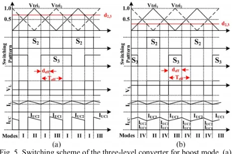
The switching scheme for the TLC converter is given in Fig. 5. The switch turn-on times are phase-shifted, resulting in an effective inductor current ripple frequency that is equal to twice the switching frequency. This effective period is shown as Tseff in Fig. 5. The boost and buck operation modes of the TLC are shown in Figs. 6 and 7, respectively. Since operations of the buck and boost modes are similar, only boost mode is explained. The operation of the circuit can be divided into four modes. Based on the duty cycle value, the sequence of the equivalent circuits is separated into two. The climax value of the duty cycle of the switches, i.e., d, is 0.5. Basically, if d < 0.5, the sequence of equivalent circuits is IV–II– IV–III and keeps repeating. Since the control signals of each switch is displaced by 180◦, as the duty cycle gets
higher than 0.5, the control signals begin to overlap. This overlap causes a new equivalent circuit to emerge. The new equivalent circuit sequence becomes I–II–I–III. The output-voltage-to-input-voltage ratio for continuous conduction mode (CCM) operation can be found through analyzing the inductor current ripple within one cycle of the effective switching period. When d > 0.5, the voltage conversion ratio can be expressed as
(1) Where deff is
(2) Here, dS2 and dS3 denote the duty cycles of switches S2 and S3. It is worth mentioning that the duty cycles of S2 and S3 are the same; hence, the effective duty cycle can be rewritten as
(3) Where d = dS2 = dS3. The output-voltage-to-input-voltage ratio, when d < 0.5, can be found by equalizing mode II or III and mode IV, i.e.,
(4) The effective duty cycle for this mode is the sum of the individual duty cycles
(5)
Fig. 4.Non isolated bidirectional buck/boost converters. (a) Two-level (CBC). (b) Interleaved (BIC). (c) Three-level (TLC).
IV. COMPARISON OF THREE-LEVEL CONVERTER WITH THE STATE-OF-THE-ART
CONVERTERS
the output voltage. In fact, the parasitic capacitance losses are expected to be even lower as low-voltage switches are used. On the passive component side, the diode reverse recovery losses are lower as reverse voltage is only half the output voltage, and low-voltage diodes typically recover faster. This section compares bidirectional buck/boost dc–dc converter topologies, given in Fig. 2, in terms of magnetic component size and efficiency over the full drive cycle range, considering the dynamic variations of the battery and UC voltages as well as the power processed by the converter.
Fig. 5. Switching scheme of the three-level converter for boost mode. (a) d > 0.5. (b) d < 0.5.
A. Drive Cycle Characteristic
The efficiency of the bidirectional converter varies to a great extent with respect to the load power and dynamic voltage variations of the energy sources. In the drivetrain configuration in Fig. 1, the power of the converter is equal to the power requested from/to the battery. The sizing and power/energy management of energy storage systems are important for the efficiency of the system, as it impacts the voltages of the energy sources and the battery power. In this study, the UDDS drive cycle, which simulates an urban route of 7.5 mi with frequent stops, is chosen. The maximum and average speeds are 56.7 and 19.6 mi/h. It is assumed that daily commute consists of four UDDS drive cycles, corresponding to 30 mi. A 15.8-kWh Li-ion battery pack with a nominal voltage of 350 V, which goes up to 407 V at a fully charged state, is considered. The battery voltage varies between 380 and 350 V in the linear operation region. The UC voltage is limited by the minimum operation voltage of the inverter and set to 350 V as it is connected to the dc link directly, whereas the upper voltage limit is set to 600 V. As energy stored in the UC is proportional to the square
Fig. 6. Boost-mode operation. (a) Mode I (S2 and S3 are on). (b) Mode II (S2 and D4 are on). (c) Mode III (D1 and S3 are on). (d) Mode IV (D1
and D4 are on).
Fig. 7. Buck-mode operation. (a) Mode I (D2 and D3 are on). (b) Mode II (D2 and S4 are on). (c) Mode III (S1 and D3 are on). (d) Mode IV (S1
and S4 are on). B. Magnetic Component Size
The size of the magnetic component is related to the peakflux density, which, in turn, is related to the peak current passingthrough the core. In CBC, the current ripple of the battery canbe expressed as
(6) The battery current ripple for TLC is
(7) For the TLC converter, the relation between the current ripple and duty cycle of a switch can be found by substituting theeffective duty cycles given in (3) and (5), i.e.,
(8) The input current of the BIC converter is the sum of twoinductor currents. When the duty cycles of the switches are lessthan 50%, the input current ripple becomes
(10) Where the current ripple of each interleaving inductor is thesame as (6), i.e.,
(11) The maximum input ripple current for BIC and TLC occurat 25% and 75% duty cycles, where for CBC, it occurs at 50%.For the same maximum battery current ripple, CBC requiresfour times larger inductance compared with TLC.
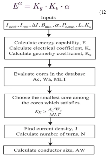
To calculate the approximate size of the magnetic component, the core geometry approach is utilized. To estimate thecore size, several parameters such as peak current (Ipeak), rmscurrent (Irms), maximum flux density (Bmax), regulation (α),maximum output power (Po,max), required inductance (L),and window utilization factor (Ku) should be determined. αis defined as the ratio of the voltage drop across the inductorto the output voltage and is related with the copper losses.The energy handling capability, i.e., E, is a function of α,core geometry coefficient Kg, and an electrical coefficient Ke,which is determined by the magnetic and electrical conditions.Thus
(12)
Fig. 8. Flowchart of the inductor design algorithm based on the core geometry estimation approach.
Where E is 0.5LI 2peak. The electrical coefficient is a function ofthe magnetic and electrical quantities as
(13) The estimation approach is based on finding and evaluatingKg. Some core manufacturers directly provide the Kg[cm5]value for each core, whereas most of the manufacturers justprovide area product AcWa[cm4], where Ac and Wa denotecross-sectional and winding areas, respectively. The relationbetween the area product and Kg can be expressed as
(14) Where MLT is the mean length per turn. The current density canbe extracted from the maximum flux density and area product as
(15) The current density dictates the wire size, which is
(16) Based on the given wire size and winding area, the number ofturns can be calculated as
(17) The flowchart of the inductor core selection is presented in
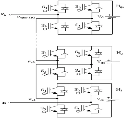
MULTILEVEL INVERTER
Single-phase cascade multilevel inverter topology. The number of levels in the output phase voltage and line voltage are 2s+1 and 4s+1 respectively, where s is the number of H-bridges used per phase. For example, three H-bridges, five H-bridges and seven H-bridges per phase are required for 5-level, 7-level and multilevel inverter respectively. a typical waveform produced by 5-level CMLI. The magnitude of the ac output phase voltage is the sum of the voltages produced by H-bridges.
INDUCTION MOTOR (IM)
An induction motor is an example of asynchronous AC machine, which consists of a stator and a rotor. This motor is widely used because of its strong features and reasonable cost. A sinusoidal voltage is applied to the stator, in the induction motor, which results in an induced electromagnetic field. A current in the rotor is induced due to this field, which creates another field that tries to align with the stator field, causing the rotor to spin. A slip is created between these fields, when a load is applied to the motor. Compared to the synchronous speed, the rotor speed decreases, at higher slip values. The frequency of the stator voltage controls the synchronous speed. The frequency of the voltage is applied to the stator through power electronic devices, which allows the control of the speed of the motor. The research is using techniques, which implement a constant voltage to frequency ratio. Finally, the torque begins to fall when the motor reaches the synchronous speed. Thus, induction motor synchronous speed is defined by following equation,
Where f is the frequency of AC supply, n, is the speed of rotor; p is the number of poles per phase of the motor. By
varying the frequency of control circuit through AC supply, the rotor speed will change.
A. Control Strategy of Induction Motor
Power electronics interface such as three-phase SPWM inverter using constant closed loop Volts l Hertz control scheme is used to control the motor. According to the desired output speed, the amplitude and frequency of the reference (sinusoidal) signals will change. In order to maintain constant magnetic flux in the motor, the ratio of the voltage amplitude to voltage frequency will be kept constant. Hence a closed loop Proportional Integral (PI) controller is implemented to regulate the motor speed to the desired set point. The closed loop speed control is characterized by the measurement of the actual motor speed, which is compared to the reference speed while the error signal is generated. The magnitude and polarity of the error signal correspond to the difference between the actual and required speed. The PI controller generates the corrected motor stator frequency to compensate for the error, based on the speed error.
V.MATLAB/SIMULATION RESULTS
Fig 9Matlab/simulation circuit if none isolated bidirectional buck/boost converters.
(a)
(c)
Fig 10 simulation waveforms for TLC boost mode when d = 0.25 (Vin = 90 V, Vo = 120 V, Po = 700 W). (a) Inductor voltage and current. (b) Voltages across S2 and S3. (c) Input voltage, output current, voltages
across S1 and S4.
(a)
(b)
(c)
Fig 11 simulation waveforms for TLC boost mode when d = 0.48 (Vin = 67 V, Vo = 130 V, Po = 500 W). (a) Inductor voltage and current. (b) Voltages across S2 and S3. (c) Input voltage, output current, voltages
across S1 and S4
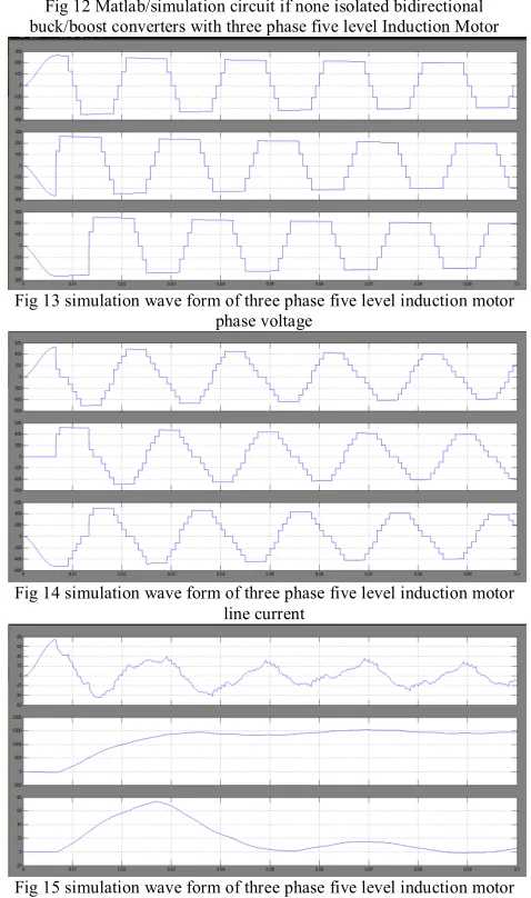
Fig 12 Matlab/simulation circuit if none isolated bidirectional buck/boost converters with three phase five level Induction Motor
Fig 13 simulation wave form of three phase five level induction motor phase voltage
Fig 14 simulation wave form of three phase five level induction motor line current
Fig 15 simulation wave form of three phase five level induction motor stator current, speed and torque
VI.CONCLUSION
REFERENCES
[1]. Serkan Dusmez, Student Member, IEEE, Amin Hasanzadeh, Member, IEEE, and Alireza Khaligh, Senior Member, IEEE” Comparative Analysis of Bidirectional Three-Level DC–DC Converter for Automotive Applications” IEEE Transactions On Industrial Electronics, Vol. 62, No. 5, May 2015
[2] M. Ortuzar, J. Moreno, and J. Dixon, “Ultra capacitor-based auxiliary energy system for an electric vehicle: Implementation and evaluation,” IEEE Trans. Ind. Electron., vol. 54, no. 4, pp. 2147–2156, Aug. 2007.
[3] O. Laldin, M. Moshirvaziri, and O. Trescases, “Predictive algorithm for optimizing power flow in hybrid ultra capacitor/battery storage systems for light electric vehicles,” IEEE Trans. Power Electron., vol. 28, no. 12, pp. 3882–3895, Aug. 2013.[4] I. Aharon and A. Kuperman, “Topological overview of powertrains for battery-powered vehicles with range extenders,” IEEE Trans. Power Electron., vol. 26, no. 3, pp. 868– 876, Mar. 2011.
[5] A. Khaligh and Z. Li, “Battery, ultracapacitor, fuel-cell, hybrid energy storage systems for electric, hybrid electric, fuel cell, plug-in hybrid electric vehicles: State-of-art,” IEEE Trans. Veh. Technol., vol. 59, no. 6, pp. 2806–2814, Jul. 2010.
[6] D. Rotenberg, A. Vahidi, and I. Kolmanovsky, “Ultracapacitor assisted powertrains: Modeling, control, sizing, the impact on fuel economy,” IEEE Trans. Control Syst. Technol., vol. 19, no. 3, pp. 576– 589, May 2011.
[7] W.-S. Liu, J.-F. Chen, T.-J. Liang, R.-L. Lin, and C.-H. Liu, “Analysis, design, control of bidirectional cascaded configuration for a fuel cell hybrid power system,” IEEE Trans. Power Electron., vol. 25, no. 6, pp. 1565–1575, Jun. 2010.
[8] J. Jia, G. Wang, Y. T. Cham, Y. Wang, and M. Han, “Electrical characteristic study of a hybrid PEMFC and ultra capacitor system,” IEEE Trans. Ind. Electron., vol. 57, no. 6, pp. 1945–1953, Jun. 2010. [9] M. H. Todorovic, L. Palma, and P. N. Enjeti, “Design of a wide input range DC–DC converter with a robust power control scheme suitable for fuel cell power conversion,” IEEE Trans. Ind. Electron., vol. 55, no. 3, pp. 1247–1255, Mar. 2008.
[10] A. Emadi, K. Rajashekara, S. S. Williamson, and S. M. Lukic, “Topological overview of hybrid electric and fuel cell vehicular power system architectures and configurations,” IEEE Trans. Veh. Technol., vol. 54, no. 3, pp. 763–770, May 2005.
[11] J. Bauman and M. Kazerani, “A comparative study of fuel-cell– battery fuel-cell–ultra capacitor and fuel-cell–battery–ultra capacitor vehicles,” IEEE Trans. Veh. Technol., vol. 57, no. 2, pp. 760–769, Mar. 2008.
[12] P. Thounthong, V. Chunkag, P. Sethakul, B. Davat, and M. Hinaje, “Comparative study of fuel-cell vehicle hybridization with battery or super capacitor storage device,” IEEE Trans. Veh. Technol., vol. 58, no. 8, pp. 3892–3904, Oct. 2009.