ISSN (Print) : 2320 – 3765 ISSN (Online): 2278 – 8875
I
nternational
J
ournal of
A
dvanced
R
esearch in
E
lectrical,
E
lectronics and
I
nstrumentation
E
ngineering
(An UGC Approved Journal)
Website: www.ijareeie.com
Vol. 6, Issue 8, August 2017
Multiband Microstrip Antenna for Software
Defined Radio/Cognitive Radio based Wireless
Communication Systems
Sharanagouda N Patil*1, P.V.Hunagund2, R.M.Vani3
Research Scholar, Dept. of P.G. Studies and Research in Applied Electronics, Gulbarga University, Kalaburagi, India 1
Professor, Dept. of P.G. Studies and Research in Applied Electronics, Gulbarga University, Kalaburagi, India 2
Professor, Dept. of USIC, Gulbarga University, Kalaburagi, India 3
ABSTRACT:| With the stupendousx advancements in wireless communications, there is a increasing demand for small, low-cost, easy-to- fabricateaa, multibandx and wideband antennas for use in commercial communications systems. The fact that different wireless standards, such as WLAN and WiMAX, use different operation bands push the needs for terminal antennas that are multiband and/or wide band. In this paper, a low-cost multiband micro strip printed-circuit-board (PCB) antenna that employs Kochzz fractal geometry is designed, simulated and demonstratedx. The antenna is fabricated on a 1.6 mm-thick FR4-epoxy substrate with the dimension 4.0 cm*4.5 cm, with micro strip-line feeding and has a partial ground plane. The proposed antenna is simulated using the Finite-Element Method software ANSYS HFSS for three different switching casesx and the return loss in dB is measured for each case. It is revealed that the antenna can operate in the bands of several applications including Wi-Fi, WiMAX as well as a portion of the UWB range. This is a prototype antenna designed for Software Defined Radio/Cognitive Radio applications. The radiation patterns are agreeably Omni directional across the antennas desired operational frequency bands.
KEYWORDS
:
Multiband, Micro strip, PCB, SDR, switchingI.INTRODUCTION
The tremendous advancementss in wirelessx communications, there is an increasing demand for miniature, low-cost, easy-to-fabricateaa, multiband and wideband antennasaa for usea in wireless communications systems. As a partsa of an effort to further enhanceffmodern communications systems technology, researchers have been studying different approaches for creating novel and innovative antennas [1]. The approacha adopted in this paper combines fractal geometry and reconfigurablityw in order to come up with a new antenna design suitable for several wireless applications.
ISSN (Print) : 2320 – 3765 ISSN (Online): 2278 – 8875
I
nternational
J
ournal of
A
dvanced
R
esearch in
E
lectrical,
E
lectronics and
I
nstrumentation
E
ngineering
(An UGC Approved Journal)
Website: www.ijareeie.com
Vol. 6, Issue 8, August 2017
self-similar fractals affect the electromagnetic propertyaa of antennas created on the basis of these geometries, and that Kochzz fractal antennas are multiband structures.
Figure 1: The first four iterations of the standard Kochzz Fractal
Reconfigurablity in antenna systems is a desired feature that has recentlya received significant attention in developingsssnovel and pioneeringssmultifunctional antenna designs. Compared to conventional antennas, reconfigurableaa antennas provide the ability to dynamically adjust various antenna parameters. The active tuning of such antenna parameters is typically achieved by manipulating a certainaa switching behavior. Reconfigurable antennas reduce any adverse effects ssresulting from inter channel/Co-channel interference and jamming. In addition, they have a remarkable characteristic of achieving diversity in operation, meaning that one or multiple parameters, including operating frequency, radiation pattern, gain and/or polarization, can be reconfigured with a single antenna.
Electronic, mechanical or optical switching may be engaged with reconfigurable antennas [7]. Electronic switching is analyzed using lumped components such as PIN diodes, FET transistors or RF MEMS switches Compared to PIN diodes RF MEMS switches have better performance in terms of isolation, power consumption, insertion loss and linearity [8].
II.ANTENNA GEOMETRY
ISSN (Print) : 2320 – 3765 ISSN (Online): 2278 – 8875
I
nternational
J
ournal of
A
dvanced
R
esearch in
E
lectrical,
E
lectronics and
I
nstrumentation
E
ngineering
(An UGC Approved Journal)
Website: www.ijareeie.com
Vol. 6, Issue 8, August 2017
Fig.2a:Geometry of Antenna Fig 2b:Top View Fig 2c:Bottom view Figure 2: Kochz fractal reconfigurable micro strip antenna structure.
Two pairs of RF switches are mounted across the slot, as indicated in Figure 3. A switch in RF systems can be represented either by a resistor to act as a short circuit(ON) or by a capacitor to act as an open circuit(OFF). Therefore, the simplest way to demonstrate an RF switch for use in this design is to construct a 150um2*150um2 rectangular strips that has the same dimensions of those presented in [9]. Hence, an OFF state is represented by taking this rectangular strip out of the antenna, and mounting it again in the same location represents its ON state, as depicted in Fig. 3. This method for representing RF MEMS was used in [9]. RF-MEMS are known to possess good performance in terms of isolation and insertion loss. So, representing these by including or omitting copper strips of the same size is considered valid.
Case 1:All switches OFF Case 2: S1,S2’ ON Case3: S2,S2’ ON
ISSN (Print) : 2320 – 3765 ISSN (Online): 2278 – 8875
I
nternational
J
ournal of
A
dvanced
R
esearch in
E
lectrical,
E
lectronics and
I
nstrumentation
E
ngineering
(An UGC Approved Journal)
Website: www.ijareeie.com
Vol. 6, Issue 8, August 2017
Although 4 switches are used for the operation, only two switching conditions are selected, as listed in Table 1. These dual switching cases were enough to introduce sought-after frequency bands.
Table 1: Switching state for three cases
Case S1, S1’ S2, S2’
Case 1 OFF OFF
Case 2 ON OFF
Case 3 OFF ON
III. RESULTS AND DISCUSSION
The design simulated and analysed in this paper is done using ANSYS HFSS [10] Finite-Element Method (FEM) EM simulator.
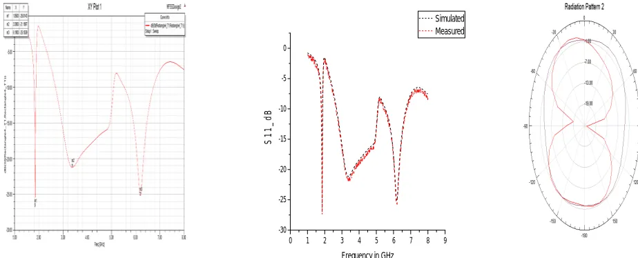
The selected design was used in a reconfigurable scheme after optimizing the locations of the switches. The simulated return loss plots for three cases are given in the Figures 4-6.The ANSYS HFSS-computed gain patterns in the X-Z and Y -Z planes, for each case, are shown in Figures 6-8.
0 1 2 3 4 5 6 7 8 9 -30
-25 -20 -15 -10 -5 0
S
1
1
_
d
B
Frequency in GHz
Simulated Measured
Figure 4: Return loss when all the switches are OFF
ISSN (Print) : 2320 – 3765 ISSN (Online): 2278 – 8875
I
nternational
J
ournal of
A
dvanced
R
esearch in
E
lectrical,
E
lectronics and
I
nstrumentation
E
ngineering
(An UGC Approved Journal)
Website: www.ijareeie.com
Vol. 6, Issue 8, August 2017
0 1 2 3 4 5 6 7 8 9 -25
-20 -15 -10 -5 0
S
1
1
_
d
B
Frequency in GHz
Measured Simulated
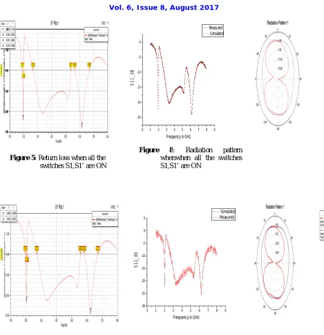
Figure 5: Return loss when all the switches S1,S1’ are ON
Figure 8: Radiation pattern whenwhen all the switches S1,S1’ are ON
0 1 2 3 4 5 6 7 8 9 -30
-25 -20 -15 -10 -5 0 5
S
1
1
_
d
b
Frequency in GHz
Simulated Measured
ISSN (Print) : 2320 – 3765 ISSN (Online): 2278 – 8875
I
nternational
J
ournal of
A
dvanced
R
esearch in
E
lectrical,
E
lectronics and
I
nstrumentation
E
ngineering
(An UGC Approved Journal)
Website: www.ijareeie.com
Vol. 6, Issue 8, August 2017
Figure 10: 3D-Polar plot of the radiation characteristics
Figure 10: VSWR plot
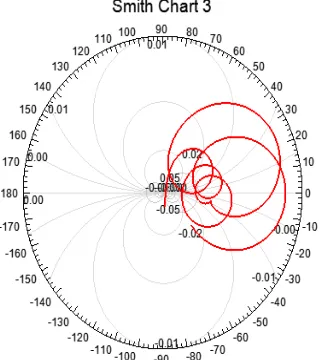
The impedance matching is also analysed using smith chart and found to be within the desired bounds in the frequency of operation.
ISSN (Print) : 2320 – 3765 ISSN (Online): 2278 – 8875
I
nternational
J
ournal of
A
dvanced
R
esearch in
E
lectrical,
E
lectronics and
I
nstrumentation
E
ngineering
(An UGC Approved Journal)
Website: www.ijareeie.com
Vol. 6, Issue 8, August 2017
The three cases result in omnidirectional patterns with equal radiation in the X-Z plane and a figure of 8-shaped pattern corresponding to a 3D pattern shape of a doughnut. This result is expected since the proposed antenna is a printed monopole.
VI.CONCLUSION
An active element integrated micro strip antenna design approach which combines fractal shapes and electronic switching was proposed in this article. The planned design is easy to fabricate, economical and easy integration with MMIC circuits, and multiband/wideband in operation. The antenna is based on a U-slot rectangular patch. Kochzfractal geometry was selected to the patch surface and slot sides to increase the resonant electrical length of the antenna without increasing its overall dimension, thus leading to resonance at a desired lower frequency.
Reconfigurability is achieved by integrating RF switches at selected locations across the slot. Three switching scenarios were selected, and these demonstrated a clear frequency selectivity of the antenna, as shown by simulated return loss results. These antennas are a suitable candidate for the cognitive radio and Software defined radio applications.
REFERENCES
[1]. A. Romputtal and C. Phongcharoenpanich, "Frequency reconfigurablex multiband antenna with embedded biasing network," in IET Microwaves, Antennas & Propagation, vol. 11, no. 10, pp. 1369-1378, 8 16 2017.2.
[2.]. Liu, W. C., W. R. Chen, and C. M. Wu, Printed double S-shaped monopole antenna for wideband and multiband operation of wireless communications," IEE Proc.-Microw. Antennas Propag., Vol. 151, No. 6, 473-476, December 2004.
[3]. R. J. Chitra and V. Nagarajan, "Design and development of Kochzz fractal antenna," 2016 International Conference on Communication and Signal Processing (ICCSP), Melmaruvathur, 2016, pp. 2294-2298.
[4]. Krupeninss, S. V., Modeling of fractal antennas," Journal of Communications Technology and Electronics, Vol. 51, No. 5, May 2006.
[5]. S. N. Patil, P. V. Hungund, R. M. Vani and H. V. M. Reddy, "Reconfigurable antenna for cognitive radio application using slot and parasitic patch," 2016 International Conference on Electrical, Electronics, Communication, Computer and Optimization Techniques (ICEECCOT), Mysuru, 2016, pp. 146-150.
[6]. Krishna, D. D, C. K. Anandana, P. Mohanan, and K. Vasudevan, CPW-fed Kochzzfractal slot antennaa for WLAN-WiMAX applications," IEEE Antennas and Wireless Propagation Letters, Vol. 7, 389-392, 2008.
[7]. Anagnostosus, D. E., J. Pappolymerou, M. M. Tentzeris, A printeed logperiodic Koch-dipole arraay ," IEEE Antennas and Wireless Propagations Letters, Vol. 7, 456-460, 2oo8.
[8] .Xiaao, G. and S. Zhu, Novel fractal and MEMS fractal antennas," International Conference on Microwave and Millimeter Wave Technology, 1-4, April 18-21, 2008.
[9]. Kingsley, N., D. E. Anagnostou, M. Tentzeris, and J. Papapoly- merou, RF MEMS sequentially recon¯gurable sierpinski antenna on a Fexible organic substrate with novel DC-biasing technique," Journal of Microelectromechanical Systems, Vol. 16, No. 5, 1185-1192, October 2007.