A New Single-Layer Reflectarray Using Circular Patch
with Semicircular Ring Slots
Yang Liu1, 2, Hongjian Wang1, 2, *, Fei Xue1, 2, and Xingchao Dong1, 2
Abstract—A single-layer reflectarray antenna using circular patch with four semicircular ring slots is proposed in this paper. By changing the diameter of the circular patch, the proposed phasing element can realize phase range about 500 degrees with relatively stable reflection magnitude. Besides, the reflection phase curve with smooth slope is almost linear. Based on the good phase response, a 421-element reflectarray is designed, simulated and fabricated. The measured results show that 1.5-dB gain bandwidth can attain 24% at the center frequency of 15 GHz.
1. INTRODUCTION
Reflectarray antenna has attracted much attention due to its low profile, low cost, versatile radiation characteristics and high gain performance [1]. A number of outstanding reflectarray designs are developed to achieve these good merits in recent years. Most of the phase-shift elements used in the reflectarray antennas are patches [2], rings [3], stubs [4], slots [5] and their combinations [6–8]. A certain shifting phase can be generated by adjusting the dimension of key part or rotating the whole element by a certain angle. All the above approaches can realize relatively good performances.
According to the number of metallic layers except the ground, the reflectarray can be divided into multilayer and single-layer configurations [9]. Given the high cost and high loss of multilayer implementation, the layer configuration seems a better choice in fabrication. But in some single-layer designs [10, 11], a thick air or foam single-layer is added between the substrate and the ground plane with the aim to eliminate rapid phase change, which will increase complexity and uncertainty in assembly. As a result, using only one kind of dielectric material as the substrate is a more appealing way in the design of a reflectarray antenna.
In [12], a detailed study of the characteristics of single patch and ring element demonstrates that the two elements can achieve a slower phase curve slope by using a thicker substrate but fails to realize adequate phase range of 360◦. To continue utilizing the simple patch or ring element, the structure needs to be redesigned or integrated with other structure forms to get more phase-shift range. The rectangular patch with a four rectangular slots structure called Malta Cross is shown in [13] to obtain large bandwidth, but two independent parameters will affect the reflection phase range. The circular patch mentioned in [14] has the advantages in phase response for its independence of the azimuth angle which will result in less phase error and realize high efficiency. The circular patch with slots introduced in [15] obtains large phase range but fails to smooth the phase curve. However, there are few papers diving into the basic phasing element to realize desired goals.
In this paper, a new single-layer reflectarray antenna using a circular patch with four semicircular ring slots is presented. A comprehensive parametric study of the phasing element is performed to achieve its linear phase characteristic. By adjusting the dominant diameter of circular patch, about
Received 18 January 2017, Accepted 22 February 2017, Scheduled 7 March 2017 * Corresponding author: Hongjian Wang ([email protected]).
500◦ phase range can be realized, which satisfies the design requirement. Then the reflectarray element is designed and carefully analyzed. In order to validate the element performance, the reflectarray with square aperture is designed, fabricated and measured.
2. ELEMENT DESIGN
The basic geometry of the proposed single-layer reflectarray element is depicted in Fig. 1. This element can be seen as the improvement of circular patch, and its main structure consists of a circular patch with four semicircular ring slots. The angle between every two adjacent slots is 90◦. The material F4B with relative permittivity (r) of 2.2 is adopted as the substrate. The phase and magnitude performances of the element under normal incidence are analyzed using HFSS with Floquet port excitations and master-slave boundaries.
The parameters and their relationships of the element are as follows. The element grid spacing Ls is 10.4 mm, which equals 0.52λ0. λ0 is the wavelength of microwave in free space at the center frequency of 15 GHz. The circular patch diameter D is the dominant control parameter, which will
(a) (b)
Figure 1. Geometry of the proposed element. (a) Top view. (b) Side view.
(a) (b)
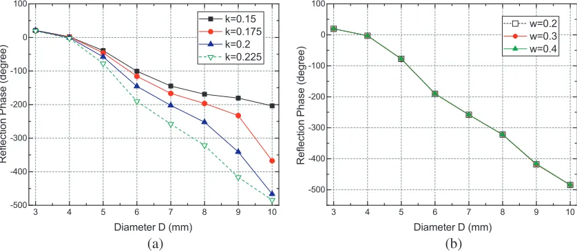
affect the reflection phase in a large degree. R1 is the radius of the outer circle of the semicircular ring slot and meetsR1=k·D, wherekis the constant ratio that determines the outer circle radius, and its optimization result is shown in Fig. 2(a). The result suggests that the phase response is approximately linear, and the phase range is relatively large whenk= 0.225. The radius of the inner circleR2 satisfies R2 =R1−s. The slot widthsis set at 0.3 mm because the simulation results show that the reflection phase curves overlap with each other whens is at certain values within reasonable range, as shown in Fig. 2(b). Besides, the inner circle of the semicircular ring slot is always tangent to the circular patch when bothR1 and R2 vary with the change of diameter D.
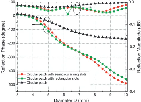
To demonstrate the good performance of the proposed design, the conventional circular patch and circular patch with four rectangular slots, displayed in Fig. 3(a) and Fig. 3(b), are also designed and simulated. The rectangular slot has the same width as the semicircular ring slot which is 0.3 mm, and the length of rectangular slot is 0.45D, same as the diameter of the outer circle of the semicircular ring slot. The comparisons of reflection phase and magnitude responses are given in Fig. 4. Though all the three designs have high reflection magnitude, the reflection phases are quite different. The circular patch element can reach only 170◦ when substrate height is 3 mm. The circular patch with four rectangular slots can achieve nearly 450◦ phase shift while the proposed unit cell can realize phase range about 500◦. Actually, the last two designs both meet the phase shifting requirement of 360◦ so that both of them
(a) (b) (c)
Figure 3. The comparison of three different elements. (a) Circular patch. (b) Circular patch with rectangular slots. (c) Circular patch with semicircular ring slots.
Figure 5. The reflection performances for different substrate heights.
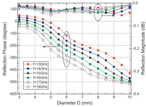
Figure 6. The reflection performances for different frequencies.
Figure 7. The reflection performances for different incident angles.
Figure 8. The phase distribution on reflectarray aperture.
can be used to design reflectarray. But considering the slight discrepancy that the phase curve of the proposed element has better linearity, the circular patch with four semicircular ring slots is selected as the basic element.
Single-layer realization without extra air or foam layer means that the height of the substrate should be taken into consideration. The reflection phases and magnitudes of the element with different substrate heightsH are illustrated in Fig. 5. It is clear that the thicker the substrate is, the smoother the phase curve is. Since the reflection magnitudes remain relatively stable during the changing of substrate height, it is conjectured that the reflection magnitude is independent of the substrate height to some extent. When H is more than 3 mm, the slope of the phase curve may satisfy the linearity requirement. Considering the weight and cost, H= 3 mm is chosen as the substrate height.
(a) (b)
Figure 9. Photograph of the fabricated prototype. (a) Reflectarray. (b) Antenna under test.
Figure 10. Measured aperture phase distribution at 15 GHz.
(a) (b) (c)
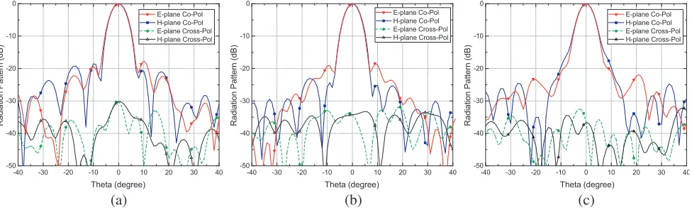
Figure 11. The simulated radiation patterns. (a) 14 GHz. (b) 15 GHz. (c) 16 GHz.
affect the reflection magnitude when the angle and diameter are with large values. In fact, the magnitude loss is still within acceptable range. Therefore, the proposed element is suitable for reflectarray design.
3. ARRAY DESIGN AND PERFORMANCE
To verify the validity of the proposed element of circular path with four semicircular ring slots, a reflectarray prototype needs to be designed. The square aperture D of the reflectarray is 218.4 mm, which means that the antenna is composed of 21×21 elements. The focal distance F from the surface of the reflectarray to the horn phase center satisfiesF = 0.8D. The simulated phase distribution of the reflectarray without the phasing element etched on the substrate is shown in Fig. 8. Based on the phase distribution and reflection phase curve, a reflectarray antenna is fabricated using the proposed element, as shown in Fig. 9(a). A pyramidal horn antenna with 15.2 dB gain is used as feed source, and normal incidence is adopted.
(a) (b) (c)
Figure 12. The measured radiation patterns. (a) 14 GHz. (b) 15 GHz. (c) 16 GHz.
Figure 13. Measured gain and aperture efficiency versus frequency.
It can be observed from the simulated results that the sidelobe level (SLL) in E-plane is −18 dB and
−21 dB inH-plane. The cross polarization level (CPL) is about−35 dB. The measured gain is 25.2 dBi at center frequency of 15 GHz. There are distinct differences between the simulated and measured radiation patterns. For one reason, the instability of material properties may lead to unequal paths between the top patch and ground plane so that the real phase shift may be different from the initial design. For another, the blockage and misalignment of the feed horn may bring error in focal length, which may cause the deformation of radiation patterns. The measured gain and aperture efficiency are shown in Fig. 13. It can be seen that the measured 1.5-dB gain bandwidth is 24% (from 13.2 GHz to 16.8 GHz), and the 3-dB gain bandwidth is 32.7% (from 12.7 GHz to 17.6 GHz). The aperture efficiency is 22% at 15 GHz.
4. CONCLUSION
REFERENCES
1. Huang, J. and J. A. Encinar,Reflectarray Antennas, John Wiley and Sons Inc., NJ, 2008.
2. Guo, L., P. K. Tan, and T. H. Chio, “A simple method to realize polarization diversity in broadband reflectarrays using single-layered rectangular patch elements,”Proc. IEEE Int. Symp. Antennas and Propagation USNC/URSI National Radio Science Meeting, 2161–2162, Jul. 2015.
3. Zhang, F. and J. Zhang, “Design and analysis of a reflectarray using defected double-square rings for microwave application,”Proc. 8th Int. Symp. Computational Intelligence and Design (ISCID), Vol. 2, 594–597, Dec. 2015.
4. Xue, F., H. J. Wang, M. Yi, G. Liu, and X. C. Dong, “Design of a broadband single-layer linearly polarized reflectarray using four-arm spiral elements,” IEEE Antennas and Wireless Propagation Letters, No. 99, 2016.
5. Ortiz-Fuentes, J. A., J. Silva-Montero, J. I. Martinez-Lopez, J. Rodriguez-Cuevas, and A. E. Martynyuk, “Dual-frequency reflectarray based on split ring slots,” IEEE Antennas and Wireless Propagation Letters, No. 99, 2016.
6. Malfajani, R. S. and Z. Atlasbaf, “Design and implementation of a broadband single layer circularly polarized reflectarray antenna,” IEEE Antennas and Wireless Propagation Letters, Vol. 11, 973– 976, 2012.
7. Fakharian, M. M., P. Rezaei, and A. A. Orouji, “A novel reflectarray based on the folded SIR patch-slot configuration,” Proc. 8th European Conf. Antennas and Propagation (EuCAP 2014), 1931–1933, Apr. 2014.
8. Rouzbahani, S., A. Z. Nezhad, and M. M. Ali, “Design of reflectarray with cosecant squared radiation pattern in x-band,”in Proc. 24th Iranian Conf. Electrical Engineering (ICEE), 502–506, May 2016.
9. Deng, R., S. Xu, F. Yang, and M. Li, “A single-layer high-efficiency wideband reflectarray using hybrid design approach,”IEEE Antennas and Wireless Propagation Letters, No. 99, 1–1, 2016. 10. Zarghani, Z. H. and Z. Atlasbaf, “A new broadband single-layer reflectarray antenna,”Proc. 22nd
Iranian Conf. Electrical Engineering (ICEE), 1619–1622, May 2014.
11. Malfajani, R. S. and Z. Atlasbaf, “Design and implementation of a dual-band single layer reflectarray in x and k bands,”IEEE Transactions on Antennas and Propagation, Vol. 62, No. 8, 4425–4431, Aug. 2014.
12. Bialkowski, M. E. and K. H. Sayidmarie, “Investigations into phase characteristics of a single-layer reflectarray employing patch or ring elements of variable size,” IEEE Transactions on Antennas and Propagation, Vol. 56, No. 11, 3366–3372, Nov. 2008.
13. Vita, P. D., A. Freni, G. L. Dassano, P. Pirinoli, and R. E. Zich, “Broadband element for high-gain single-layer printed reflectarray antenna,”Electronics Letters, Vol. 43, No. 23, Nov. 2007.
14. Hasani, H., M. Kamyab, A. Mirkamali, and H. Eskandari, “Reflectarray antenna consisting of circular disk elements: Design and measurement,”Proc. Asia-Pacific Microwave Conf., 1565–1568, Dec. 2010.