FPGA Implementation of DWT-DAA Based Image
Compression
1ARCHITA.S 2KAVYA SHREE.N.K
Dept. of ECE Dept. of ECE VKIT VKIT
Bengaluru-74, INDIA Bengaluru-74,INDIA
[email protected] [email protected]
3ARUN KUMAR.M 4MAHESH.K.N
Dept. of ECE Dept. of ECE VKIT VKIT
Bengaluru-74, INDIA Bengaluru-74, INDIA
[email protected]
Abstract - This paper presents an approach towards VLSI implementation of the Discrete Wavelet Transform
(DWT) along with distributed arithmetic technique for image compression. DWT is a widely used wavelet transformation. DWT transforms image from space domain to frequency domain, where the wavelets are discretely sampled. DWT has various advantages over other image transforms such as image can be represented in multi resolution form, avoids the division of image into non-overlapping blocks, blocking artifacts are avoided to achieve a high compression ratio. In order to reduce complexities of the design, linear algebra view of DWT and IDWT has been used. Image compression is minimizing the size in bytes of a graphics file without degrading the quality of the image to an unacceptable level. The reduction in file size allows more images to be stored in a given amount of disk or memory space. In this paper to speed up the process parallel implementation of the Distributive Arithmetic (DA) algorithm is proposed. This parallel implementation, divides the input data into even samples and the odd samples based on their position. This process reduces the memory size to half due to the symmetric property of the filter coefficients. Functional simulation and performance are analysed using MATLAB and XILINX Software the image will reduced from 512*512 to 256*256.
KEYWORDS - DWT, Image Compression, Image Transform, DAA, IDWT, Wavelet compression and
decomposition.
I. INTRODUCTION
Today's electronic equipment comes with user friendly interfaces such as keypads and graphical displays. As images convey more information to a user, it is many of the equipment today have image displays and interfaces. Image storage on these smaller, handled devices is a challenge as they occupy huge storage space; also image transmission requires higher bandwidth. Hence most of the signal processing technologies today has dedicated hardware that act as coprocessors to compress and decompress images [2].
In this work, a reliable, high speed, low power DWT-IDWT processor is designed and implemented on FPGA which can be used as a co-processor for image compression and decompression. JPEG image compression that is in widespread use today took several years for it to be perfected. Wavelet based techniques such as JPEG2000 for image compression has a lot more to offer than conventional methods in terms of compression ratio.
II. PROPOSED METHODOLOGY
In this paper we propose Image compression using DWT. The coloured Image is selected and it will be converted to Gray scale. The Image is decomposed into coefficients called sub-bands and then the resulting coefficients are compared with a threshold. Finally, the coefficients above the threshold value are encoded with a loss less compression technique. The wavelet basis are primarily linked to the relative scarceness of the wavelet domain for representation of the signal. The Image is compressed using Verilog codes and implemented on MATLAB Software.
A. Discrete Wavelet Transform
needs to be eliminated. The DWT, which is based on sub band coding, is found to yield a fast computation of Wavelet Transform. It is easy to execute and reduces the time and resources required. The discrete wavelet transform uses filter banks for the construction of the multi resolution
time-frequency plane. The Discrete Wavelet Transform analyzes the signal at different frequency bands with different resolutions by decomposing the signal into an approximation and
detail information
[image:2.595.172.423.219.310.2].
Figure 1: One-dimensional Discrete Wavelet Transform
The one-dimensional discrete wavelet transform (DWT) can be described in terms of a filter band as shown in Figure1. An input signal
x[n] is applied to the low pass filter l[n] and to the analysis high-pass filter h[n]. The odd samples of the outputs of these filters arethen discarded, corresponding to a decimation factor of two. The decimated outputs of these filters constitute the reference signal r[k] and the detail signal d[k] for a new-level of decomposition. During reconstruction, interpolation by a factor of two is performed, followed by filtering using the low-pass and high-pass synthesis filters l[n] and h[n]. Finally, the outputs of the two synthesis filters are added together. The computation of the wavelet filter is performed according to the following equations: D0 = D0 + D0 - S0 – S0……… (1)
S0 = S0 + (2 * D0/8)………... (2)
Di = Di + Di – Si – Si+1... (3)
Si = Si + ((Di-1 + Di) / 8)………….. (4)
In the above equations, Di and Si are
odd and even pixel values taken from one row or column respectively. In image compression,
one row or column of an image is regarded as a signal. Figure.1 shows the row and column formation at level 1 for a 512 X 512 pixel image.
B. DAA Concept
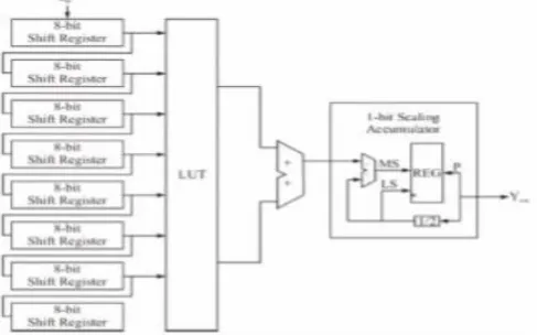
Distributed Arithmetic (DA) is a technique to implement digital signal processing (DSP). However, traditional lookup table (LUT) based DA concept contain one or more carry propagation chains in the critical path that entire design can run fast. Distributed Arithmetic (DA) provides an approach for multiplier-less implementation of DSP systems. It is an algorithm that can perform multiplication with lookup table (LUT) based schemes. DA specifically targets the sum of products computation that is found in many of the important DSP filtering and frequency transforming functions. Combined with Xilinx FPGA lookup table architecture, the DA algorithm was shown to produce very efficient filter designs[7].
[image:2.595.169.413.604.756.2]All the Pixels value cannot be transformed at a time. Each pixel will be divided into 8 bits as shown in the Figure 2 and then stored in Mux. Multiplication is performed using logic adders and logic registers. The 8 bits is then sent to row and vertical operation. All the processed pixels values are stored in the controller. The processed image will be of 1D, thus this is converted back to 2D
image using MATLAB. The 2D processed image can be seen in the output.
III.WAVELET COMPRESSION AND DECOMPOSITION
[image:3.595.118.444.239.328.2]The procedure is as follows: wavelet has two functions wavelet and scaling function. They act like a low pass filter and a high pass filter
Figure 3: Wavelet Decomposition
The decomposition of the signal into different frequency bands is simply obtained by successive high pass and low pass filtering of the time domain signal [3]. This filter pair is called the analysis filter pair. In Figure 3, first the low pass filter is applied for each row of data, thereby getting the low frequency components of the row. But since the low pass filter is a half band filter, the output data contains frequencies only in the first half of the original frequency range. By Shannon's Sampling Theorem, they can be sub-sampled by two, so that the output data now contains only half the original number of samples. Now, the high pass filter is applied for the same row of data, and similarly the high pass components are separated. Digital image is represented as a two-dimensional array of coefficients, each
coefficient representing the brightness level in that point. It can be differentiated between coefficients as more important ones, and lesser important ones. Most natural images have smooth colour variations, with the fine details being represented as sharp edges in between the smooth Variations.
The low frequency components (smooth variations) constitute the base of an image, and the high frequency components (the edges which give the details) add upon them to refine the image ones, and lesser important ones. Most natural images have smooth colour variations, with the fine details being represented as sharp edges in between the smooth there by giving a detailed image. Digital image compression is based on the ideas of sub-band decomposition or DWT.
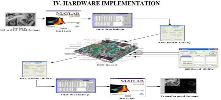
[image:3.595.114.476.575.740.2]IV. HARDWARE IMPLEMENTATION
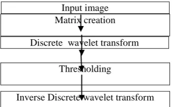
Figure 5: Flowchart DWT Based Image compression Implementation
The flow diagram of how the implementation is done is as shown in the Figure 4. The FPGA board is then configured with the bit file of the „right_ram_bank.bit‟ so that the right memory bank is read. The XSVSRAM utility then reads the right SRAM bank and transfers the memory file to „hex.bit‟ file on the PC. This hex file is converted to a PGM image file by the MATLAB Program by adding suitable image headers. This wavelet transformed PGM image can be viewed and analyzed by the PGM viewer utility in the MATLAB PGM toolbox. The input hex.bit is loaded and then simulated. In the same way the output hex.bit will be created automatically and the compressed image will be displayed on the screen.
A. MATLAB Implementation –The flow
diagram of how it will be Implemented in
MATLAB TOOL is as shown in the figure 5. 2D DWT and IDWT together is implemented with Thresholding in MATLAB. In the DWT part the input data will be transferred from time domain to scale domain. Then in thresholding part some of the coefficients will be set to zero and in the IDWT part the coefficients will be transferred back into time domain. The block diagram of MATLAB implementation is shown in the figure 4.While implementing the algorithm in MATLAB the matrix multiplication method has been used [9]. We have tested the as the image input file and also randomly chosen image co-efficient for MATLAB simulation. The proposed method achieved satisfactory result in MATLAB and proceed to the next stage where we translate the code into Verilog.
[image:4.595.211.386.565.674.2]Discrete wavelet transform
Figure 6: Simulation waveform of Image Compression
V. RESULTS
The Proposed Methodology is implemented using Xilinx is followed by the
generation of the hex.bit file as shown in figure 6. The hardware implementation is carried out by programming the FPGA through the Input image
Matrix creation
Thresholding
parallel port. Equivalent Verilog and MATLAB programs are coded to evaluate the
execution time taken by the software implementation.
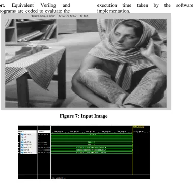
[image:5.595.124.504.122.488.2]Figure 7: Input Image
Figure 8: Compressed Image
The above Figures 7 and figure 8 shows the Image compression and the original Image reconstructed back as same as the Input Image using the Verilog Codes and Simulated in MATLAB simulation.This technique is analyzed using MATLAB software. Images are barbara.pgm is Remote sensing image (single band) of 512 x 512 size is taken as an input image. The Input Image is converted to hex.bit and loaded then it is simulated using verilog
code and the compressed Output image will also be converted to hex.bit. When the output is converted to hex.bit then the simulation is done in MATLAB Software the compressed Image of the Input Image (512*512) can be seen as the output (256*256) as simulation result. The Device Utilization summary table and Execution time in both MATLAB and XILINX software is as shown in the below tables 1 and 2:
Table 1: Device Utilization summary
Device Utilization Summary
Slice Logic Utilization Used Available Utilization
Number of slice Registers 315 18,224 1%
Number used as Flips Flops 280 Number used as Latches 0
Table 2: Execution Time in MATLAB and XILINX
Unit
Picture Format Pixel 512*512 256*256
MATLAB Execution Time Sec 13.008 1.960
VI. CONCLUSION
This paper introduced the basic wavelet theory used for wavelet transform based image compression. FPGA based hardware design methodology is presented. DWT algorithm using the Debauchies wavelet is studied and implemented in software. The algorithm is behaviorally described using Verilog. After successful verification the design is synthesized and tested on prototype hardware. Performance analysis of the harware design with respect to software is evaluated. It is seen that the hardware speed up obtained is several times compared to software implementations. This framework for an FPGA-based DWT system would allow a image processing application developer to generate FPGA configurations for DWT at a high level rather than spending considerable time learning and designing at a gate and routing level. Thus, the end-user will benefit from the high performances of FPGA devices while designing at a high level with familiar tools.The results are promising when compared to software; however, further work needs to be done towards the extension of the system to handle different arithmetic representation, different wavelet analysis and synthesis schemes along with different architectures.
REFERENCES
[1] M.J. Sebastian Smith, “Application-Specific Integrated Circuits”, Addison-Wesley professional (publisher), 1st edition, 1040 pages, June 20, 1999.
[2] U. Meyer-Baese, Digital Signal Processing with Field Programmable Gate Arrays, New York: 2001, pp.61-77.
[3] M. Nagabushanam, Cyril Prasanna Raj p, S. Ramachandran, “Design and FPGA Implementation of Modified Distributive Arithmetic Based DWT – IDWT Processor for Image Compression”, Vo.42, No. 2, pp. 478-492,2010.
[4] S.Mallat, “Multi frequency channel decompositions of images and wavelet models”, IEEE Transaction Acoust., Speech, Signal Process., vol.37, no. 12, pp. 2091-2110, Dec. 1989.
[5] J. M. Shapiro, "Embedded image coding using zero trees of wavelet coefficients," IEEE Trans. Signal Processing, vol. 41, pp. 3445-3462, Dec. 1993.
[6] MajidRannani and Rajan Joshi, "An Overview of the JPEG2000 Still Image Compression Standard", Signal Processing, Image Communication, vol. 17, pp. 3-48, 2002.
[7] Mahesh Goparaju, S Mohan, “Implementation of DWT and IDWT for compression of Image”, International Journal of Scientific and Research Publications, Volume 3, Issue 3, March 2013.
[8] M, Vishwanath, R. M. Owens, and M. 1. Irwin, "VLSI Architectures for the Discrete Wavelet Transform," IEEE Trans. Circuits And Systems II,vol. 42,no. 5,pp. 305316,May. 1995.