UNIVERSITI TEKNIKAL MALAYSIA MELAKA
Electrode Tool Wear Analysis under Various
Cutting Parameters in the Die Sinking Electrical
Discharge Machine (EDM)
Thesis submitted in accordance with the requirements of the
Universiti Teknikal Malaysia Melaka for the Degree of
Bachelor of Manufacturing Engineering (Manufacturing Process)
By
Zariyanti Bte Paijoo
Faculty of Manufacturing Engineering
UTeM Library
!"#$%
& & ' %
( ( ) ( * ( %
+ ( &, -. / , 01".., , /& & 2
+ !3 $..#
& +
( ( ) ( * ( 4 %
5 & +
+ 66666666666666666666666
/ +
* ( ) / ( + $..< = $..#
_____________________________________________________________________
* ' ' & & 9 : %
* > % ?
+
!2 > 2
$2 * >
2 <2 *
2 12 77 %
; & && @ A & 5 *
ELECTRODE TOOL WEAR ANALYSIS UNDER VARIOUS CUTTING
PARAMETERS IN THE DIE SINKING ELECTRICAL DISCHARGE
MACHINE (EDM)
ZARIYANTI BTE PAIJOO
APPROVAL
This thesis submitted to the senate of UTeM and has been accepted as partial fulfillment of the requirements for the degree of Bachelor of Manufacturing Engineering (Manufacturing Process). The members of the supervisory committee are as follow:
………. Main Supervisor
DECLARATION
I hereby, declare this thesis entitled “Electrode Tool Wear Analysis under Various Cutting Parameters in the Die Sinking Electrical Discharge Machine (EDM)” is the
results of my own research except as cited in the reference.
Signature : ………
Author’s Name : ZARIYANTI BT PAIJOO
ABSTRACT
ABSTRAK
DEDICATION
ACKNOWLEDGEMENTS
A special thanks to my Supervisor, Mr. Raja Izamshah B Raja Abdullah for his supervision in doing this project. I greatly appreciate his consistent encouragement, advice and invaluable guidance throughout the project.
I wish to extend my special appreciation to Mr. Hadzley B. Abu Bakar, Mr. Sivarao, Mr. Akramin B. Mohamad and all technicians for their patience, support and comment.
TABLE OF CONTENTS
Abstract………..……….i
Dedication………..ii
Acknowledgement……….iii
Table of Contents………..iv
List of Figures………...………...vii
List of Tables……….ix
Sign and Symbols………..xi
1. INTRODUCTION 1.1 Introduction………..1
1.2 Background of the problem………..2
1.3 Objectives……….2
1.4 Scopes………...3
1.5 Important of the Study………..3
1.6 Expected result……….3
2. LITERATURES REVIEW 2.1 Electrical Discharge Machining (EDM)………...…4
2.2 Die-Sinking EDM……….6
2.3 Principles of Die Sinking EDM………7
2.4 Flushing………8
2.5 Dielectric Fluid………...12
2.6 The Servo Mechanism………13
2.7 Material Removal Mechanism………...14
2.8 Material Removal Rates……….15
2.9.2 Copper………...21
2.10 Material of Workpiece………..22
2.10.1 Stainless Steel 304……….22
2.10.2 Mild Steel……….24
2.10.2.1 Types of Carbon Steel………25
2.10.2.2 Metallurgy………..25
2.11 Dimensional Accuracy……….27
2.12 Parameter Selection in Electrode Tool Wear EDM……….27
2.12.1 Current………...28
2.12.2 Voltage………..29
2.12.3 Spark Gap………..29
2.12.4 Jump Speed………30
2.13 Electrode Tool Wear……….31
2.13.1 Electrode Wear (Graphite and Copper)……….33
2.13.2 Type of Tool Wear………35
2.13.3 Electrode Wear Compensation………..36
2.14 Resolution (Image Analysis Microscope)………37
2.15 Design of Experiments (DOE)……….37
2.15.1 Analysis of Variance (ANOVA)………...39
2.15.2 The 2k Factorial Design……….39
2.16 Conclusion of Literature Review………..39
3. METHODOLOGY 3.1 Introduction………41
3.2 The Design of Experiment Process (DOE)………42
3.2.1 Objective the Experiment………..42
3.2.2 Identification of the Control Factors and Their Level………...42
3.2.3 Identify Suitable Noise Factor/Response………..43
3.2.4 Select the Appropriate Orthogonal Array (OA)………43
3.2.5 Preparation of the Experiment Conducted………46
3.2.5.1 Parameter Setting………..47
3.2.5.2 Specimen Preparation………48
3.2.5.3 Electrode Copper………...48
3.2.5.4 Workpiece Preparation………. 49
3.2.5.5 Conduct the Experiment..………..49
3.2.5.6 Testing ………..51
3.2.5.7 Image Analysis Microscope………..53
3.2.6 Analyzed and Interpreted Results of Experiment Trials………54
3.2.7 Conclusion and Recommendation………..55
3.3 Flow Chart……….55
4. EXPERIMENT PROCEDURE AND SETUP 4.1 Preparation Procedure………57
4.2 Experiment, Equipment and Procedure………..57
4.3 Setup Procedure………..58
4.4 Machining Parameter………..59
5. RESULT AND DISCUSSIONS 5.1 Result and Discussion……….61
5.2 Orthogonal Array Experiment………62
5.3 Normal Probability of Effects Analysis……….64
5.4 Pareto Chart of Effects Analysis………65
5.5 Interaction Plot (data mean) for Electrode Wear………...66
5.6 Main Effect Plot (data mean) for Electrode Wear……… 67
5.7 Pareto Chart of the Standardized Effect……….68
5.8 Cube Plot (data mean) for Electrode Wear……….69
5.9 Balanced ANOVA………..70
5.9.1 Full Factorial Design………..71
5.10 Residual Plot for Electrode Wear……….73
5.11 Mathematical Model……….74
5.11.1 The Functional Relationship Y=f(X)………...75
5.12 Electrode Wear Surface………76
6. CONCLUSION AND RECOMMENDATION 6.1 Conclusion……….80
6.2 Suggestion and Recommendation………..81
6.2.1 More Sample are Taken……….81
6.2.2 Implement using other Workpiece or Electrode Material………..81
6.2.3 Suggestion for Further Study………..81
REFERENCES………...83
APPENDICES
A Work Progress Table for PSM
LIST OF FIGURE
2.1 A Controlled Spark Discharge Removes a Very Small Particles 5
Between Workpiece and Electrode 2.2 A Cutting Tool (electrode) Shaped To the Form of the Cavity 6
2.3 Ram Type EDM Plunge a Tool, Shaped To the Form of the Cavity Required 7
Into a Workpiece 2.4 Method of the Circulating Dielectric Fluid (down through the electrode) 9
2.5 Method of the Circulating Dielectric Fluid (up through the workpiece) 10
2.6 Method of the Circulating Dielectric Fluid (vacuum flow) 10
2.7 Method of the Circulating Dielectric Fluid (by vibration) 11
2.8 Metal-Removal Rate Increase With the Amount of Energy Per Spark 16
2.9 Overcut Chart 27
2.10 The Wear Morphologies of the Machine Electrode 32
2.11 SEM Photographs of (a) Copper Electrode Surface and (b) Brass 33
Electrode after Sinker EDM Machining 2.12 The Difference in Electrode Wear Between Copper and Graphite 34
2.13 Outlines Some Typical EDM Application Results 35
2.14 The Life of the Electrode Depends on its Ability To Resist the Wear 36
Vulnerable Point 3.1 3 Steps in Designing Orthogonal Array 44
3.2 Preparation of the Experiment 46
3.3 Copper Electrode 48
3.4 Workpiece (mild steel AISI 1020) 49
3.5 Vertical Position of Electrode 50
3.6 EDM Die-Sinking (Sodick LN/LQ Series) 51
3.9 Image Analysis Microscope 53
3.10 Flow Chart 56
4.1 Procedure step for equipment setup 58
5.1 Normal probability of the effects 64
5.2 Pareto chart of the effect 65
5.3 Interaction plot (data mean) for electrode wear 66
5.4 Main effect plot (data mean) for electrode wear 67
5.5 Pareto chart of the electrode 68
5.6 Pareto chart for the standardized effect 68
5.7 Cube plot (data mean) for electrode wear 69
5.8 Residual for electrode wear 73
5.9 Experiment 1 with IP(2.5), V(21) and JS(10) 76
5.10 Experiment 2 with IP(7.3), V(21) and JS(10) 77
5.11 Experiment 3 with IP(2.5), V(22) and JS(10) 77
5.12 Experiment 4 with IP(7.3), V(22) and JS(10) 77
5.13 Experiment 5 with IP(2.5), V(21) and JS(20) 78
5.14 Experiment 6 with IP(7.3), V(21) and JS(20) 78
5.15 Experiment 7 with IP(2.5), V(22) and JS(20) 78
LIST OF TABLE
2.1 Properties of Graphite electrodes for EDM 19 2.2 The Specification of Electrode Graphite 20
2.3 The Physical Properties of Copper Electrode 22 2.4 The Room Temperature Mechanical Properties of Stainless Steel 304 24 2.5 Chemical Composition of Stainless Steel Used in Construction 24
2.6 Second Digit of Jump Speed 30
2.7 First digit of Jump speed 30
3.1 Two Level of Processes Parameter 43
3.2 2³ Design Example 44
3.3 Signs of Effects in 2³ 45
3.4 Important Parameter Setting for Copper Electrode 47
3.5 EDM Parameter and Setting Condition 47
4.1 Example of Machining Parameter for Experiment 1 60
5.1 Machining Parameters and Their Level 62
5.2 Experimental Layout Using an L8 Orthogonal Array and Result 63
of Electrode Wear Ratio
5.3 Design Table for Orthogonal Array 71
5.4 EW versus IP and V 71
5.5 Analysis of Variance for EW 72
LIST OF ABBREAVIATIONS, SYMBOLS AND
SPECIALIZED NOMENCLATURE
A - Ampere
ANOVA - Analysis of variance
C - Carbon
CMM - Coordinate measuring machine
cm - Centimeter
DOE - Design of experiment
EW - Electrode Wear
Fe - Ferum
In - Inch
IP - Current
Js - Jump Speed
k - Factor
m - meter
Max - maximum
Min - minimum
Mn - Manganese
MPa - Mega pascal
MRR - material removal rate
min - minute
mm - millimeter
Ni - Nickle
OA - orthogonal array
Si - Silicon
SS - Sum of square
V - Volt
µm - micrometer
µin - microinch
µs - microsecond
- ohm
µ m - micro ohm meter
µ /cm - micro ohm per centimeter
% - percent
ºC - degree celcius
- - low
CHAPTER 1
INTRODUCTION
1.1 Introduction
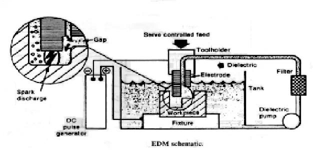
EDM is a non-traditional machining process based on removing material from a part by means of a series of repeated electrical discharges between a tool, called the electrode and the part being machined in the presence of a dielectric fluid. At present EDM is a widespread technique used in industry for high-precision machining of all types of conductive materials such as: metals, metallic alloys, or even some ceramic material of any hardness.
In the electrical discharge machining process, the shape of the electrode determines the shape of the workpiece owing to the electrode being sunk into the workpiece. However, electrode wear takes place during the electrical discharge machining process. This is because each spark discharge removes material not only from the workpiece but also from the electrode. Therefore, the study of electrode wear is important to ensure the required dimensional accuracy and geometry of the workpiece can be achieved.
1.2 Background of the Problem
Electrical discharge machining (EDM) is rapidly becoming an important manufacturing process for machining hard metals and alloy used in the aerospace, tool and dies industries, manufacturing of mould and to produce the complex shape, which required high precision and dimensional accuracy. As been stated, the shape of the electrode will determine the shape of the workpiece or final product. Therefore, the study of electrode wear is important to ensure the required dimensional accuracy and geometry of the workpiece can be achieved.
Hence, this project will analyzed the characteristic and rate of electrode wear under several parameters machining such as current, voltage and jump speed using copper electrode.
1.3 Objectives
The purposes of this project are to:
i. To characterize the mechanism and morphology of tool wear according to current, voltage and jump speed.
ii. To determine the electrode tool wear rate within different machining parameter.
1.4 Scopes
Several approaches are used throughout the project. According to the objectives, the selected scopes of the project are:
i. To understand the EDM die-sinking machining process.
ii. To find the electrode tool wear rate of EDM die-sinking process.
iii. To analyze the type of electrode tool wear under various parameters (current, voltage, jump speed) using Coordinate Measuring Machine (CMM) and Image Analysis Microscope.
iv. To find the significant machining parameter that influences the rate of tool wear using Orthogonal Array approach.
1.5 Important of the Study
The study of electrode wear is important to ensure the required dimensional accuracy and geometry of the workpiece is meet. Beside that, the result from this study will help to estimate the electrode reliability under various machining parameter.
1.6 Expected Result
CHAPTER 2
LITERATURE REVIEW
2.1 Electrical Discharge Machining (EDM)
Figure 2.1: A controlled spark discharge removes a very small particle between workpiece and electrode (circle figure). (George Tlusty, 1999)
Beside that, the Electrical Discharge Machining (EDM) technique is applicable to a wide variety of conductive materials irrespective of their mechanical properties, e.g their hardness, strength or toughness, etc. further more, since no direct contact occurs between electrode and workpiece, the EDM process is suitable for the machining of brittle materials such as ceramic and for those materials which are not really machined using traditional machining method.
2.2 Die-Sinking EDM
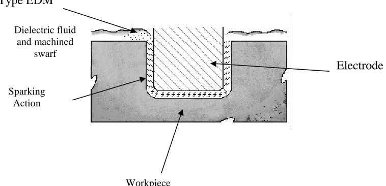
The EDM die-sinking as shown at figure 2.2, has a cutting tool (electrode) shaped to the form of the cavity, mounted in the ram of the machine. The electrically conductive workpiece is fastened to the machine table below electrode. The DC power supply produces a series of short, high frequency electrical arc discharges between the electrode and the workpiece. The action removes (erodes) tiny particles of metal from the workpiece and as the process continues, the electrode reproduces it’s from in workpiece. (Krar, 1996). Figure 2.3 below is also shown the schematic diagram of EDM machining process.
[image:24.612.127.506.342.525.2]Ram Type EDM
Figure 2.2: A cutting tool (electrode) shaped to the form of the cavity (George Tlusty, 1999)
Dielectric fluid and machined
swarf
Sparking Action
Workpiece