This is a repository copy of
Substrate integrated waveguide filters with face-to-face
broadside-coupled complementary split ring resonators
.
White Rose Research Online URL for this paper:
http://eprints.whiterose.ac.uk/82362/
Version: Accepted Version
Proceedings Paper:
Huang, L, Robertson, ID and Yuan, N (2013) Substrate integrated waveguide filters with
face-to-face broadside-coupled complementary split ring resonators. In: European
Microwave Week 2013, EuMW 2013 - Conference Proceedings; EuMC 2013: 43rd
European Microwave Conference. European Microwave Conference, 9-10 October 2013,
Nuremberg, Germany. , 29 - 32. ISBN 9782874870316
[email protected] https://eprints.whiterose.ac.uk/ Reuse
Unless indicated otherwise, fulltext items are protected by copyright with all rights reserved. The copyright exception in section 29 of the Copyright, Designs and Patents Act 1988 allows the making of a single copy solely for the purpose of non-commercial research or private study within the limits of fair dealing. The publisher or other rights-holder may allow further reproduction and re-use of this version - refer to the White Rose Research Online record for this item. Where records identify the publisher as the copyright holder, users can verify any specific terms of use on the publisher’s website.
Takedown
If you consider content in White Rose Research Online to be in breach of UK law, please notify us by
Substrate Integrated Waveguide Filters with
Face-to-Face Broadside-Coupled Complementary Split Ring
Resonators
Liwen Huang
#1, Ian. D. Robertson
#2, Naichang Yuan
* 3#
Dept. of Electronic and Electrical Engineering, University of Leeds Leeds, LS2 9JT, United Kingdom
1
*
Dept. of Electronic and Electrical Engineering, National University of Defense Technology Changsha, 410000, China
2
Abstract—Novel substrate integrated waveguide (SIW) filters using face-to-face oriented broadside-coupled complementary split ring resonators (BC-CSRRs) are presented in this paper. The SIW with the conventional BC-CSRR resonator pairs is first investigated. By removing the metal strip between the two back-to-back rings of the BC-CSRR pair, a modified BC-CSRR pair which shows a significantly improved spurious suppression and a wider rejection bandwidth is then proposed. SIW bandpass filters based on the resonator pairs have been designed, fabricated and measured. The SIW filter with modified BC-CSRR pairs exhibits a great improvement in the stopband performance. The proposed filters work below the cutoff frequency of the main mode of the SIW. They have the usual advantages of the SIW and the BC-CSRR such as compact size, easy fabrication and easy integration with other electronic circuits.
Index Terms—substrate integrated waveguide, microwave filters; microwave integrated circuits; metamaterials
I. INTRODUCTION
In the last few years, there has been a growing interest in the design of microwave filters with the complementary split-ring resonators (CSRRs) [1]-[4] and more recently with various forms of CSRR integrated into a substrate integrated waveguide (SIW) [5]-[10]. This paper investigates an improved form of the broadside-coupled complementary split-ring resonator (BC-CSRR) [6] integrated into the SIW to form a bandpass filter with enhanced stopband performance. The unit cell of the SIW with the conventional BC-CSRR resonator pairs is first investigated. It is shown that, by removing the metal strip between the two back-to-back rings of the BC-CSRR pair, the spurious passband might be inhibited and a very substantial improvement in stop-band rejection could be achieved. Based on this analysis, a novel unit cell of the SIW with a modified BC-CSRR pair is then proposed to further improve the stopband performance. SIW bandpass filters with the resonator pairs are designed and the measured results are compared. It is shown that the SIW filter with the modified BC-CSRR pair shows improved stopband performance in comparison to that with the conventional
BC-CSRR pair. In addition, the proposed filters operate below the cutoff frequency of the SIW. They are compact and they have the usual advantages of SIW technology - namely, low loss, easy fabrication and easy integration with other electrical circuits.
II. SIW WITH FACE-TO-FACE BC-CSRRPAIRS
A. The Face-to-Face Oriented SIW BC-CSRR Resonator Pair
The configuration of the conventional broadside-coupled complementary split-ring resonator (BC-CSRR) is shown in Fig. 1(a), where one of the rings is on the top of the dielectric
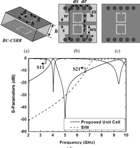
BC-CSRR ds dr s w t l ws ys h d g b (a) (b) (c)
S11 S21
(d)
Fig. 1 (a) Configuration of the BC-CSRR. (b) Top view of the unit cell of the SIW with face-to-face oriented BC-CSRRs. (c) Bottom view of the unit cell. (d) Simulated frequency response of the original SIW and the proposed unit cell (with parameters r = 3.48, h = 0.762 mm, b = 3.9 mm, g = 0.3 mm, d =
[image:2.595.317.542.412.649.2]substrate and the other ring is located on the bottom of the substrate, with the slits placed at 1800 to each other [6]. Based on the structure of the BC-CSRR, a unit cell of SIW combined with face-to-face oriented BC-CSRRs is proposed. As shown in Fig. 1(b)-(c), a pair of BC-CSRRs aligned face to face are employed and etched on the SIW top and bottom metal planes; a microstrip feed line is adopted to excite the SIW cavity and an inset transition is used to better match the microstrip line and the SIW. Since the electric field of the TE10 mode in the SIW is perpendicular to the top and bottom surfaces of the waveguide, it guarantees that the CSRRs can be properly excited [7]. The transmission responses of the proposed SIW BC-CSRR unit cell simulated by the HFSSTM is shown in Fig. 1(d), compared with that of the initial SIW. It can be seen that the resonant frequency is located at 4.03 GHz and it is below the cutoff frequency of the original SIW. However, in the upper stopband, a spurious passband appears at around 9.37 GHz, which eliminates the out-of-band suppression and limits the usefulness of the structure.
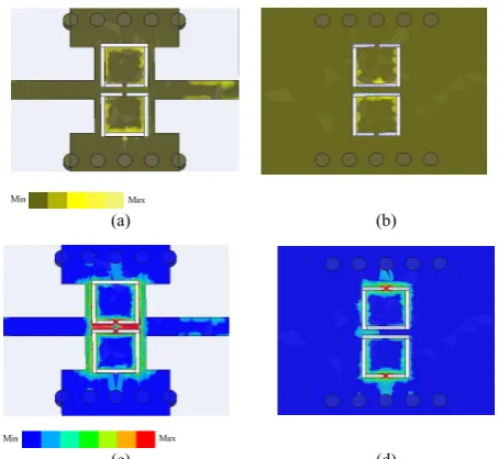
To better understand the spurious passband, the electromagnetic field distribution of the unit cell at 9.37 GHz has been investigated. As shown in Fig.2, both of the electric and magnetic field are mainly distributed on the bottom rings and especially on the middle metal strip line between these two bottom rings. This indicates that the field propagation at 9.37 GHz heavily depends on the middle metal strip line on the bottom. On the contrary, for the fundamental passband at 4.03 GHz as depicted in Fig. 3, the electromagnetic field of the top rings is much stronger than that of the bottom rings and only a little electromagnetic field is distributed on the bottom middle metal strip. This means that the rings on the top play an important role in the field propagation at 4.03 GHz, while the middle metal strip line between the two bottom rings, which is critical for the field propagation of the spurious passband at 9.37 GHz, has only a small effect on the primary passband. Therefore, it is expected that the spurious passband might be suppressed by removing the middle metal strip line between the two bottom rings, with the primary passband only receiving a limited influence.
B. Modified SIW BC-CSRR Resonator Pairs with Improved Spurious Suppression
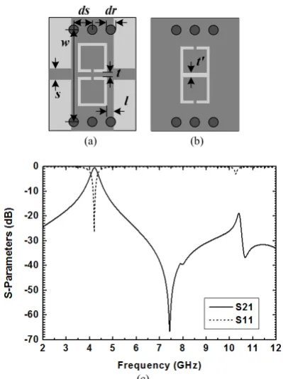
Based on the discussion above, a modified SIW BC-CSRR resonator pair is proposed to improve the spurious suppression by removing the middle metal strip line between the two rings of the BC-CSRR on the bottom broadwall of the SIW. Fig. 4 shows the configuration of the new unit cell, where the middle metal strip line between the two rings on the bottom of the SIW is removed and these two rings are united along the common side. The simulated transmission response of the modified unit cell is shown in Fig. 4(c). Like the frequency response of the original unit cell, a passband is observed, now with the center frequency at 4.2 GHz. As expected, the spurious passband of the original unit cell at 9.37 GHz is suppressed and a broad stopband with an enhanced out-of-band rejection is achieved for the modified unit cell.
(a) (b)
[image:3.595.318.546.57.282.2](c) (d)
Fig. 2 Field distribution of the proposed unit cell at 9.37 GHz: (a) Top view of the electric field distribution; (b) bottom view of the electric field distribution; (c) top view of the magnetic field distribution, and (d) bottom view of the magnetic field distribution.
(a) (b)
(c) (d)
Fig. 3 Field distribution of the proposed unit cell at 4.03 GHz: (a) Top view of the electric field distribution; (b) bottom view of the electric field distribution; (c) top view of the magnetic field distribution, and (d) bottom view of the magnetic field distribution.
[image:3.595.317.544.339.548.2](a) (b)
[image:4.595.303.556.51.249.2](c)
Fig. 4 Configuration of the modified unit cell: (a) top view; (b) bottom view; and (c) simulated transmission responses (with parameters: r = 3.48, h =
0.762 mm, b = 3.9 mm, g = 0.3 mm, d = 0.34 mm, t = 0.5 mm, t’
= 0.34 mm,
w = 12.5 mm, s = 1.68 mm, l = 0.5 mm, dr = 1.2 mm, ds = 2.2 mm).
resonator pair (see Fig. 1) and the modified resonators (see Fig. 4), bandpass filters were designed and optimized with HFSS™. The Rogers RO 4350 substrate with r = 3.48 and a thickness of 0.762 mm was used to fabricate all of the filters. The filters were fabricated using a standard PCB etching process. They were measured by an Agilent E8363A network analyzer.
Fig. 5 shows the layout and photograph of a two-section SIW bandpass filter based on the original unit cell (see Fig. 1). Two completely identical unit cells coupled by an evanescent-mode SIW section are employed. The distance between two resonators can be tuned to obtain the required coupling. Fig. 6(a) shows the simulated and measured transmission response of the filter over the 3 to 6 GHz band. The measured center frequency is 4.15 GHz. The measured 3 dB bandwidth is 0.25 GHz. The insertion loss is approximately 2.8 dB including the feed lines and SMA connectors. Fig. 6(b) shows the measured frequency response over a wide band. It can be seen that the measured stopband rejection is better than 20 dB from 4.46 GHz to 6.88 GHz. Unfortunately, a wide band of unwanted transmission appears between 7.5 GHz to 10 GHz which severely limits the usefulness of the structure.
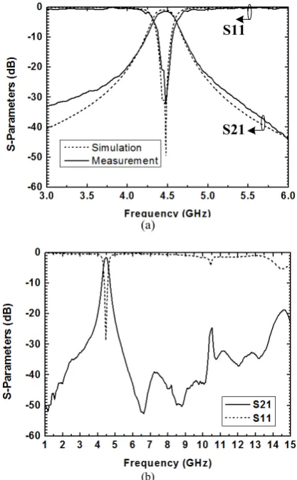
Fig. 7 shows the photograph and the layout of a second-order filter based on the new unit cell (see Fig. 4). Here, the two united back-to-back rings are etched on the top broadwall to better protect the integrity of the ground plane. The simulated and measured transmission responses of the filter over the 3 to 6 GHz band are plotted in Fig. 8(a). The measured center frequency and 3 dB bandwidth are 4.46 and
(a) (b)
(c) (d)
Fig. 5 (a) Photograph of the top of the filter base on the face-to-face aligned SIW BC-CSRR resonator pair. (b)Photograph of the bottom of the filter.(c) Top view of the layout. (d) Bottom view of the layout (with parameters b = 3.9 mm, g = 0.3mm, d = 0.34 mm, t = 0.5 mm, w = 13 mm, s =1.68 mm, ys = 2 mm, ws = 3 mm, l = 0.5 mm, dr = 1.1 mm, ds = 2 mm, ld = 4 mm).
(a)
(b)
[image:4.595.65.265.54.322.2] [image:4.595.323.533.326.666.2](a) (b)
(c) (d)
Fig. 7 (a) Photograph of the top of the filter base on the modified unit cell. (b) Photograph of the bottom of the filter.(c)Top view of the layout. (d) Bottom view of the layout (with parameters h = 0.762 mm, b = 3.9 mm, g = 0.3mm, d
= 0.34 mm, t = 0.34 mm, t’
= 1 mm, w = 12.5 mm, s =1.68 mm, l = 0.5 mm,
dr = 1.1 mm, ds = 2 mm, ld = 4.5 mm).
S11
S21
(a)
[image:5.595.48.284.52.224.2](b)
Fig. 8 (a) Simulated and measured results in the 3 to 6 GHz band. (b) Wideband measurement result.
0.25 GHz, respectively. The measured insertion loss is approximately 1.1 dB including the feed lines and SMA connectors. Fig. 8(b) shows the measured frequency response over a wide band. It can be seen that the measured stopband extends from 5.05 GHz to 15 GHz with better than 20 dB
rejection. By comparing the results shown in Fig. 6(b) and 8(b), it can be seen that the filter with modified BC-CSRR pairs shows enhanced spurious suppression and wider rejection bandwidth.
IV.CONCLUSIONS
This paper presents novel bandpass substrate integrated waveguide (SIW) filters with face-to-face broadside-coupled complementary split ring resonator pairs. The filter employing a conventional BC-CSRR resonator pair is shown to have a very poor spurious-free range. The modified BC-CSRR resonator pair was then proposed to suppress the spurious passband by removing the metal strip between the two lower rings. Bandpass filters with the proposed resonator pairs were designed and fabricated. The filter based on the modified resonator configuration achieved good agreement between the simulation and the measurement. A very significant improvement in stopband suppression was demonstrated. These filters operate below the cutoff frequency of the SIW and are therefore compact in size. They are also easy to fabricate and integrate with other electric circuits, giving great potential for use in low-cost microwave circuits.
REFERENCES
[1] F. Falcone, T. Lopetegi, J. D.Baena, R. Marqués, F. Martín, and M. Sorolla, "Effective negative- stopband microstrip lines based on complementary split ring resonators," IEEE Microw. Wireless Compon. Lett., vol. 14, no. 6, pp. 280-282, Jun. 2004.
[2] J. B. Pendry, A. J. Holden, D. J. Robbins, and W. J. Stewart, "Magnetism from conductors and enhanced nonlinear phenomena,"
IEEE Trans. Microw. Theory Tech. , vol. 47, no. 11, pp. 2075-2084, Nov. 1999.
[3] R. Marque´s, F. Medina, and R. Rafii-El-Idrissi, "Role of bianisotropy in negative permeability and left-handed metamaterials," Phys. Rev. B, , vol. 65, 144440, Apr. 2002.
[4] C. Li, K. Y. Liu, and E. Li, "Design of microstrip highpass filters with complementary split ring resonators," Electron. Lett., vol. 43, pp. 35-36, Jan. 2007.
[5] D. Deslandes, and K. Wu, "Single-substrate integration technique of planar circuits and waveguide filters," IEEE Trans. Microw. Theory Tech., vol. 51, no. 2, pp. 593-596, Feb. 2003.
[6] L. Huang, I. D. Robertson, N. Chang, and J. Huang, "Novel substrate integrated waveguide bandpass filter with broadside-coupled complementary split ring resonators," 2012 IEEE MTT-S Int. Microw. Symp. Dig, 2012.
[7] Y. D. Dong, T. Yang, and T. Itoh, "Substrate integrated waveguide loaded by complementary split-ring resonators and its applications to miniaturized waveguide filters," IEEE Trans. Microw. Theory Tech.,
vol. 57, no. 9, pp. 2211-2223, Sept. 2009.
[8] K. Deng, Z. X. Guo, C. Li, and W. Q. Che, "A compact planar bandpass filter with wide out-of-band rejection implemented by substrate-integrated waveguide and complementary split-ring resonator," Microw. Opt. Technol. Lett., vol. 53, pp. 1483-1487, Jul. 2011.
[9] X. Zhang, Z. Yu, and J. Xu, "Novel band-pass substrate integrated waveguide filter based on complementary split ring resonators," Progr. Electromagn. Res., vol. 72, pp. 39-46, 2007.
[10] Q. L. Zhang, W. Y. Yin, S. He, and L. S. Wu, "Evanescent-mode substrate integrated waveguide (SIW) filters implemented with complementary split ring resonators," Prog. Electromagn. Res., vol. 111, pp. 419-432, 2011.
[image:5.595.62.271.289.627.2]