Int. J. Electrochem. Sci., 9 (2014) 5788 - 5802
International Journal of
ELECTROCHEMICAL
SCIENCE
www.electrochemsci.orgAn Available Method Utilizing the Waste Heat in a Direct
Carbon Fuel Cell
Liwei Chen1, Houcheng Zhang2,*, Songhua Gao1
1
School of Mechanical & Electronic Engineering, Sanming University, Sanming 365004, China;
2
Department of Microelectronic Science and Engineering, Ningbo University, Ningbo 315211, China
*
E-mail: [email protected]
Received: 21 April 2014 / Accepted: 3 July 2014 / Published: 16 July 2014
A new hybrid system is established to utilize the waste heat generated in a DCFC (direct carbon fuel cell). The hybrid system mainly consists of a DCFC with molten carbonate as electrolyte, a regenerator and a Carnot heat engine, where the Carnot heat engine is driven by the high-quality waste heat generated in the DCFC. Based on the electrochemistry and non-equilibrium thermodynamics, expressions for the efficiencies and power outputs of the DCFC, Carnot heat engine and hybrid system are derived, where the different sources of irreversible losses such as the various kinds of overpotentials in the electrochemical reaction process, finite-rate heat transfer between the DCFC and the heat engine, and heat-leak from the DCFC to the environment are considered. It shows that the performance of the DCFC can be greatly enhanced by coupling a Carnot heat engine to further convert the waste heat for power generation. By employing numerical calculations, the effects of some design parameters and operating conditions on the performance of the hybrid system are discussed in detail. The investigation method in the present paper is feasible for some other similar energy conversion systems as well.
Keywords: Direct carbon fuel cell; Heat engine; Hybrid system; Performance optimum analysis
1. INTRODUCTION
choice as high power density for fuel cells can be achieved. However, effective and economic production and storage as well as refueling infrastructure are still facing with big challengers.
Compared with the prevailing hydrogen fuel, carbon is more convenient for storage and transportation and is less fire/explosion hazard. DCFC (direct carbon fuel cell) is a unique electrochemical device which can directly converts the chemical energy of carbon or biomass into electricity without the need for gasification or the moving machinery associated with conventional electric generators [4-6]. Almost all the carbon-rich materials such as coal, natural gas, petroleum, and biomass can be easily converted or purified to the fuel of DCFC. Thus, the DCFC is considered as one of the most attractive solution in the automotive and power generation industry [6-10].
Generally, the working temperature range of DCFC is 973~1073 K [6, 9, 10], and there will be a lot of high-quality waste heat production when the DCFC is put into operation. Thus, it is a task deserving deeply investigation on how to availably utilize the waste heat produced in DCFC. The high-temperature operating characteristics provide the possibility of cogeneration with other types of power generators such as gas turbines or heat engines for further power generation. So far, numerous investigators have carried out on the high-temperature fuel cells such as the solid oxide fuel cells (SOFCs) and molten carbonate fuel cells (MCFCs) based hybrid systems in order to increase the overall performance of the fuel cells [11-15], however, the study on further utilizing the waste heat in DCFCs for power generation through heat engine hybrid system is seldom, the existing method for improving the efficiency for DCFC is always considered a hybrid electrode configuration [16].
In the present paper, we will construct a new typical system to effectively recover the waste heat generated in the DCFC for power generation, the hybrid system mainly composed of a DCFC, a regenerator and a Carnot heat engine. Each component in the hybrid system will be dividedly described, and the numerical expressions for efficiency and power output of the hybrid system are derived by considering not only the irreversible losses in the DCFC but also the heat-leak from the fuel cell to the environment as well as the heat transfer between the fuel cell and the heat engine. Based on numerical calculations, the general performance characteristics are revealed and the optimal regions for some important performance parameters are given, and consequently, the performance characteristics of the hybrid system are optimized.
2. AN IRREVERSIBLE MODEL OF THE DCFC-CARNOT HEAT ENGINE HYBRID SYSTEM
Qloss DCFC (T)
Regenerator
T0
Pcell
Carnot Heat Engine
Qh
Pengine
Ql
[image:2.596.226.349.615.708.2]
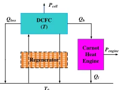
Figure 1 shows the schematic diagram of a DCFC-Carnot heat engine hybrid system, which mainly consists of a DCFC, a Carnot heat engine and a regenerator. The DCFC in the hybrid system plays a role of the high-temperature heat reservoir of the Carnot engine which is employed for a further power generation. The regenerator acts as a counter-flow heat exchanger, which economically absorbs the heat in the high-temperature exhaust gas to preheat the reactants to attain the reaction temperature.
In order to quantitatively analyze the performance of the whole hybrid system, the following major assumptions are often adopted [15, 17-20]:
(1) Both the DCFC and the Carnot engine are operated under steady-state condition; (2) The regenerator is regarded as a perfect one;
(3) Operating temperature and pressure are uniform and constant in the DCFC; (4) All gases involved are assumed to be compressible ideal gases;
(5) The carbon fuel is regarded as a rigid sphere and packed with a simple hexagonal pattern;
(6) The concentration overpotential in the anode is assumed to be negligible.
In the following, we will individually analyze each component in the hybrid system and then globally study the performance of the whole hybrid system.
2.1. The DCFC
Figure 2. The schematic diagram of a packed bed anode DCFC with molten carbonate electrolyte.
[image:3.596.184.413.399.634.2]
electrolyte sandwiched in between the two electrodes, where the anode, electrolyte, and cathode are made of graphite, Li2CO3/K2CO3 eutectic melt with a molar ratio of 32:68, and lithium doped NiO,
respectively [7, 20]. DCFC converts the chemical energy in a carbon fuel directly into electricity without the need for gasification. Fine (submicron) carbon particles in an electrochemical cell are electrochemically oxidized at high temperature with the overall fuel cell reaction being:
2 2 CO O
C . The reactions in DCFC produce almost pure CO [21-25], the provided high purity 2 graphite can be contained in a concentrated stream and easily captured for downstream use or disposal avoiding the need for costly gas separation technologies. The basic thermodynamic relationship for the overall reaction in the DCFC can be given as [7, 8, 20]
e h
H I
n F
, (1)
where ne is the number of mole electrons transferred per mole graphite ( ne 4), F is Faraday’s constant, I is the operating electric current of the DCFC [19], and (h) is the molar enthalpy change which can be calculated from the data provide in Ref. [20]. According to the basic thermodynamic relationship: H G T S, the total energy (H) can be divided into two parts, i.e., (G) and ( T S), which are representative of electrical energy and thermal energy, respectively. As long as the enthalpy change is more negative than the Gibbs free energy change of the reaction, the part of the total energy,( T S),cannot be converted to electrical energy, which will be released as heat [14, 15].
Based on the model established by Zhang et al. [20], the power output and efficiency of the DCFC can be, respectively, expressed as
,an ,cat
cell act act ohm con
P JA E V V V V ,
(2) and cell P H
,an ,cat
e
act act ohm con
n F
E V V V V
h
, (3)
where
2 2 2 2 0O , cat CO , cat
e CO , an
( )
ln
e
p p
g T RT E
n F n F p
, (4)
2
,an ln 1
2 2 exp / 2 exp /
act
B B B B
RT J J
V
F K E T K E T
, (5)
1 2 1 2
2 2 2 2
2
,cat 0 0
0, CO ,cat O ,cat 0, CO ,cat O ,cat
ln 1
2 2 ( ) ( ) 2 ( ) ( )
act r r r r
cat cat
RT J J
V
F J p p J p p
2
0 1.5
1 1 ,0
( ) 3
1
exp / 4
s s
N N
s g r
c e c
ohm e
i s a i c
N i F F
D N D
V J JN
E RT LW cM LW
2 0.67 O ,catexp( / ) R exp( / )
A
J B T C D f T
p
, (7)
lim lim ln con e J RT V
n F J J
, (8)
[image:5.596.89.468.72.189.2]J is the operating current density; the subscripts “an” and “cat” indicate, respectively, “anode” and “cathode”; the pk are the partial pressures of species k at the anode or cathode; g0(T) is the Gibbs free energy change at the standard pressure (1 atm) which can be calculated from the data in Ref. [20] ; Ns is the number of the slabs, which depends on the bed height H and the diameter of the carbon particle Dc, i.e., Ns H/Dc; Fg is the vertical gravitational force of an graphite particle; Fr is the repulsive force between two neighboring particles; is the voidage of the packed bed; c,0 is the conductivity of the graphite particle; M is the stress at the elastic limit, c is related to the shape and size of the surface irregularities; JlimneFKCO2CCOb 2 is the limiting current density, KCO2 is the mass transportation coefficient of CO2, and CCOb 2 is the concentration of CO2 in the bulk; and the values of parameters used in the modeling of DCFC are listed in Table 1 [7, 20, 26].
Table 1. Parameters used in the modeling of a DCFC [7, 20, 26].
Parameter Value
Charge transfer coefficient, β 0.5
Operating pressure, P (Pa) 1.01325×10⁵
Ideal gas constant, R (J/mol K) 8.314
Faraday constant, F (C/mol) 96,485
Height of packed bed anode, H (m) 1.0×10⁻³
Length of packed bed anode, L (m) 1.0×10⁻²
Width of packed bed anode, W (m) 1.0×10⁻²
Diameter of spherical graphite particle, Dc (m) 1.0×10⁻⁵ Concentration independent cathode exchange current
density, j00,cat (A/m2)
5.0×10²
Conductivity of electrode phase, σc,0 (s/m2
) 1.6×10⁵
Density of graphite particle, ρc (kg/m3) 1.5×10³
Density of electrolyte, ρe (kg/m3) 2.0×10³
Acceleration of gravity, g (m/s2) 9.8
Pre-exponential factor of the backward reaction, KB (A/m2)
5.8×10⁹
Apparent activation energy in Eq. (7), Ea (J/mol) 2.191×10⁴ Mass transport coefficient of CO2, KCO2(m/s) 3.5×10
-2
Constant in Eq. (6), r1 -1.250
Constant in Eq. (6) , r2 0.375
Bulk gas compositions at the cathode side 67%CO2/33% O2
Operating temperature of DCFC, T (K) 923
Temperature of environment, T0 (K) 298
2.2. The Carnot heat engine
Carnot
P
engineU
1U
2Q
HQ
LT
1T
2T
0T
A
1 [image:6.596.164.444.248.503.2]A
2Figure 3. The schematic diagram of an endoreversible Carnot heat engine.
For the sake of convenience, an endoreversible Carnot cycle model [27], as shown in Figure 3, is adopted to study the effects of the irreversibilities of heat conduction on the performance of the heat engine in the hybrid system, where the heat QH is the heat flux transferred from the high temperature heat reservoir, i.e., DCFC, at T to the working fluid at T1 , and QL from the working fluid at T2 to the environment at T0. In the model, it is assumed that the working fluid flows stably during the whole cycle period of the heat engine, that heat transfer between the reservoirs and the working fluid obeys Newton’s law, and that the influence of other irreversible effects is negligible except the irreversibilities of heat conduction [27-29]. Thus, we obtain
1 1( 1) H
2 2( 2 0) L
Q U A T T , (10) and
1 2
H L
Q Q
T T , (11)
where U1 and U2 are, respectively, the heat conductivities between the working fluid and the heat reservoirs, A1 and A2 denote the heat transfer areas between the working fluid and the heat reservoirs.
As illustrated in Figure 3, a part of the waste heat produced in the DCFC is directly released as heat-leak to the environment, and this amount of the heat flow can be given by [18, 27, 29]
0
( )
loss l
Q KA TT , (12)
where K is the convective heat-leak coefficient, and Al denotes the effective heat-transfer area. Combined with the previous analysis, the rate of waste heat from the DCFC to the heat engine is given by
cell
H loss
Q H P Q
0
( )
cell l
e JA
h P KA T T n F
. (13)
Based on Eqs. (9)-(13), it can be easily proved that when A1/A2 U2 /U1 , the optimum efficiency and power output of the heat engine at given QH and Ah may be expressed as
0 1
1 / /
engine T T QH a
0 2 3 0
1 1
/ 1 cell ( / 1)
T T a J a T T
, (14)
and
engine H engine
P Q
1 2 0 cell 1 3( 0) engine
a a JT a T T
, (15)
where
2 1 h 1 2/ 1 2 a A U U U U , 2
0 1 e A h a
T a n F
, 3
1 l KA a
a
, and Ah A1A2 is the overall heat transfer area of the heat engine.
2.3. The regenerator
the whole hybrid system can be ensured to work normally and continually under the condition of steady-state.
2.4. The efficiency and power output of the hybrid system
Based on equations (2), (3), (14) and (15), one may obtain the efficiency and the power output of the entire DCFC-Carnot heat engine hybrid system, i.e.,
3
2 0
1 ( 1)
hybrid cell cell engine
a T
Ja T
, (16)
and
30 1 2
2 0
1 ( 1)
hybrid cell cell engine
a T
P JT a a
Ja T
. (17)
It is seen from equations (16) and (17) that the efficiency and the power output of hybrid system are larger than that of a sole DCFC, and the efficiency and power output are closely dependent on the irreversible losses including the irreversibilities within the fuel cell itself and originating from the heat transfer between the DCFC and the Carnot heat engine. In the next section, the general performance characteristics and the optimal criteria of the hybrid system will be revealed.
3. GENERAL PERFORMANCE CHARACTERISTICS AND OPTIMAL CRITERIA
Optimal design and analysis of the hybrid system require a thorough understanding of its performance limitations. Equations (16) and (17) clearly show that the performance of the hybrid system depends on a set of thermodynamic and electrochemical parameters such as fuel cell temperature (T ), operating current density (J), DCFC design parameter (Ns), and the parameters related to the heat transfer between the DCFC and the Carnot heat engine as well as the heat-leak to the surroundings, i.e., a1, a2 and a3. In the following calculations, the parameters a11.0 W K 1,
2 1
2 0.00185m A
a , a3 0.001 are chosen. The related values of the input parameters not
mentioned are summarized in Table 1, and these parameters are kept constants unless mentioned specifically.
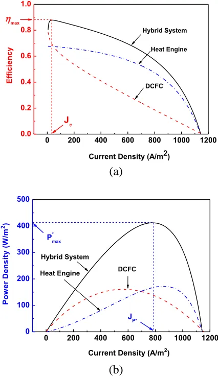
By using Eqs. (16) and (17), the efficiency and power density of the hybrid system varying with the operating current density are presented in Figure 4, where P* P/A is the power density. It can be clearly seen from Figure 4 that both the efficiency and power density of the hybrid system first increase and then decrease as the current density increases, and there exist a maximum efficiency max and a maximum power density Pmax* , where J and JP* are, respectively, the corresponding current
densities at the maximum efficiency max and maximum power density * max
significantly improved because the waste heat in the fuel cell is further utilized through a Carnot heat engine. Both the efficiency and the power density augment with the increase of current density in the region of J J, while both of them reduce with the increasing current density in the region of
*
P
J J . It is obvious that the regions of J J and J JP* are not optimal from the thermodynamic
viewpoint although the hybrid system may work in these regions. Hence, the optimal region of the current density should be located in
*
P
J J J . (18)
It shows that J and JP* determine the lower and upper bounds of the optimum current
density, respectively. In the practical operation of the DCFC-Carnot heat engine hybrid system, engineers should choose a reasonable current density according to Eq. (18) to ensure that the system is operated in the optimal region.
0 200 400 600 800 1000 1200
0.0 0.2 0.4 0.6 0.8 1.0
DCFC Heat Engine Hybrid System
J
max
Current Density (A/m2)
E
ff
ic
ie
n
c
y
(a)
0 200 400 600 800 1000 1200
0 100 200 300 400 500
DCFC
Heat Engine Hybrid System
JP* P*
max
Current Density (A/m2)
P
o
w
e
r
D
e
n
s
it
y
(
W
/m
2)
[image:9.596.185.398.282.650.2](b)
Figure 4. The curves of (a) the efficiency, and (b) the power density varying with the current density, where Phybrid* Phybrid /A is the power density, J and JP* are the current densities at maximum efficiency max and maximum power density
* max
Figure 5 shows the power density versus the efficiency at different operating temperatures, where Pm* and m are, respectively, the power density at the maximum efficiency max and the efficiency at the maximum power output *
max
P . According to Figure 5, one can determine the optimally operating region, which has a negative slope in the part of the ~P* curve. When the hybrid system operates in this region, the power density will decrease as the efficiency increase, and vice versa. Thus, the optimal ranges of the efficiency and power density are given as
max m
, (19) and
* * *
m max
P P P , (20) respectively.
0.0 0.2 0.4 0.6 0.8 1.0
0 100 200 300 400 500 600
m
P*
m
max
P*
max
Efficiency
P
o
w
e
r
D
e
n
s
it
y
(
W
/m
2)
T =923K
T =973K
T =1023K
T =1073K
Figure 5. The curves of the power density varying with the efficiency at different operating temperatures.
The above results show that Pm*, m , Pmax* and max are four important parameters of the DCFC-Carnot heat engine hybrid system, where *
m
P and m determine the allowable optimum values of the lower bounds of the power density and efficiency, while Pmax* and max determine allowable optimum values of the upper bounds. It should note that the four important parameters closely depend on the thermodynamic and electrochemical parameters of the hybrid system and can be calculated numerically for the given values of other parameters.
4. RESULTS AND DISCUSSION
[image:10.596.55.536.105.458.2]
systems in order to increase the overall efficiencies of fuel cells [32-35]. However, the research activities about high temperature fuel cell based hybrid systems always focus on solid oxide fuel cells (SOFCs) and molten carbonate fuel cells (MCFCs), but the DCFC-heat engine hybrid system has never been studied. The established system model in this paper can be used to investigate the effects of various operating conditions and designing parameters on the performance of the DCFC hybrid system. In this section, a parametric analysis is carried out based on the performance criteria for the variation of operating parameters to characterize the system behavior. Next, the influences of different operating conditions on the performance of the system will be discussed respectively.
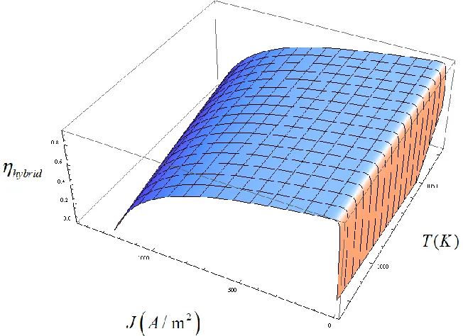
Figure 6. The three-dimensional curve of the efficiency varying with the current density and temperature, where the related values of parameters are listed in Table 1.
The operating temperature of the system is an important parameter because it directly affects the various overpotentials of the fuel cell as well as the performance of the heat engine. The power density and efficiency of the DCFC-Carnot heat engine hybrid system operating at a temperature range
of 973 ~ 1073 K and a current density range of 0 ~ 1450 A m-2 are presented in Figure 6 and Figure 7.
[image:11.596.136.462.224.461.2]
the whole system that can be operated at that specified temperature. A similar result has appeared in other papers for high-temperature fuel cell hybrid system [11-15], thus it may be seen as a same result for this kind of systems.
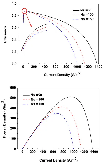
For DCFC-Carnot heat engine hybrid system, the structure of DCFC also has great influence on the performance of the system. We will take the anode dimension as an example to discuss the effect of internal structure. As shown in Figure 8, the curves of the efficiency and the power density varying with the current density at different Ns, i.e., different anode dimension, are given. From Figure 8, it is evident that the influence of anode dimension on the maximum power density is larger than that on the maximum efficiency. In addition, the greater the anode dimension, the smaller efficiency and power density will be. It is distinct that the ohmic overpotential of DCFC will increase as the growth of the number of slabs, and accordingly, the performances of DCFC and the hybrid system will be deteriorated.
Figure 7. The three-dimensional curve of the power density varying with the current density and temperature, where the values of the relevant parameters are the same as those used in Figure 6.
[image:12.596.65.530.282.564.2]
heat transfer irreversibility in the heat engine is and the better the performance of the hybrid system can be expected.
0 200 400 600 800 1000 1200 1400 0.0
0.2 0.4 0.6 0.8 1.0
Current Density (A/m2)
E
ff
ic
ie
n
c
y
Ns =50
Ns =100
Ns =150
0 200 400 600 800 1000 1200 1400 0
100 200 300 400 500 600
Current Density (A/m2)
P
o
w
e
r
D
e
n
s
it
y
(
W
/m
2 )
Ns =50
Ns =100
[image:13.596.107.460.119.677.2]Ns =150
0 200 400 600 800 1000
0.0 0.2 0.4 0.6 0.8 1.0
a2
opt
10-6
P
o
w
e
r
D
e
n
s
it
y
(
W
/m
2
)
E
ff
ic
ie
n
c
y
J =500A/m2
a2
J =1000A/m2
0 100 200 300 400 500 600
Figure 9. The curves of the efficiency and power density of the hybrid system varying with the parameter a2.
The parameter a2 is a colligation measurement for the systemic structure. It may be proved that there is a common extreme condition of hybrid / a2 Phybrid / a2 0 for the hybrid system. It implies the fact that there is a common optimum value of
2opt
a at which both the power output and efficiency will attain their maxima simultaneously, as shown in Figure 9.
From Eqs. (16) and (17), it can be also proved that the power density and efficiency of the hybrid system are monotonically decreasing functions of a3. Its physical meaning can be easily explained as follows: a3 is a synthesized parameter to measure the heat-leak irreversibility from the fuel cell to the surroundings. The smaller the parameter a3 is, the better the performance of the hybrid system will be.
5. CONCLUSIONS
The importance of present paper lies in a new hybrid system is established to use the waste heat generated in the high-temperature DCFC. It is found that the performance of the DCFC can be greatly enhanced by using a Carnot heat engine for further power generation. Moreover, the effects of some important parameters such as temperatures, operating current density, the internal configuration of DCFC, and a variety of irreversible losses on the performance of the DCFC are illustrated. The optimum criteria of some important performance parameters such as the power density and efficiency of the hybrid system are given. The results obtained here may provide some theoretical basis for the performance enhancement of practical DCFCs.
ACKNOWLEDGEMENTS
[image:14.596.191.417.84.234.2]
Province (No. 2012J01016), Key Project in the Educational Office of Fujian Province (No. JA13291), Natural Science Foundation of Ningbo City (No. 2013A610139), and Foundation of Zhejiang Educational Commission (No. Y201326937).
References
1. A Di Carlo, E Bocci, V Naso, Int J Hydrogen Energy, 38 (2013) 532. 2. M Santin, A Traverso, L Magistri, A Massardo, Energy, 35 (2013) 1077. 3. H Park, Energy Convers Manage, 81 (2014) 220.
4. C Li, Y Shi, N Cai, J Power Sources, 195 (2010) 4660. 5. D Cao, Y Sun, G Wang, J Power Sources, 167 (2007)250.
6. N Cherepy, R Krueger, K Fiet, A Jankowski, J Cooper, J Electrochem Soc, 152 (2005) 80. 7. Q Liu, Y Tian, C Xia, L Thompson, B Liang, Y Li, J Power Sources, 185 (2008) 1022. 8. J Bockris, J Kim, J Appl Electrochem, 27 (1997) 890.
9. K Hemmes, M Houwing, N Woudstra, J Fuel Cell Sci Technol, 7 (2010) 051008. 10.A Elleuch, A Boussetta, K Halouani, J Electroanalyt Chem, 668 (2012) 99. 11.Y Zhao, J Chen, J. Power Sources 186 (2009) 96.
12.H Zhang, G Lin, J Chen, Int J Electrochem Sci, 6 (2011) 4714. 13.H Zhang, S Su, G Lin, J Chen, Int J Electrochem Sci, 7 (2012) 3420. 14.L Chen, H Zhang, S Gao, H Yan, Energy, 64 (2014) 923.
15.L Chen, S Gao, H Zhang, Int. J. Electrochem. Sci., 8 (2013)10772.
16.J Ruflin, A Perwich, C Brett, J Berner, S Lux, J Power Sources, 213 (2012) 275. 17.H Kim, J Bae, D Choi, Int. J. Hydrogen Energy, 38 (2013) 4782.
18.C Li, Y Shi, N Cai, J Power Sources, 196 (2011)754.
19.Y Zhao, C Ou, J Chen, Int. J. hydrogen energy, 33 (2008) 4161. 20.H Zhang, L Chen, J Zhang, J Chen, Energy 68 (2014) 292.
21.J Cooper. Direct conversion of coal and coal-derived carbon in fuel cells. ASME paper No. KH-3, 2004.
22.K Hemmes, M Houwing, N Woudstra, 7 (2010) 051008.
23.D Vutetakis, DR Skidmore, HJ Byker, J Electrochem Soc 134 (1987) 3027. 24.Y Xie, Y Tang, J Liu, J Solid State Electrochem, 17 (2013)121.
25.X Li, H Zhu, R De Marco, A Dicks, Bradley J, Liu S, Lu GQ, Ind Eng Chem Res, 47 (2008) 9670. 26.G Wilemski, J Electrochem Soc 130 (1983) 117.
27.J Chen, J. Appl. Phys., 72 (1992) 3778. 28.J Chen, Z Yan, J. Appl. Phys, 63 (1988) 4795.
29.A Durmayaz, O Sogutb, B Sahinc, H Yavuz, Prog. Energy Combust. Sci., 30 (2004) 175. 30.MR Quddus, Y Zhang, AK Ray, Chem. Eng., 165 (2010) 639.
31.N Autissier, F Palazzi, F Marechal, J van Herle, D Favrat, J. Fuel Cell Sci. Technol., 4 (2007) 123. 32.J W Burbank, D Witmer, F Holcomb, J Power Sources, 193 (2009) 65.
33.C Haynes, J Power Sources, 92 (2001) 199.
34.D Sa´nchez, R Chacartegui, M Torres, T Sa´nchez, J Power Sources, 192 (2009) 84. 35.J Qin, W Zhou, W Bao, D Yu, Int J Hydrogen Energy, 35 (2010) 356.

![Table 1. Parameters used in the modeling of a DCFC [7, 20, 26].](https://thumb-us.123doks.com/thumbv2/123dok_us/1900726.148124/5.596.89.468.72.189/table-parameters-used-modeling-dcfc.webp)